Opel Insignia: Repair Instructions
Rear Wheel Bearing and Hub Replacement (AWD)
Removal Procedure
1. Remove the rear tire and wheel assembly.
2. Rear Wheel Speed Sensor - Remove.
3. Rear Wheel Drive Shaft@Rear Wheel Bearing and Hub Assembly - Separate.
- Rear Wheel Drive Shaft Replacement - Left Side
- Rear Wheel Drive Shaft Replacement - Right Side
4.
.png)
Rear Brake Rotor(1) - Remove.
5.
.png)
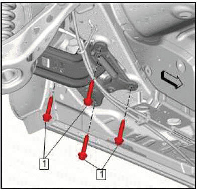
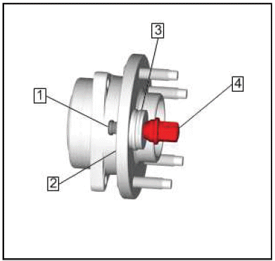
Rear Wheel Hub Bolt(1) - Remove[3x].
6.
.png)
Rear Wheel Bearing and Hub Assembly(1) - Remove.
Installation Procedure
NOTE: Avoid applying grease to any other machined surface, holes, or threads.
Ensure the drain channel at the bottom of the bore is not blocked with grease or debris.
1. Apply grease evenly and ensure complete coverage to the knuckle bearing pilot bore only.
2. Prepare the rear wheel hub bolts for installation as follows:
- Remove all traces of the adhesive patches from the rear wheel hub bolts.
- Clean the threads of the rear wheel hub bolts with denatured alcohol.
- Apply thread locking adhesive to the rear wheel hub bolts.
- Ensure there are no gaps in the thread locking adhesive along the length of the filled area of the threads on the bolt shafts.
3.
.png)
Rear Wheel Bearing and Hub Assembly(1) - Install.
4.
.png)
CAUTION: Refer to Fastener Caution.
5. Rear Wheel Hub Bolt(1) - Install and tighten[3x]
- First Pass: 100 N.m (74 lb ft)
- Final Pass: (15-30 degrees)
6.
.png)
Rear Brake Rotor(1) - Install.
7. Rear Wheel Drive Shaft@Rear Wheel Bearing and Hub Assembly - Install.
- Rear Wheel Drive Shaft Replacement - Left Side
- Rear Wheel Drive Shaft Replacement - Right Side
8. Rear Wheel Speed Sensor - Install.
9. Install the rear tire and wheel assembly.
10. Remove the support and lower the vehicle.
REAR WHEEL BEARING AND HUB REPLACEMENT (FWD)
Removal Procedure
1. Raise and support the vehicle.
2. Remove the rear tire and wheel assembly.
3. Rear Wheel Speed Sensor - Remove.
4.
.png)
Rear Brake Rotor(1) - Remove.
5.
.png)
Rear Wheel Hub Bolt(1) - Remove[3x].
6.
.png)
Rear Wheel Bearing and Hub Assembly(1) - Remove.
Installation Procedure
NOTE: Avoid applying grease to any other machined surface, holes, or threads.
Ensure the drain channel at the bottom of the bore is not blocked with grease or debris.
1. Apply grease evenly and ensure complete coverage to the knuckle bearing pilot bore only.
2. Prepare the rear wheel hub bolts for installation as follows:
- Remove all traces of the adhesive patches from the rear wheel hub bolts.
- Clean the threads of the rear wheel hub bolts with denatured alcohol.
- Apply thread locking adhesive to the rear wheel hub bolts.
- Ensure there are no gaps in the thread locking adhesive along the length of the filled are of the threads on the bolt shafts.
3.
.png)
Rear Wheel Bearing and Hub Assembly(1) - Install.
4.
.png)
CAUTION: Refer to Fastener Caution.
Rear Wheel Hub Bolt(1) - Install and tighten[3x].
- First Pass: 100 N.m (74 lb ft)
- Final Pass: (15 - 30 degrees)
5.
.png)
Rear Brake Rotor(1) - Install.
6. Rear Wheel Speed Sensor - Install.
7. Install the tire and wheel assembly.
8. Remove the support and lower the vehicle.
Knuckle Replacement (FWD)
Removal Procedure
1. Remove the rear tire and wheel assembly.
2. Rear Brake Caliper Bracket - Remove.
3. Rear Brake Rotor - Remove.
4. Rear Brake Shield - Remove.
5. Rear Wheel Bearing and Hub Assembly - Remove.
6.
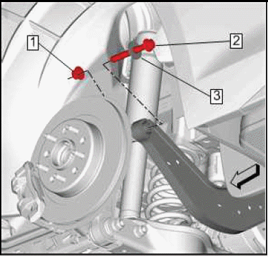
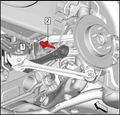
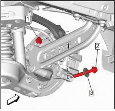
.png)
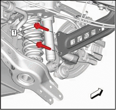
Rear Suspension Upper Control Arm Outer Nut(1) - Remove.
7. Rear Suspension Upper Control Arm Outer Bolt(2) - Remove.
8.
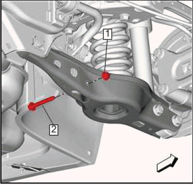
.png)
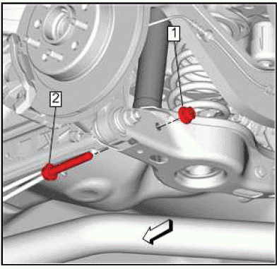
Rear Suspension Adjust Link Nut(1) - Remove.
9. Rear Suspension Adjust Link Outer Bolt(1) - Remove.
10. Support the lower control arm.
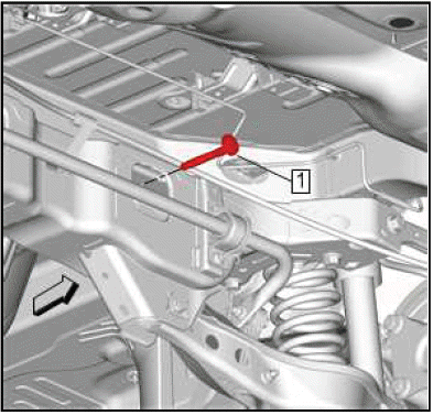
11.
.png)
Rear Suspension Lower Control Arm Outer Nut(1) - Remove.
12. Rear Suspension Lower Control Arm Outer Bolt(2) - Remove.
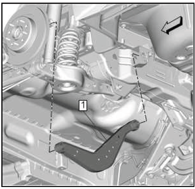
13.
.png)
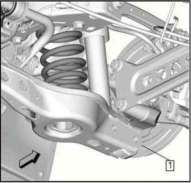
Lower the rear suspension lower control arm (1) to provide clearance for the rear suspension trailing arm bolt.
14. Rear Suspension Trailing Arm Bolt(2) - Remove[2x] - Trailing Arm Replacement.
15.
.png)
Rear Knuckle(1) - Remove.
Installation Procedure
1.
.png)
Rear Knuckle(1) - Install.
2.
.png)
Rear Suspension Trailing Arm Bolt(2) - Install[2x].
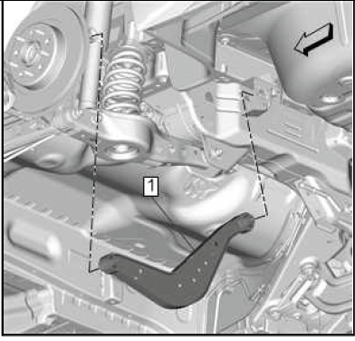
3.
.png)
Raise the rear suspension lower control arm (1) back into position. 4.
.png)
Rear Suspension Lower Control Arm Outer Bolt(2) - Install.
5. Rear Suspension Lower Control Arm Outer Nut(1) - Install.
6. Remove the support from the rear suspension lower control arm.
7.
.png)
Rear Suspension Adjust Link Outer Bolt(2) - Install.
8. Rear Suspension Adjust Link Nut(1) - Install.
9.
.png)
Rear Suspension Upper Control Arm Outer Bolt(2) - Install.
10. Rear Suspension Upper Control Arm Outer Nut(1) - Install.
11. Rear Wheel Bearing and Hub Assembly - Install.
12. Rear Brake Shield - Install.
13. Rear Brake Rotor - Install.
14. Rear Brake Caliper Bracket - Install.
15. Install the rear tire and wheel assembly.
KNUCKLE REPLACEMENT (AWD)
Removal Procedure
1. Raise and support the vehicle.
2. Remove the rear tire and wheel assembly.
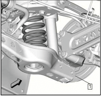
3.
.png)
Rear Brake Rotor (1) - Remove.
4. Rear Wheel Speed Sensor@Rear Suspension Knuckle - Remove.
5.
.png)
Rear Wheel Bearing and Hub Assembly(1) - Remove.
6.
.png)
Rear Brake Shield(1) - Remove.
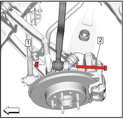
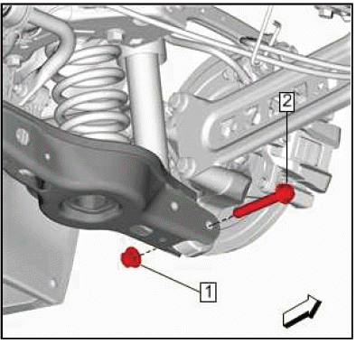
7.
.png)
Rear Stabilizer Shaft Link(1)@Rear Suspension Knuckle - Separate.
8.
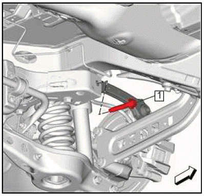
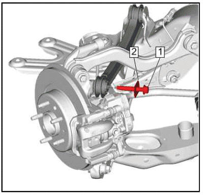
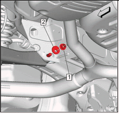
.png)
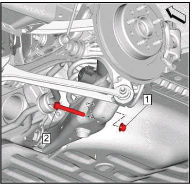
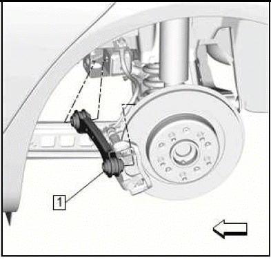
Rear Suspension Adjust Link(1) @Rear Suspension Knuckle - Separate.
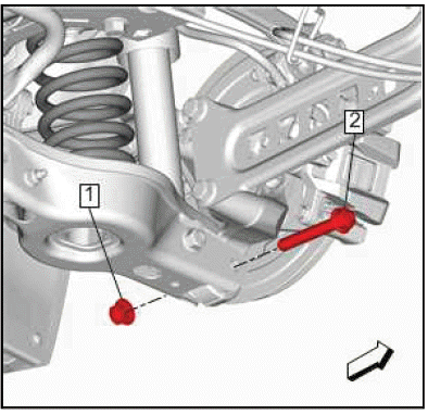
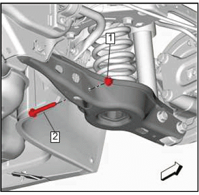
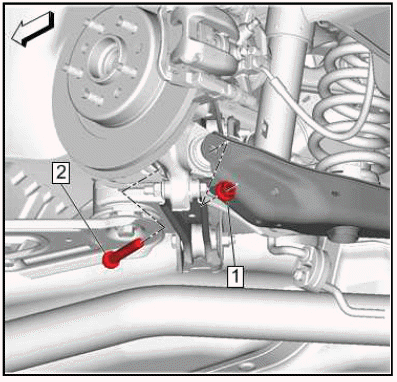
9.
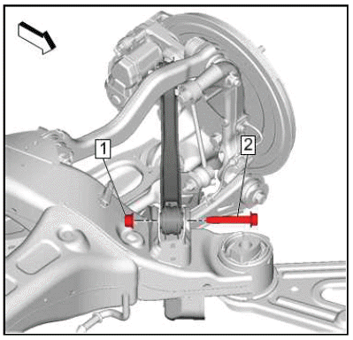
.png)
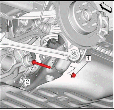
Rear Suspension Lower Trailing Link(1)@Rear Suspension Knuckle - Separate.
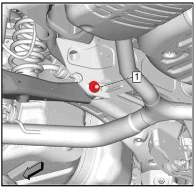
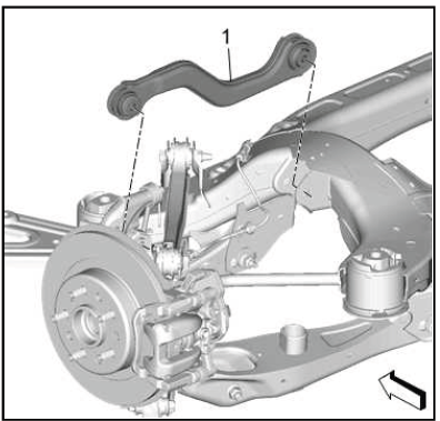
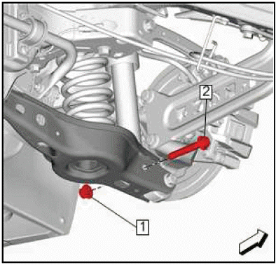
10.
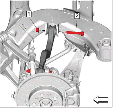
.png)
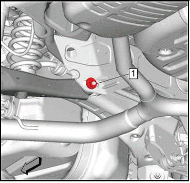
Rear Suspension Upper Trailing Link(1)@Rear Suspension Knuckle - Separate.
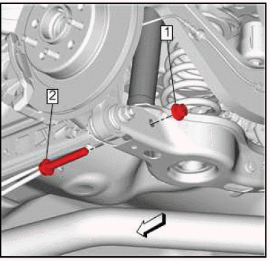
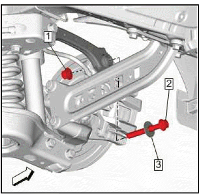
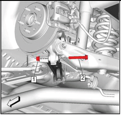
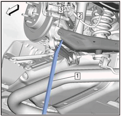
11.
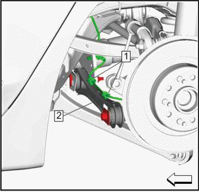
.png)
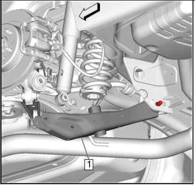
Rear Suspension Lower Control Arm(1)@Rear Suspension Knuckle - Separate.
12.
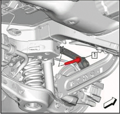
.png)
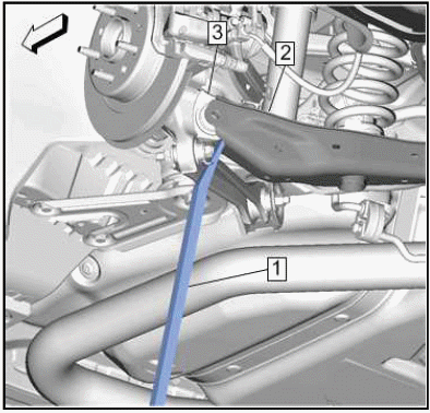
Rear Suspension Upper Lateral Link(1)@Rear Suspension Knuckle - Separate.
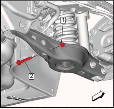
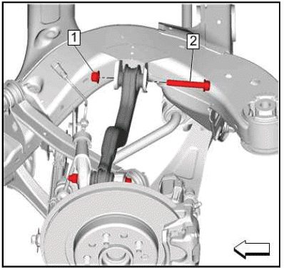
13.
.png)
Rear Suspension Knuckle(1) - Remove.
Installation Procedure
1.
.png)
NOTE: Prior to assembly it is recommended to reposition the rear suspension knuckle bushing to aid during installation.
Install a suitable socket (2) that is slightly smaller than the outside diameter of the rear suspension knuckle bushing (1).
2. Install a suitable socket (3) that is larger than the outside diameter of the rear suspension knuckle bushing on the opposite side of the rear suspension knuckle (6).
3. Install a suitable bolt (4) and nut (5).
4.
.png)
Ensure that the socket (1) is larger than the rear suspension knuckle bushing and sits flush against the rear suspension knuckle (2).
5.
.png)
Rotate the nut (1) forcing the socket (2) and the rear suspension knuckle bushing (3) flush with the rear suspension knuckle (4).
6.
.png)
Rear Suspension Knuckle(1) - Install.
7.
.png)
Rear Suspension Upper Lateral Link(1)@Rear Suspension Knuckle - Install.
8.
.png)
Rear Suspension Lower Control Arm(1)@Rear Suspension Knuckle - Install.
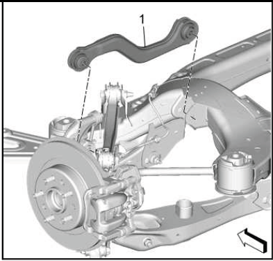
9.
.png)
Rear Suspension Upper Trailing Link(1)@Rear Suspension Knuckle - Install.
10.
.png)
Rear Suspension Lower Trailing Link(1)@Rear Suspension Knuckle - Install.
11.
.png)
Rear Suspension Adjust Link(1) @Rear Suspension Knuckle - Install.
12.
.png)
Rear Stabilizer Shaft Link(1)@Rear Suspension Knuckle - Install.
13.
.png)
Rear Brake Shield(1) - Install.
14.
.png)
Rear Wheel Bearing and Hub Assembly(1) - Install.
15. Rear Wheel Speed Sensor@Rear Suspension Knuckle - Install.
16.
.png)
Rear Brake Rotor(1) - Install.
17. Install the rear tire and wheel assembly.
18. Remove the support and lower the vehicle.
Stabilizer Shaft Replacement (FWD)
Removal Procedure
1. Raise and support the vehicle.
2.
.png)
Rear Stabilizer Shaft Link Nut(1)@Right Side - Remove.
3. Rear Stabilizer Shaft Link Bolt(2)@Right Side - Remove and DISCARD.
4.
.png)
Rear Stabilizer Shaft Link Nut(1)@Left Side - Remove.
5. Rear Stabilizer Shaft Link Bolt(2)@Left Side - Remove and DISCARD.
6.
.png)
Rear Stabilizer Shaft Insulator Clamp Bolt(1) - Remove[4x].
7.
.png)
Rear Stabilizer Shaft(1) - Remove.
Installation Procedure
1.
.png)
Rear Stabilizer Shaft(1) - Install.
2.
.png)
CAUTION: Refer to Fastener Caution.
Rear Stabilizer Shaft Insulator Clamp Bolt(1) - Install and tighten[4x] 58 N.m (43 lb ft).
3.
.png)
CAUTION: This vehicle is equipped with torque-to-yield or single use fasteners. Install a NEW torque-to-yield or single use fastener when installing this component.
Failure to replace the torque-to-yield or single use fastener could cause damage to the vehicle or component.
NOTE: Ensure that there are no gaps in the threadlocker along the length of the filled area of the threads on the shaft. Allow the threadlocker to cure approximately 10 minutes before installation of the nut.
Apply GM specified threadlocker or industry equivalent to the rear stabilizer shaft link bolt threads.
4. Rear Stabilizer Shaft Link Bolt(2)@Left Side - Install a NEW bolt.
5. Rear Stabilizer Shaft Link Nut(1)@Left Side - Install.
Tighten the Bolt
- First Pass: 58 N.m (43 lb ft)
- Final Pass: (45-60 degrees)
6.
.png)
NOTE: Ensure that there are no gaps in the threadlocker along the length of the filled area of the threads on the shaft. Allow the threadlocker to cure approximately 10 minutes before installation of the nut.
Apply GM specified threadlocker or industry equivalent to the rear stabilizer shaft link bolt threads.
7. Rear Stabilizer Shaft Link Bolt(2)@Right Side - Install a NEW bolt.
8. Rear Stabilizer Shaft Link Nut(1)@Right Side - Install.
Tighten the Bolt
- First Pass: 58 N.m (43 lb ft)
- Final Pass: (45-60 degrees)
9. Lower the vehicle.
STABILIZER SHAFT REPLACEMENT (AWD)
Removal Procedure
1. Raise and support the vehicle.
2.
.png)
Rear Stabilizer Shaft Link(1)@Right Side - Separate.
3.
.png)
Rear Stabilizer Shaft Link(1)@Left Side - Separate.
4.
.png)
Rear Stabilizer Shaft Insulator Clamp Bolt(1) - Remove[4x].
5.
.png)
Rear Stabilizer Shaft(1) - Remove.
Installation Procedure
1.
.png)
Rear Stabilizer Shaft(1) - Install.
2.
.png)
CAUTION: Refer to Fastener Caution.
Rear Stabilizer Shaft Insulator Clamp Bolt(1) - Install and tighten[4x] 58 N.m (43 lb ft).
3.
.png)
Rear Stabilizer Shaft Link(1)@Left Side - Install.
4.
.png)
Rear Stabilizer Shaft Link(1)@Right Side - Install.
5. Remove the support and lower the vehicle.
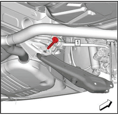
STABILIZER SHAFT LINK REPLACEMENT (AWD)
Removal Procedure
1. Raise and support the vehicle.
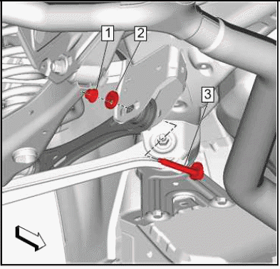
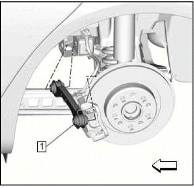
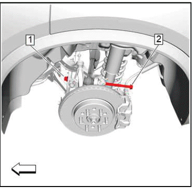
2.
.png)
NOTE: The tire and wheel assembly is removed for illustration purposes only.
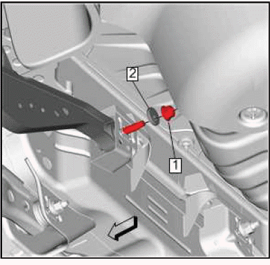
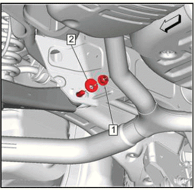
Rear Stabilizer Shaft Link Nut(1) - Remove.
3. Rear Stabilizer Shaft Link Bolt(2) - Remove.
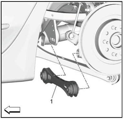
4.
.png)
Rear Stabilizer Shaft Link(1) - Remove.
Installation Procedure
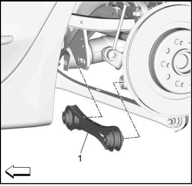
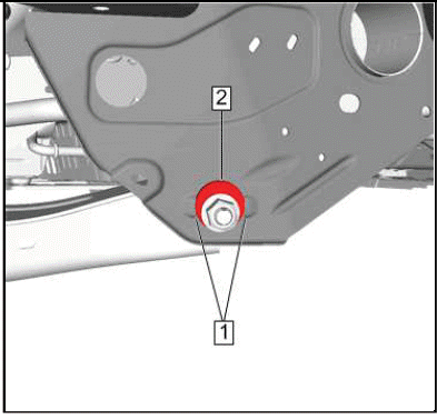
1.
.png)
Rear Stabilizer Shaft Link(1) - Install.
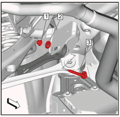
2.
.png)
CAUTION: Refer to Fastener Caution.
Rear Stabilizer Shaft Link Bolt(2) - Install and tighten 58 N.m (43 lb ft).
3. Rear Stabilizer Shaft Link Nut (1) - Install and tighten 58 N.m (43 lb ft).
4. Remove the support and lower the vehicle.
STABILIZER SHAFT LINK REPLACEMENT (FWD)
Removal Procedure
1. Raise and support the vehicle.
2.
.png)
Rear Stabilizer Shaft Link Nut(1)@Rear Stabilizer Shaft - Remove.
3. Rear Stabilizer Shaft Link Bolt(2)@Rear Stabilizer Shaft - Remove and DISCARD.
4.
.png)
Rear Stabilizer Shaft Link Nut(1)@Lower Control Arm - Remove.
5. Rear Stabilizer Shaft Link Bolt(2)@Lower Control Arm - Remove.
6.
.png)
Rear Stabilizer Shaft Link - Remove.
Installation Procedure
1.
.png)
Rear Stabilizer Shaft Link(1) - Install.
2.
.png)
Rear Stabilizer Shaft Link Bolt(2)@Lower Control Arm - Install.
CAUTION: Refer to Fastener Caution.
3. Rear Stabilizer Shaft Link Nut(1)@Lower Control Arm - Install and tighten 58 N.m (43 lb ft).
4.
.png)
CAUTION: This vehicle is equipped with torque-to-yield or single use fasteners. Install a NEW torque-to-yield or single use fastener when installing this component.
Failure to replace the torque-to-yield or single use fastener could cause damage to the vehicle or component.
Due to unknown shelf life of the NEW rear stabilizer shaft link bolt (2) adhesive patches, prepare the NEW bolt as follows:
- Remove all traces of the adhesive patches from the NEW rear stabilizer shaft link bolt (2).
- Clean the threads of the NEW bolt with denatured alcohol.
- Apply thread locking adhesive to the NEW rear stabilizer shaft link bolt (2). Adhesives, Fluids, Lubricants, and Sealers
- Ensure there are no gaps in the thread locking adhesive along the length of the filled area of the threads on the bolt shaft.
5. Rear Stabilizer Shaft Link Bolt@Rear Stabilizer Shaft(2) - Install NEW.
6. Rear Stabilizer Shaft Link Nut@Rear Stabilizer Shaft(1) - Install.
7. Rear Stabilizer Shaft Link Bolt@Rear Stabilizer Shaft(2) - Tighten.
- First Pass: 50 N.m (37 lb ft)
- Final Pass:60 - 75 degrees
8. Remove the support and lower the vehicle.
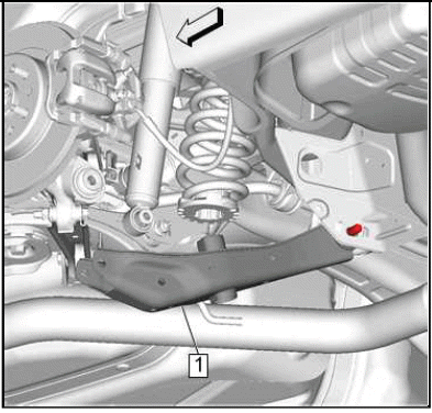
Rear Shock Absorber Mount Replacement
.png)
Preliminary Procedures
1. Remove the rear tire and wheel assembly.
2. Shock Absorber Replacement (GNC)Shock Absorber Replacement (GNQ).
- CAUTION: Refer to Fastener Caution.
Rear Shock Absorber NutTighten 20 N.m (15 lb ft) - Rear Suspension Mount Upper Cup
- Rear Shock Absorber Mount
- Rear Shock Absorber
SHOCK ABSORBER REPLACEMENT (GNC)
Removal Procedure
1. Remove the tire and wheel assembly.
2. Rear Wheelhouse Liner - Remove.
3.
.png)
{ If equipped }Electrical Connector(1)@Shock Absorber(2) - Disconnect.
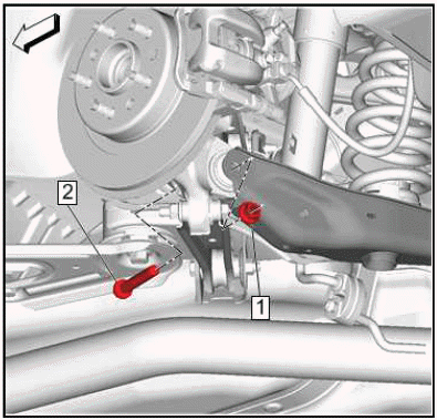
4.
.png)
5. Rear Shock Absorber Nut(1) - Remove.
6. Rear Shock Absorber Bolt(2) - Remove and DISCARD.
7.
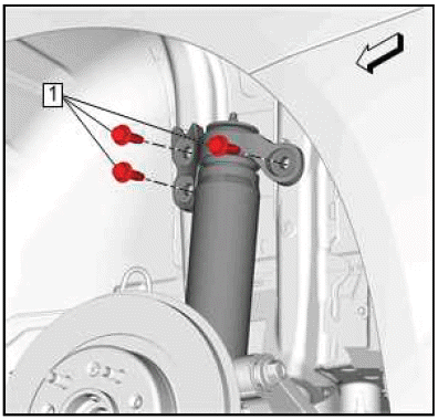
Rear Shock Absorber Bolt(1) - Remove[3x].
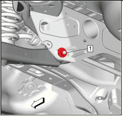
8.
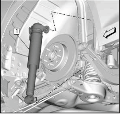
Rear Shock Absorber(1) - Remove.
Installation Procedure
1.
Rear Shock Absorber(1) - Install.
2.
.png)
CAUTION: Fastener Caution.
NOTE: Ensure jounce bumper and dust cover are secure within the top mount before tightening. If not properly secure, the jounce bumper and dust cover will fall down causing a click noise. When the top mount is fastened it secures the jounce bumper within the top mount.
Rear Shock Absorber Bolt(1) - Install and tighten[3x]58N.m (43 lb ft).
3. Tug downwards on the jounce bumper and dust cover. If the assembly falls out of the mount, remove the top mount fasteners and start over.
4.
.png)
CAUTION: This vehicle is equipped with torque-to-yield or single use
fasteners. Install a
NEW torque-to-yield or single use fastener when installing this component.
Failure to replace the torque-to-yield or single use fastener could cause
damage to the vehicle or component.
Rear Shock Absorber Bolt(2) - Install NEW.
5. Rear Shock Absorber Nut(1) - Install and tighten
- First Pass: 160 N.m (118 lb ft)
- Final Pass: 90 - 105 degrees
6.
.png)
{ If equipped }Electrical Connector(1)@Shock Absorber(2) - Connect.
7. Rear Wheelhouse Liner - Install.
8. Install the tire and wheel assembly.
SHOCK ABSORBER REPLACEMENT (GNQ)
Removal Procedure
1. Remove the rear tire and wheel assembly.
2. Rear Wheelhouse Liner - Remove.
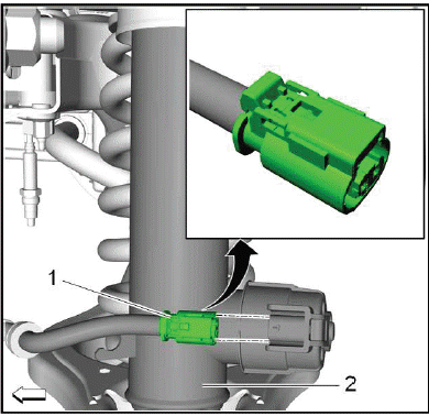
3.
.png)
If equipped Electrical Connector(1)@Shock Absorber(2) - Disconnect.
4. Using a suitable jack stand support the lower control arm.
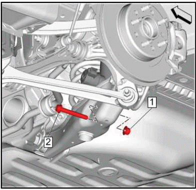
5.
.png)
Rear Shock Absorber Nut(1) - Remove.
6. Rear Shock Absorber Bolt(2) - Remove and DISCARD.
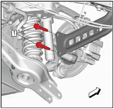
7.
.png)
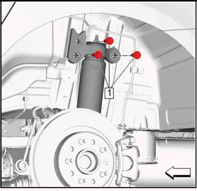
Rear Shock Absorber Bolt(1) - Remove[3x].
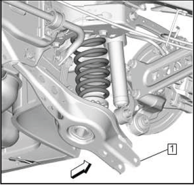
8.
.png)
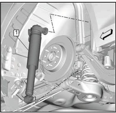
Rear Shock Absorber(1) - Remove.
Installation Procedure
1.
.png)
Rear Shock Absorber(1) - Install.
2.
CAUTION: Refer to Fastener Caution.
NOTE: Ensure jounce bumper and dust cover are secure within the top mount before tightening. If not properly secure, the jounce bumper and dust cover will fall down causing a click noise. When the top mount is fastened it secures the jounce bumper within the top mount.
Rear Shock Absorber Bolt(1) - Install and tighten[3x] 58 N.m (43 lb ft).
3. Tug downwards on the jounce bumper and dust cover. If the assembly falls out of the mount, remove the top mount fasteners and start over.
4.
CAUTION: This vehicle is equipped with torque-to-yield or single use fasteners. Install a NEW torque-to-yield or single use fastener when installing this component.
Failure to replace the torque-to-yield or single use fastener could cause damage to the vehicle or component.
Rear Shock Absorber Bolt(2) - Install NEW.
5. Rear Shock Absorber Nut(1) - Install.
Tighten
- First Pass: 100 N.m (74 lb ft)
- Final Pass: (90 - 105 degrees)
6. Remove the support from the lower control arm.
7.
If equipped Electrical Connector(1)@Shock Absorber(2) - Connect.
8. Rear Wheelhouse Liner - Install.
9. Install the rear tire and wheel assembly.
TRAILING ARM REPLACEMENT
Removal Procedure
1. Raise and support the vehicle.
2. Remove the rear tire and wheel assembly.
3. Rear Tire Front Air Deflector - Remove.
4. Support the rear suspension lower control arm with an appropriate jack stand.
5.
Lower the rear suspension lower control arm (1) to provide clearance for the rear suspension trailing arm bolt.
6.
Rear Suspension Trailing Arm Bolt(1) - Remove and DISCARD[2x].
7.
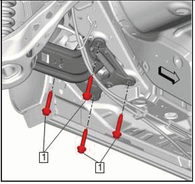
Rear Suspension Trailing Arm Bracket Bolt(1) - Remove and DISCARD[4x].
8.
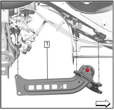
Rear Suspension Trailing Arm and Bracket(1) - Remove.
9. Mark the relationship between the rear suspension trailing arm (1) and the rear suspension trailing arm bracket.
10.
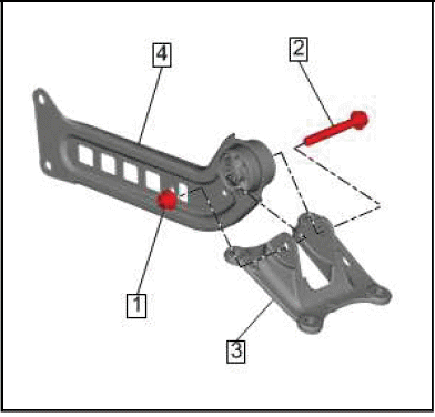
Rear Suspension Trailing Arm Bracket Nut(1) - Remove.
11. Rear Suspension Trailing Arm Bracket Bolt(2) - Remove and DISCARD.
12. Separate the rear suspension trailing arm bracket (3) from the rear suspension trailing arm (4).
Installation Procedure
1. If the rear suspension trailing arm or rear suspension trailing arm bracket are being replaced, transfer the relationship marks made on the old components to the new components.
2.

Position the rear suspension trailing arm (4) into the rear suspension trailing arm bracket (3) aligning the relationship marks previously made.
CAUTION: This vehicle is equipped with torque-to-yield or single use fasteners. Install a NEW torque-to-yield or single use fastener when installing this component.
Failure to replace the torque-to-yield or single use fastener could cause damage to the vehicle or component.
3. Rear Suspension Trailing Arm Bracket Bolt(2) - Install NEW.
CAUTION: Refer to Fastener Caution.
4. Rear Suspension Trailing Arm Bracket Nut(1) - Install and tighten.
- First Pass: 160 N.m (118 lb ft)
- Final Pass: (90 - 105 degrees)
5.
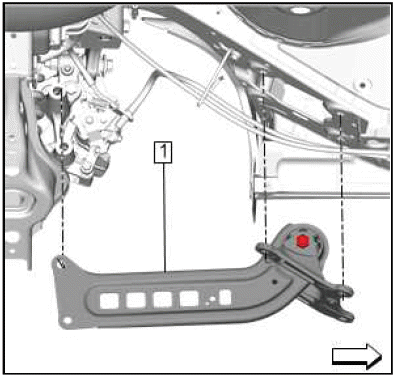
Rear Suspension Trailing Arm and Bracket(1) - Install.
6.
Rear Suspension Trailing Arm Bracket Bolt(1) - Install NEW and tighten[4x]
- First Pass: 100 N.m (74 lb ft)
- Final Pass: (90 - 105 degrees)
7.
Rear Suspension Trailing Arm Bolt(1) - Install NEW and tighten[2x]
- First Pass: 160 N.m (118 lb ft)
- Final Pass: (90 - 105 degrees)
8.
Raise the rear suspension lower control arm (1) back into position and install.
9. Remove the jack stand from underneath the rear suspension lower control arm.
10. Rear Tire Front Air Deflector - Install.
11. Install the rear tire and wheel assembly.
12. Remove the support and lower the vehicle.
Adjust Link Replacement (FWD)
Removal Procedure
1. Remove the tire and wheel assembly.
2. Rear Wheel Speed Sensor Replacement (Front Wheel Drive) Rear Wheel Speed Sensor Replacement (All Wheel Drive) - Remove.
3.
Rear Suspension Adjust Link Nut(1) - Remove.
4. Rear Suspension Adjust Link Cam(2) - Remove.
5.

Rear Suspension Adjust Link Inner Bolt(1) - Remove.
DISCARD the bolt.
6.
Rear Suspension Adjust Link Outer Nut(1) - Remove.
7. Remove the rear suspension outer bolt (2) and washer (3).
DISCARD the bolt.
8.
Rear Suspension Adjust Link(1) - Remove.
Installation Procedure
1.
Rear Suspension Adjust Link(1) - Install.
2.
CAUTION: This vehicle is equipped with torque-to-yield or single use fasteners. Install a NEW torque-to-yield or single use fastener when installing this component.
Failure to replace the torque-to-yield or single use fastener could cause damage to the vehicle or component.
Rear Suspension Adjust Link Inner Bolt(1) - Install.
Install a NEW bolt.
3.
CAUTION: Refer to Fastener Caution.
Rear Suspension Adjust Link Cam(2) - Install.
4. Rear Suspension Adjust Link Nut(1) - Install and tighten 90 N.m (66 lb ft).
5.
Install the rear suspension adjust link outer bolt (2) and washer (3).
Install a NEW bolt.
6. Rear Suspension Adjust Link Outer Nut(1) - Install.
Tighten
- First Pass: 160 N.m (118 lb ft)
- Final Pass: (90 - 105 degrees)
7. Check the rear wheel alignment.
ADJUST LINK REPLACEMENT (AWD)
Removal Procedure
1. Remove the tire and wheel assembly.
2.
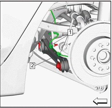
Rear Wheel Speed Sensor Harness(1)@Rear Suspension Adjust Link(2) - Separate.
3.
Remove the rear suspension adjust link outer bolt (1) and washer (2).
DISCARD the bolt.
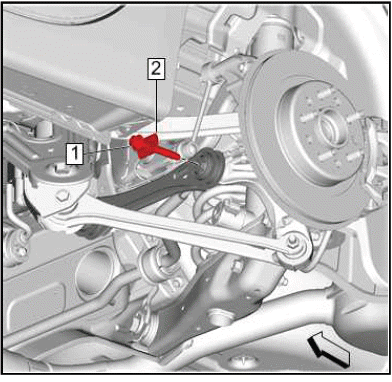
4.
Rear Suspension Adjust Link Nut(1) - Remove.
5. Rear Suspension Adjust Link Cam(2) - Remove.
6. Rear Suspension Adjust Link Inner Bolt - (3) Remove.
7.
Rear Suspension Adjust Link(1) - Remove.
Installation Procedure
1.
Rear Suspension Adjust Link(1) - Install.
2.
CAUTION: Refer to Fastener Caution.
Rear Suspension Adjust Link Inner Bolt(3) - Install.
3. Rear Suspension Adjust Link Cam(2) - Install.
4. Rear Suspension Adjust Link Nut(1) - Install.
Tighten
- First Pass: 80 N.m (59 lb ft)
- Final Pass: (30 - 45 degrees)
5.
Install a NEW rear suspension adjust link bolt (1) and washer (2).
Tighten
CAUTION: This vehicle is equipped with torque-to-yield or single use fasteners.
Install a NEW torque-to-yield or single use fastener when installing this component. Failure to replace the torque-to-yield or single use fastener could cause damage to the vehicle or component.
- First Pass: 100 N.m (74 lb ft)
- Final Pass: (90-105 degrees)
6.
Rear Wheel Speed Sensor Harness(1)@Rear Suspension Adjust Link(2) - Install.
7. Check the rear toe adjustment.
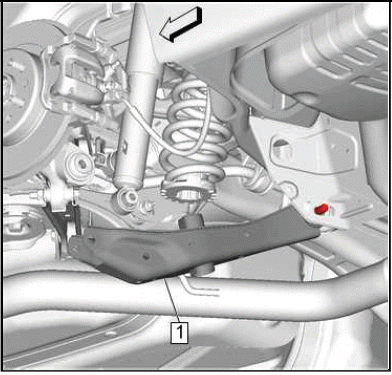
Rear Spring Replacement (FWD)
Removal Procedure
1. Remove the rear tire and wheel assembly.
2.
Rear Stabilizer Shaft Link Nut(1) - Remove.
3. Rear Stabilizer Shaft Link Bolt(2) - Remove.
4.
Rear Shock Absorber Nut(1) - Remove.
5. Rear Shock Absorber Bolt(2) - Remove.
DISCARD the bolt.
6. Support the lower control arm.
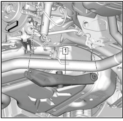
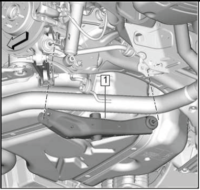
7.
Rear Suspension Lower Control Arm Nut(1) - Remove.
8. Rear Suspension Lower Control Arm Bolt(2) - Remove.
DISCARD the bolt.
9.
Lower the rear suspension lower control arm (1) to provide clearance for the rear coil spring.
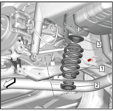
10.
Rear Coil Spring(1) - Remove.
11. Rear Coil Spring Lower Insulator(2) - Remove.
12. Rear Coil Spring Insulator(3) - Remove.
Installation Procedure
1.
Rear Coil Spring Lower Insulator(2) - Install.
2. Rear Coil Spring Insulator(3) - Install.
3. Rear Coil Spring(1) - Install.
4.
Raise the rear suspension lower control arm (1) back into position.
CAUTION: Refer to Fastener Caution.
CAUTION: This vehicle is equipped with torque-to-yield or single use fasteners. Install a NEW torque-to-yield or single use fastener when installing this component.
Failure to replace the torque-to-yield or single use fastener could cause damage to the vehicle or component.
5.
Rear Suspension Lower Control Arm Bolt(2) - Install.
Install a NEW bolt.
6. Rear Suspension Lower Control Arm Nut(1) - Install.
Tighten
- First Pass: 160 N.m (118 lb ft)
- Final Pass: (90 - 105 degrees)
7.
Rear Shock Absorber Bolt(2) - Install.
Install a NEW bolt.
8. Rear Shock Absorber Nut(1) - Install.
Tighten
- First Pass: 160 N.m (118 lb ft)
- Final Pass: (90 - 105 degrees)
9.
Rear Stabilizer Shaft Link Bolt(2) - Install.
10. Rear Stabilizer Shaft Link Nut(1) - Install.
Tighten 58 N.m (43 lb ft).
11. Remove the support from the rear suspension lower control arm.
12. Install the rear tire and wheel assembly.
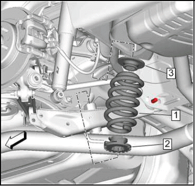
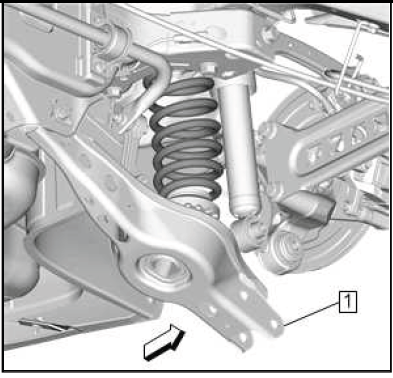
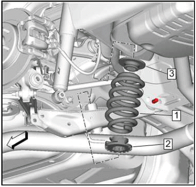
REAR SPRING REPLACEMENT (AWD)
Removal Procedure
1. Raise and support the vehicle.
2. Remove the rear tire and wheel assembly.
3. { If equipped }Wiring Harness@Rear Suspension Lower Control Arm - Separate.
4. Support the rear suspension lower control arm.
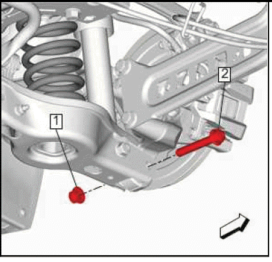
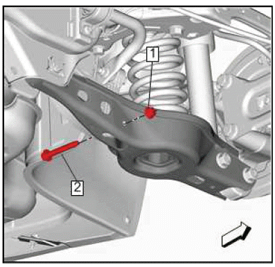
5.
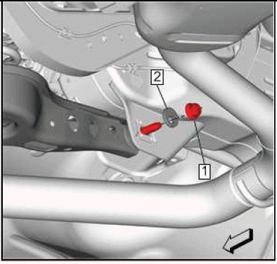
Rear Shock Absorber Nut(1) - Remove.
6. Rear Shock Absorber Bolt(2) - Remove and DISCARD.
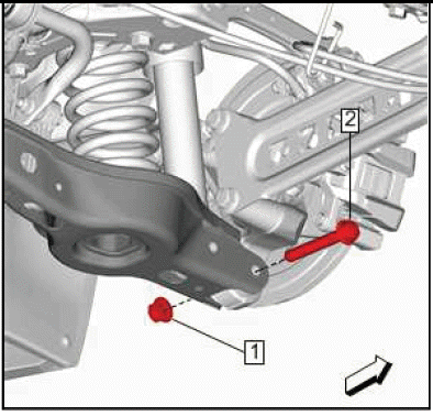
7.

Rear Suspension Lower Control Arm Outer Nut(1) - Remove.
8. Rear Suspension Lower Control Arm Outer Bolt(2) - Remove and DISCARD.
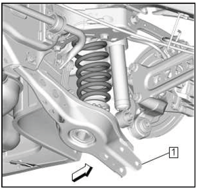
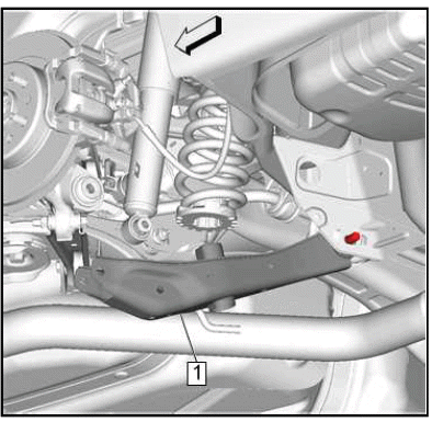
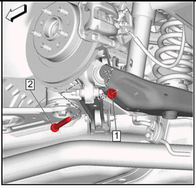
9.
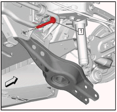
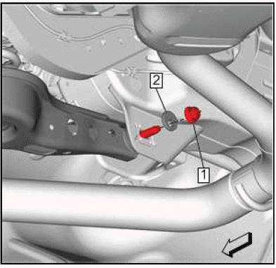
Rear Suspension Lower Control Arm Inner Nut(1) - Loosen.
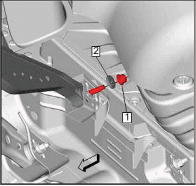
10.
Using a suitable flat bladed tool (1), separate the rear suspension lower control arm (2) from the rear suspension knuckle (3) as shown.
11.
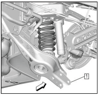
Lower the rear suspension lower control arm (1) to provide clearance for the rear coil spring.
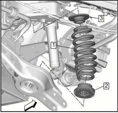
12.
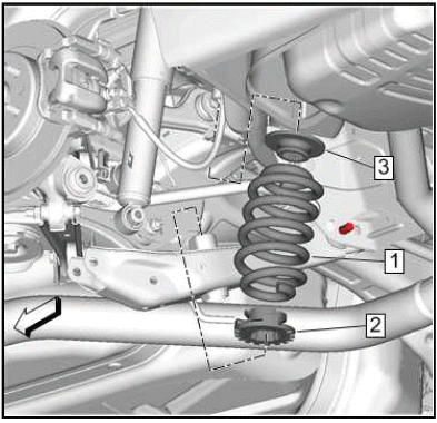
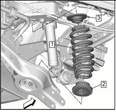
Rear Coil Spring(1) - Remove.
13. Rear Coil Spring Lower Insulator(2) - Remove.
14. Rear Coil Spring Insulator(3) - Remove.
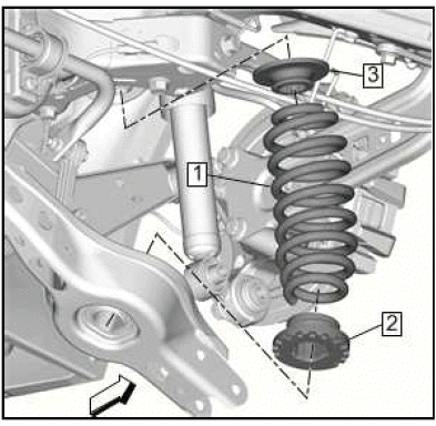
Installation Procedure
1.
Rear Coil Spring Insulator(3) - Install.
2. Rear Coil Spring Lower Insulator(2) - Install.
3. Rear Coil Spring(1) - Install.
4.
Raise the rear suspension lower control arm (1) back into position.
5.
CAUTION: This vehicle is equipped with torque-to-yield or single use fasteners. Install a NEW torque-to-yield or single use fastener when installing this component.
Failure to replace the torque-to-yield or single use fastener could cause damage to the vehicle or component.
Rear Suspension Lower Control Arm Outer Bolt(2) - Install NEW.
6. Rear Suspension Lower Control Arm Outer Nut(1) - Install.
7.
8. Rear Suspension Lower Control Arm Inner Nut(1) - Tighten.
9.

Rear Shock Absorber Bolt(2) - Install NEW.
10. Rear Shock Absorber Nut(1) - Install.
11. { If equipped }Wiring Harness@Rear Suspension Lower Control Arm - Install.
12. Remove the support from the rear suspension lower control arm.
13. Install the rear tire and wheel assembly.
14. Remove the support and lower the vehicle.
15. Verify the rear camber specifications and adjust as necessary.
Rear Suspension Upper Lateral Link Replacement (FWD)
Removal Procedure
1. Remove the tire and wheel assembly.
2. { If equipped }Rear Suspension Position Ball Socket @Rear Suspension Upper Lateral Link - Disconnect.
3.
Rear Suspension Upper Lateral Link Nut(1) - Remove.
4. Rear suspension upper lateral link bolt (2) and washer (3) - Remove DISCARD the bolt.
5.
Rear Suspension Upper Lateral Link Inner Bolt(1) - Remove and DISCARD.
6.
Rear Suspension Upper Lateral Link - Remove.
Installation Procedure
1.
Rear Suspension Upper Lateral Link(1) - Install.
2.
CAUTION: Refer to Fastener Caution.
CAUTION: This vehicle is equipped with torque-to-yield or single use fasteners. Install a NEW torque-to-yield or single use fastener when installing this component.
Failure to replace the torque-to-yield or single use fastener could cause damage to the vehicle or component.
Rear suspension upper lateral link bolt (2) and washer (3) - Install a NEW bolt.
3. Rear Suspension Upper Lateral Link Nut(1) - Install.
Tighten
- First Pass: 160 N.m (118 lb ft)
- Final Pass: (90-105 degrees)
4.
Rear Suspension Upper Lateral Link Inner Bolt(1) - Install a NEW bolt.
Tighten
- First Pass: 160 N.m (118 lb ft)
- Final Pass: (90-105 degrees)
5. { If equipped }Rear Suspension Position Ball Socket @Rear Suspension Upper Lateral Link - Connect.
6. Lower the vehicle.
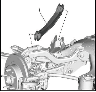
REAR SUSPENSION UPPER LATERAL LINK REPLACEMENT (AWD)
Removal Procedure
1. Raise and support the vehicle.
2. Lower the rear suspension cradle.
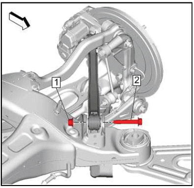
3.
Rear Suspension Upper Control Arm Inner Nut(1) - Remove.
4. Rear Suspension Upper Control Arm Inner Bolt(2) - Remove and DISCARD.
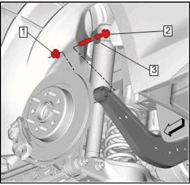
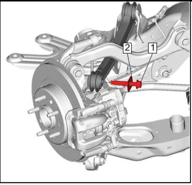
5.
Rear Suspension Upper Control Arm Outer Nut(1) - Remove.
6. Rear Suspension Upper Control Arm Outer Bolt(2) - Remove and DISCARD.
7.
Rear Suspension Upper Lateral Link(1) - Remove.
Installation Procedure
1.
Rear Suspension Upper Lateral Link(1) - Install.
2.
CAUTION: This vehicle is equipped with torque-to-yield or single use fasteners. Install a NEW torque-to-yield or single use fastener when installing this component.
Failure to replace the torque-to-yield or single use fastener could cause damage to the vehicle or component.
Rear Suspension Upper Control Arm Outer Bolt(2) - Install NEW.
CAUTION: Refer to Fastener Caution.
3. Rear Suspension Upper Control Arm Outer Nut(1) - Install and tighten.
- First Pass: 100 N.m (74 lb ft)
- Final Pass: (90 - 105 degrees)
4.
Rear Suspension Upper Control Arm Inner Bolt(2) - Install NEW.
5. Rear Suspension Upper Control Arm Inner Nut(1) - Install and hand tighten.
6. Rear Suspension Upper Control Arm Inner Bolt(2) - Tighten.
- First Pass: 100 N.m (74 lb ft)
- Final Pass: (90 - 105 degrees)
7. Raise the rear suspension cradle to its original position.
8. Remove the support and lower the vehicle.
REAR SUSPENSION UPPER TRAILING LINK REPLACEMENT
Removal Procedure
1. Raise and support the vehicle.
2. Lower the rear suspension cradle.
3.
Rear Suspension Trailing Arm Nut(1) - Remove.
4. Rear Suspension Trailing Arm Bolt(2) - Remove and DISCARD.
5.
Rear Suspension Trailing Arm Bracket Bolt(1) - Remove and DISCARD.
6. Rear Suspension Trailing Arm Washer(2) - Remove.
7.
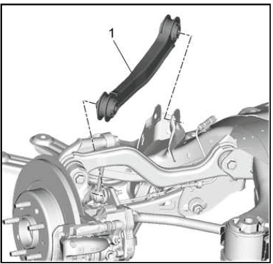
Rear Suspension Upper Trailing Link(1) - Remove.
Installation Procedure
1.
Rear Suspension Upper Trailing Link(1) - Install.
2.
CAUTION: This vehicle is equipped with torque-to-yield or single use fasteners. Install a NEW torque-to-yield or single use fastener when installing this component.
Failure to replace the torque-to-yield or single use fastener could cause damage to the vehicle or component.
Rear Suspension Trailing Arm Bolt(2) - Install NEW.
3. Rear Suspension Trailing Arm Nut(1) - Install and hand tighten.
CAUTION: Refer to Fastener Caution.
4. Rear Suspension Trailing Arm Bolt(2) - Tighten.
- First Pass: 100 N.m (74 lb ft)
- Final Pass: (90 - 105 degrees)
5.
Rear Suspension Trailing Arm Washer(2) - Install.
6. Rear Suspension Trailing Arm Bracket Bolt(1) - Install NEW and tighten.
- First Pass: 100 N.m (74 lb ft)
- Final Pass: (90 - 105 degrees)
7. Raise the rear suspension cradle to its original position.
8. Remove the support and lower the vehicle.
Rear Suspension Lower Trailing Link Replacement
Removal Procedure
1. Raise and support the vehicle.
2. Remove the rear tire and wheel assembly.
3.
Rear Suspension Trailing Arm Nut(1) - Remove.
4. Rear Suspension Trailing Arm Bolt(2) - Remove and DISCARD.
5.
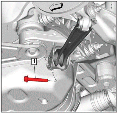
Rear Suspension Trailing Arm Bolt(1) - Remove and DISCARD.
6.
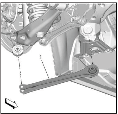
Rear Suspension Lower Trailing Link(1) - Remove.
Installation Procedure
1.
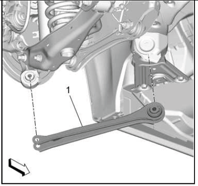
Rear Suspension Lower Trailing Link(1) - Install.
2.
CAUTION: Refer to Fastener Caution.
CAUTION: This vehicle is equipped with torque-to-yield or single use fasteners. Install a NEW torque-to-yield or single use fastener when installing this component.
Failure to replace the torque-to-yield or single use fastener could cause damage to the vehicle or component.
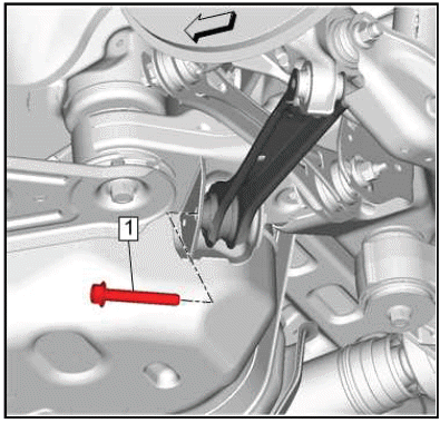
Rear Suspension Trailing Arm Bolt(1) - Install NEW and tighten.
- First Pass: 100 N.m (74 lb ft)
- Final Pass: (90 - 105 degrees)
3.
Rear Suspension Trailing Arm Bolt(2) - Install NEW.
4. Rear Suspension Trailing Arm Nut(1) - Install and hand tighten.
5. Rear Suspension Trailing Arm Bolt(2) - Tighten
- First Pass: 100 N.m (74 lb ft)
- Final Pass: (90 - 105 degrees)
6. Install the rear tire and wheel assembly.
7. Remove the support and lower the vehicle.
LOWER CONTROL ARM REPLACEMENT (FWD)
Removal Procedure
1. Remove the rear tire and wheel assembly.
2. Support the rear suspension lower control arm.
3.
Rear Stabilizer Shaft Link Nut(1) - Remove.
4. Rear Stabilizer Shaft Link Bolt(2) - Remove.
5.
Rear Shock Absorber Nut(1) - Remove.
6. Rear Shock Absorber Bolt(2) - Remove and DISCARD.
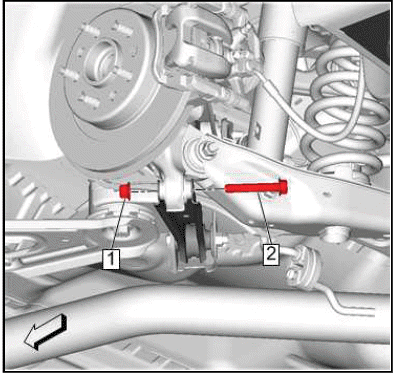
7.
Rear Suspension Lower Control Arm Outer Nut(1) - Remove.
8. Rear Suspension Lower Control Arm Outer Bolt(2) - Remove and DISCARD.
9.
Rear Suspension Lower Control Arm Inner Nut(1) - Remove.
10. Rear Suspension Lower Control Arm Adjust Cam(2) - Remove.
11.
Lower the rear suspension lower control arm (1) to provide clearance for the rear coil spring.
12.
Rear Coil Spring (1) - Remove.
13. Rear Coil Spring Lower Insulator (2) - Remove.
14. Rear Coil Spring Insulator (3) - Remove.
15.
Rear Suspension Lower Control Arm Adjust Bolt(1) - Remove.
16.
Rear Suspension Lower Control Arm(1) - Remove.
Installation Procedure
1.
Rear Suspension Lower Control Arm(1) - Install.
2.
Rear Suspension Lower Control Arm Adjust Bolt(1) - Install.
3.
Rear Coil Spring Lower Insulator (2) - Install.
4. Rear Coil Spring (1) - Install.
5. Rear Coil Spring Insulator (3) - Install.
6.
Raise the rear suspension lower control arm (1) back into position.
7.
CAUTION: Refer to Fastener Caution.
Rear Suspension Lower Control Arm Adjust Cam(2) - Install.
8. Rear Suspension Lower Control Arm Inner Nut(1) - Install and tighten 90 N.m (66 lb ft).
9.
CAUTION: This vehicle is equipped with torque-to-yield or single use fasteners. Install a NEW torque-to-yield or single use fastener when installing this component.
Failure to replace the torque-to-yield or single use fastener could cause damage to the vehicle or component.
Rear Suspension Lower Control Arm Outer Bolt(2) - Install a NEW bolt.
10. Rear Suspension Lower Control Arm Outer Nut(1) - Install.
Tighten
- First Pass: 160 N.m (118 lb ft)N.m
- Final Pass: (90-105 degrees)
11.

Rear Shock Absorber Bolt(2) - Install a NEW bolt.
12. Rear Shock Absorber Nut(1) - Install.
Tighten
- First Pass: 160 N.m (118 lb ft)N.m
- Final Pass: (90-105 degrees)
13.
Rear Stabilizer Shaft Link Bolt(2) - Install.
14. Rear Stabilizer Shaft Link Nut(1) - Install and tighten 58 N.m (43 lb ft).
15. Remove the support from the rear suspension lower control arm.
16. Install the rear tire and wheel assembly.
17. Verify the rear camber specifications and adjust as necessary.
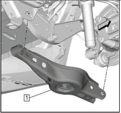
LOWER CONTROL ARM REPLACEMENT (AWD)
Removal Procedure
1. Raise and support the vehicle.
2. Remove the rear tire and wheel assembly.
3. { If equipped }Wiring Harness@Rear Suspension Lower Control Arm - Separate.
4. Support the rear suspension lower control arm.
5.
Rear Shock Absorber Nut(1) - Remove.
6. Rear Shock Absorber Bolt(2) - Remove and DISCARD.
7.
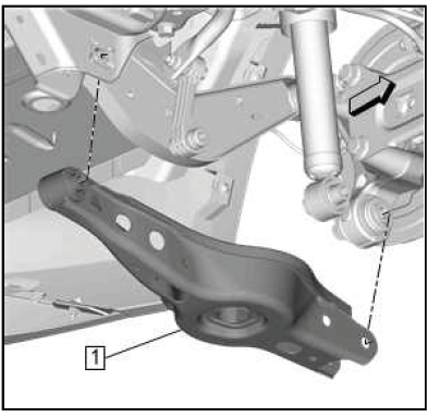
Rear Suspension Lower Control Arm Outer Nut(1) - Remove.
8. Rear Suspension Lower Control Arm Outer Bolt(2) - Remove and DISCARD.
9.
Rear Suspension Lower Control Arm Inner Nut(1) - Remove.
10. Rear Suspension Lower Control Arm Adjust Cam(2) - Remove.
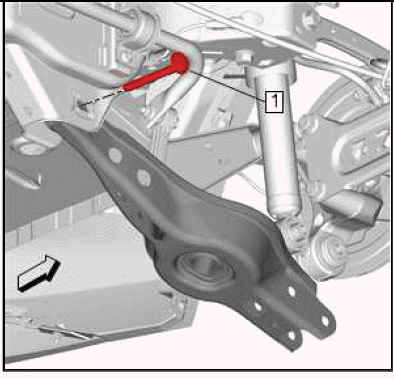
11.
Using a suitable flat bladed tool (1), separate the rear suspension lower control arm (2) from the rear suspension knuckle (3) as shown.
12.
Lower the rear suspension lower control arm (1) to provide clearance for the rear coil spring.
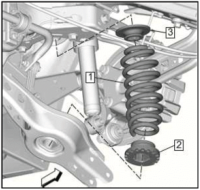
13.
Rear Coil Spring(1) - Remove.
14. Rear Coil Spring Lower Insulator(2) - Remove.
15. Rear Coil Spring Insulator(3) - Remove.
16.

Rear Suspension Lower Control Arm Adjuster Bolt(1) - Remove.
17.
Rear Suspension Lower Control Arm(1) - Remove.
Installation Procedure
1.
Rear Suspension Lower Control Arm(1) - Install.
2.
Rear Suspension Lower Control Arm Adjuster Bolt(1) - Install.
3.

NOTE: Ensure the proper rear suspension lower control arm adjuster bolt and rear suspension lower control arm adjust cam installation and orientation.
Install the rear suspension lower control arm adjuster bolt so the rear suspension lower control arm adjust cam does not overlap the raised structure on the cradle (1), and the rear suspension lower control arm adjust cam scribe marks face 9 and 3 o'clock (2).
4.
Rear Suspension Lower Control Arm Adjust Cam(2) - Install.
5. Rear Suspension Lower Control Arm Inner Nut(1) - Install and hand tighten.
6.
NOTE: Ensure the proper rear suspension lower control arm inner nut and rear suspension lower control arm adjust cam installation and orientation.
Install the rear suspension lower control arm inner nut so the rear suspension lower control arm adjust cam does not overlap the raised structure on the cradle (1), and the cam scribe marks face 9 and 3 o'clock (2).
7.
Rear Coil Spring Insulator(3) - Install.
8. Rear Coil Spring Lower Insulator(2) - Install.
9. Rear Coil Spring(1) - Install.
10.
Raise the rear suspension lower control arm (1) back into position.
11.
CAUTION: This vehicle is equipped with torque-to-yield or single use fasteners. Install a NEW torque-to-yield or single use fastener when installing this component.
Failure to replace the torque-to-yield or single use fastener could cause damage to the vehicle or component.
Rear Suspension Lower Control Arm Outer Bolt(2) - Install NEW.
CAUTION: Refer to Fastener Caution.
12. Rear Suspension Lower Control Arm Outer Nut(1) - Install and tighten.
- First Pass: 150 N.m (111 lb ft)
- Final Pass: (90-105 degrees)
13.
Rear Suspension Lower Control Arm Inner Nut(1) - Tighten 160 N.m (118 lb ft).
14.

Rear Shock Absorber Bolt(2) - Install NEW.
15. Rear Shock Absorber Nut(1) - Install.
16. { If equipped }Wiring Harness@Rear Suspension Lower Control Arm - Install.
17. Remove the support from the rear suspension lower control arm.
18. Install the rear tire and wheel assembly.
19. Remove the support and lower the vehicle.
20. Verify the rear camber specifications and adjust as necessary.
WHEEL STUD REPLACEMENT
Special Tools
CH-43631 Ball Joint Remover
Equivalent regional tools: Special Tools.
Removal Procedure
1. Remove the rear tire and wheel assembly.
2. Rear Wheel Bearing and Hub Assembly - Remove.
3.
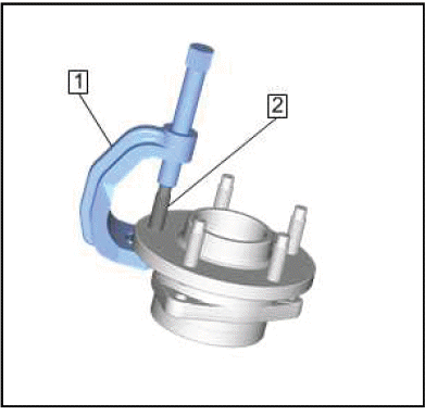
Position the wheel bearing and hub assembly in a suitable vise.
4. Use the CH-43631 ball joint remover (1) to remove and discard the wheel stud (2).
Installation Procedure
1.
Install the NEW wheel stud (1) into the wheel bearing hub flange (2).
2. Add enough washers (3) in order to draw the stud into the hub flange (2).
3. Install the wheel nut (4) against the washers (3).
4. Tighten the wheel nut (4) until the head of the wheel stud (1) is fully seated against the back of the bearing hub flange (2).
5. Remove the wheel nut (4) and the washers (3).
6. Remove the wheel bearing and hub assembly from the vise.
7. Rear Wheel Bearing and Hub Assembly - Install.
8. Install the rear tire and wheel assembly.
READ NEXT:
 Description and Operation
REAR SUSPENSION DESCRIPTION AND OPERATION
The rear suspension system on this vehicle is of the independent link type.
Rear suspension adjustment is achieved
through adjustable toe links and lower con
Suspension General Diagnosis
SPECIFICATIONS
TRIM HEIGHT SPECIFICATIONS
Trim Height Specifications (P-R Height) - Hatchback
NOTE: For 0% option vehicles add 1 mm to front and rear suspension
values.
For 100% option vehicles subt
Tire Pressure Monitoring System
SPECIFICATIONS
FASTENER SPECIFICATIONS
Reusable Threaded Fastener Tightening Specifications
NOTE:
All fasteners listed in this table can be reused after removal.
SEE MORE:
Steering Gear Preload Adjustment Caution
CAUTION: Do not change the steering gear preload adjustment before
moving the
inner tie rod from the steering gear. Changing the steering gear preload
adjustment before moving the inner tie rod could result in damage to the
pinion and the steering gear.
STEERING WHEEL IN THE FULL TURN POSITION CAUT
Diagnostic Information and Procedures
DTC B1395
Diagnostic Instructions
Perform the Diagnostic System Check - Vehicle prior to using this
diagnostic procedure.
Review Strategy Based Diagnosis for an overview of the diagnostic
approach.
Diagnostic Procedure Instructions provides an overview of each
diagnostic category.
DTC Des
