Opel Insignia: Repair Instructions - Off Vehicle
Draining Fluids and Oil Filter Removal
1.
.png)
Remove the oil filter (1). Remove the oil pan drain plug and allow the oil to drain out.
2. Clean the oil filter housing in the engine block.
CAUTION: Refer to Fastener Caution.
3. Install the oil pan drain plug and tighten to 25 N.m (18 lb ft).
4. If cleaning or repairing the engine block, it is not necessary to reinstall the plug.
CRANKSHAFT BALANCER REMOVAL
Special Tools
- EN-38416-2 Crankshaft Button
- EN-41816 Crankshaft Balancer Remover
- EN-41816-2 Crankshaft End Protector
- EN - 51760 Flywheel Holding Tool
For equivalent regional tools, refer to Special Tools.
1.
.png)
To prevent crankshaft rotation, install EN-51760 holding tool (2) and starter motor bolts (1) at the starter motor location and engaging the flywheel.
2.
.png)
Remove and discard the crankshaft balancer bolt (1) and washer.
NOTE: When necessary, EN-38416-2 button can be used instead of EN-41816-2 protector.
3. Install EN-41816-2 protector (3) to protect the crankshaft end during balancer removal.
NOTE: EN-51577-1 remover (5) can be used alternatively for EN-41816 remover (4).
4. Using EN-41816 remover (4), remove the balancer (2).
5. Remove the special tools.
AUTOMATIC TRANSMISSION FLEX PLATE REMOVAL
Special Tools
EN-51760 Flywheel Holding Tool
For equivalent regional tools, refer to Special Tools.
1.
.png)
To prevent crankshaft rotation, install EN-51760 holding tool (2) and starter motor bolts (1) at the starter motor location and engaging the flywheel.
2.
.png)
Remove and discard the flywheel attaching bolts (1).
3. Remove the flywheel (2).
4. Remove EN 51760 holding tool.
INTAKE MANIFOLD REMOVAL
1.
.png)
CAUTION: Never attempt to remove the intake manifold from a hot engine, allow the engine to cool to ambient temperature. The intake manifold can be damaged if it is removed when the engine is hot.
Remove the EVAP canister valve (1).
2.
.png)
Remove the throttle body bolts (1).
3. Remove the throttle body (2) and seal (3).
4.
.png)
Remove the fuel pump cover bolts and cover.
5.
.png)
WARNING: The noise cancelling foam component MUST be replaced if it has been exposed to engine fluids. Failure to replace the noise cancelling foam component that has been exposed to engine fluids may result in an engine fire resulting in catastrophic engine damage, and possible injury or death.
Remove the fuel pump insulator (6).
WARNING: Fuel that flows out at high pressure can cause serious injury to the skin and eyes. ALWAYS depressurize the fuel system before removing components that are under high fuel pressure.
6. Remove and discard the fuel feed intermediate pipe (5).
CAUTION: Alternately loosen the fuel pump bolts one turn at a time until the pump is fully disengaged from fuel pump lifter follower. Trying to remove the pump bolts without even side-to-side loosening may result in pump plunger damage.
7. Remove and discard the fuel pump bolts.
8. Remove the fuel pump (4), O-ring (3), and gasket (2). Discard the O-ring and gasket.
9. Remove the valve lifter follower (1).
10.
.png)
Remove the MAP sensor (1) and bolt (2).
11.
.png)
Remove the intake manifold retaining bolts (2, 4).
12. Remove the intake manifold (3) and gasket (1).
13. If the intake manifold needs to be replaced, transfer the throttle body to the new intake manifold.
CAMSHAFT COVER AND COMPRESSOR AIR INTAKE TURBOCHARGER REMOVAL (2ND DESIGN TAMPER-PROOF PCV SYSTEM)
Turbocharger Component Removal
.png)
Turbocharger Component Removal
- Turbocharger Heat Shield Bolt [3x]
NOTE: In the event that a bolt breaks upon removal of components, perform an extraction of the broken bolt. - Turbocharger Heat Shield
- Turbocharger Wastegate Actuator Arm Retainer
- Turbocharger Wastegate Actuator Bolt [2x]
- Turbocharger Wastegate Actuator
- Turbocharger Coolant Return Pipe Bolt
NOTE: One bolt retains the turbocharger coolant return pipe and the camshaft cover heat shield at the same location. - Turbocharger Coolant Return Pipe Bolt
- Turbocharger Coolant Return Pipe
Procedure
Disconnect the turbocharger coolant return pipe from the air bleed hose. - Turbocharger Coolant Return Pipe Washer [2x]
NOTE: Discard the washers. - Turbocharger Coolant Feed Pipe Bolt
- Turbocharger Coolant Feed Pipe Bolt [2x]
- Turbocharger Coolant Feed Pipe
Procedure
Disconnect the turbocharger coolant feed pipe hose from the engine oil cooler. - Turbocharger Coolant Feed Pipe Gasket
NOTE: Discard the gasket. - Turbocharger Coolant Feed Pipe Washer [2x]
NOTE: Discard the washers. - Turbocharger Wastegate Regulator Solenoid Valve Bolt
- Turbocharger Wastegate Regulator Solenoid Valve
Procedure
Disconnect the turbocharger wastegate regulator solenoid valve hoses from the turbocharger. - Turbocharger Air Bypass Valve Solenoid Bolt [3x]
- Turbocharger Air Bypass Valve Solenoid
Camshaft Cover Component Removal
.png)
Camshaft Cover Component Removal
- Engine Coolant Air Bleed Pipe Bolt
- Engine Coolant Air Bleed Pipe
- Engine Coolant Air Bleed Pipe O-Ring
NOTE: Inspect O-ring and discard if necessary. - Camshaft Cover Heat Shield Bolt [3x]
NOTE: An additional bolt retains the camshaft cover heat shield and the turbocharger coolant return pipe. - Camshaft Cover Heat Shield
- Oil Level Indicator
NOTE: Inspect and replace the oil indicator O-ring seals, if necessary. - Engine Lift Rear Bracket Bolt [2x]
- Engine Lift Rear Bracket
- Engine Lift Front Bracket Bolt [2x]
- Engine Lift Front Bracket
- Ignition Coil Bolt [4x]
- Ignition Coil [4x]
- Camshaft Position Actuator Solenoid Valve Bolt
- Camshaft Position Actuator Solenoid Valve - Intake
- Camshaft Position Actuator Solenoid Valve Bolt
- Camshaft Position Actuator Solenoid Valve - Exhaust
- Vacuum Pump Bolt
- Vacuum Pump Bolt [2x]
- Vacuum Pump
- Vacuum Pump Gasket
NOTE: Discard the gasket.
Camshaft Cover and Turbocharger Removal
.png)
Camshaft Cover and Turbocharger Removal
- Turbocharger Oil Feed Pipe Bolt [2x]
- Turbocharger Oil Return Pipe Bolt [2x]
- Turbocharger Nut [4x]
NOTE: Discard the nuts. - Camshaft Cover Bolt [4x]
- Camshaft Cover Bolt [17x]
- Camshaft Cover & Positive Crankcase Ventilation Tube & Turbocharger
NOTE: The tamper-proof positive crankcase ventilation system includes components that may be replaced if necessary. The system may include an outlet duct connected to the end of the Positive Crankcase Ventilation Tube. If any component is suspect, refer to the inspection procedures and individual replacement procedures before attempting to disassemble the PCV system. Be careful when moving the assembled components with tamper-proof fittings to avoid stress on the connections.NOTE: The assembly is removed with the oil return pipe and oil feed pipe attached at the turbocharger.
Procedure- The assistance of a second technician may be necessary to support and move the assembly during removal.
- Ensure a large enough clean area is prepared before removing the assembly.
- Refer to Camshaft Cover and Compressor Air Intake Turbocharger Cleaning and Inspection.
- Camshaft Cover Gasket
NOTE: Ensure all camshaft cover gaskets, including the inner gaskets, are removed and discarded. - Turbocharger Oil Feed Pipe Bolt
- Turbocharger Oil Feed Pipe
- Turbocharger Oil Feed Pipe Washer [2x]
NOTE: Discard the washers. - Turbocharger Oil Feed Pipe Gasket
NOTE: Discard the gasket. - Turbocharger Oil Return Pipe Bolt [2x]
- Turbocharger Oil Return Pipe
- Turbocharger Oil Return Pipe Gasket
NOTE: Discard the gasket. - Turbocharger Oil Return Pipe Gasket
NOTE: Discard the gasket.
Turbocharger Removal (1ST Design Tamper-Proof PCV System)
1.
.png)
NOTE: In the event that a bolt breaks upon removal of components, perform an extraction of the broken bolt.
Remove the turbocharger heat shield bolts (1, 3).
2. Remove the turbocharger heat shield (2).
3.
.png)
Remove the turbocharger wastegate actuator arm retainer (3).
4. Remove the turbocharger wastegate actuator bolts (1) and actuator (2).
5.
.png)
Remove the camshaft cover heat shield bolt (1) that retains the turbocharger coolant return pipe (2) at the camshaft cover.
6. Disconnect the turbocharger coolant return pipe from the air bleed hose.
7. Remove the turbocharger coolant return pipe bolt (3).
8. Remove the turbocharger coolant return pipe (2) and washers (4, 5). Discard the washers.
9.
.png)
Remove the turbocharger coolant feed pipe bolts (1, 3).
10. Disconnect the turbocharger coolant feed pipe hose from the engine oil cooler.
11. Remove the turbocharger coolant feed pipe gasket (4) and discard.
12. Remove the turbocharger coolant feed pipe (5) and washers (2). Discard the washers.
13.
.png)
Disconnect the turbocharger wastegate regulator solenoid valve hoses from the turbocharger.
14. Remove the turbocharger wastegate regulator solenoid valve bracket bolt (2).
15. Remove the turbocharger wastegate regulator solenoid valve (1).
16.
.png)
Remove the turbocharger bypass valve solenoid bolts (1).
17. Remove the turbocharger bypass valve solenoid (2).
18.
.png)
NOTE: Do not disturb the joint between the PCV hose and PCV hose fitting at the turbocharger. This is a permanent connection.
Remove the PCV hose fitting bolt (2). Disconnect the PCV hose fitting (1) with the PCV hose attached from the turbocharger.
19.
.png)
Remove the turbocharger nuts (2) and discard.
20. Remove the turbocharger oil feed and return pipe bolts (6) at the engine block.
21. Remove the turbocharger (1) with the oil return pipe and oil feed pipe attached.
22. Remove the turbocharger oil feed and oil return pipe gaskets (4, 5) and discard.
23. Remove the turbocharger gasket (3) and discard.
24.
.png)
Remove the turbocharger oil feed pipe bolt (1) from the turbocharger.
25. Remove the turbocharger oil feed pipe (2) and washers (3). Discard the washers.
26. Remove the turbocharger oil return pipe bolts (6).
27. Remove the turbocharger oil return pipe (5).
28. Remove and discard the turbocharger oil return pipe gasket (4).
29. Clean and inspect the turbocharger and components. Refer to Camshaft Cover and Compressor Air Intake Turbocharger Cleaning and Inspection.
EXHAUST MANIFOLD REMOVAL
1.
.png)
NOTE: In the event that a bolt breaks upon removal of components, perform an extraction of the broken bolt.
Remove the exhaust manifold heat shield bolts (2).
2. Remove the exhaust manifold heat shield (1).
3.
.png)
Remove the exhaust manifold brace nuts (1) and discard.
4. Remove the exhaust manifold brace bolts (3).
5. Remove the exhaust manifold brace (2).
6.
.png)
Remove and discard the exhaust manifold to cylinder head bolts (3).
7. Remove the exhaust manifold (1).
8. Remove and discard the exhaust manifold gasket (2).
9. Clean all of the sealing surfaces.
FUEL RAIL AND INJECTORS REMOVAL
Special Tools
EN-49248 Fuel Rail Assembly Remover
For equivalent regional tools, refer to Special Tools
1.
.png)
WARNING: The noise cancelling foam component MUST be replaced if it has been exposed to engine fluids. Failure to replace the noise cancelling foam component that has been exposed to engine fluids may result in an engine fire resulting in catastrophic engine damage, and possible injury or death.
Remove the fuel injection fuel rail noise shield (1).
2.
.png)
Disconnect the electrical harness from the fuel rail harness connection.
NOTE: Fuel rail bolts are captured in the fuel rail assembly
- Ensure the bolt is completely loosened, and the threads are no longer engaged.
- Use a suitable tool to apply enough force to pull the bolt straight out of the fuel rail.
3. Remove the fuel rail assembly retaining bolts.
NOTE: Use care to avoid contact with the fuel rail harness during special tool installation and fuel rail removal.
4. Install EN-49248 studs (1) into the 2 outermost fuel rail assembly retaining bolt locations. Tighten the studs to 22 N.m (16 lb ft).
5. Install EN-49248 remover (2) onto each stud, and engage the hooks to the fuel rail. Install the nuts (3) retaining the remover onto the studs and tighten until snug.
6.
.png)
CAUTION:
- Remove the fuel rail assembly carefully in order to prevent damage
to the
injector electrical connector terminals and the injector spray tips.
Support the fuel rail after the fuel rail is removed in order to avoid damaging the fuel rail components.
- Cap the fittings and plug the holes when servicing the fuel system in order to prevent dirt and other contaminants from entering open pipes and passages.
NOTE: EN-49248 will assist in the proper removal of the fuel rail assembly. Ensure that the following conditions are met:
- Turn the handles simultaneously in order to pull the fuel rail straight out along the fuel injector axis.
- DO NOT twist when pulling out on the fuel rail and injector assembly.
Using EN-49248 remover, remove the fuel rail assembly.
CAMSHAFT COVER REMOVAL (1ST DESIGN TAMPER-PROOF PCV SYSTEM)
1.
.png)
Remove the engine coolant air bleed pipe bolt (1).
2. Remove the engine coolant air bleed pipe (2), hose (3), and O-ring (4). Inspect O-ring and discard if necessary.
3.
.png)
Remove the oil level indicator (3). Inspect and replace the oil indicator O-ring seals (4), if necessary.
4. Remove the camshaft cover heat shield (2) and bolts (1).
5.
.png)
Remove the rear lift bracket (1) and bolts (2).
6.
.png)
Remove the front lift bracket (2) and bolts (1).
7.
.png)
Remove the ignition coils (2) and bolts (1).
8.
.png)
Remove the camshaft position actuator solenoid valves (2) and bolts (1).
9.
.png)
Remove the vacuum assembly (2) and bolts (1).
10. Remove the vacuum assembly gasket (3) and discard.
11.
.png)
Remove the camshaft cover bolts (1, 3) and camshaft cover (2).
NOTE: Ensure all camshaft cover gaskets, including the inner gaskets, are removed and discarded.
12. Remove and discard the camshaft cover gaskets and camshaft cover inner gaskets (4).
Engine Front Cover Removal
1.
.png)
Remove the accessory drive belt tensioner bolt (1).
2. Remove the accessory drive belt tensioner (2).
3.
.png)
Remove the engine front cover bolts (2 - 7, 9).
4. Discard bolts 3, 5, and 6.
5. Remove the engine front cover (1).
6. Ensure proper use of room temperature vulcanizing (RTV) sealant. Use of Room Temperature Vulcanizing (RTV) and Anaerobic Sealant.
7. Clean and Inspect the engine front cover mating surface.
8. Remove the front oil seal (8) with an appropriate tool.
CAMSHAFT TIMING CHAIN AND TENSIONER REMOVAL
Special Tools
EN 50837 Timing Chain Tensioner Retraction Tool
For equivalent regional tools, refer to Special Tools.
1.
.png)
Remove the upper timing chain guide bolts (2, 3).
2. Remove the upper timing chain guide (1).
3.
.png)
Remove the timing chain tensioner bolts (1) and timing chain tensioner (2).
4. Remove the timing chain tensioner gasket (3) and discard.
5. Compress and lock the tensioner using EN-50837 retention tool.
- Insert EN-50837 retention tool into the lever arm and push in a counterclockwise direction.
- Compress the tensioner while holding lever arm.
- Relax the force on the lever and tensioner slightly, allowing the tensioner to extend 3 ratchet clicks, and then hold in place.
- Pull lever clockwise using EN-50837 retention tool until the hole in the lever aligns with the hole in the tensioner assembly. Push the point of EN-50837 retention tool through the lever and into the tensioner assembly.
6.
.png)
Remove the timing chain tensioner pivot arm bolt (1).
7. Remove the timing chain tensioner pivot arm (2).
8.
.png)
Remove the timing chain guide bolts (1).
9. Remove the timing chain guide (2).
10.
.png)
Remove the timing chain (1).
11.
.png)
Remove the timing chain oil nozzle (1).
OIL PAN REMOVAL
1.
.png)
Remove the lower oil pan bolts (3) and two oil pan to lower crankcase bolts (2).
2. Remove the lower oil pan (1).
3.
.png)
Remove the oil pump flow control valve cover (2) and bolts (1, 3, 4).
4.
.png)
Remove the engine oil cooler (1) and bolts (2).
5.
.png)
Remove the upper oil pan (2) and bolts (1, 3).
BALANCER CHAIN, SPROCKET, AND TENSIONER REMOVAL
Special Tools
EN-50837 Timing Chain Tensioner Retraction Tool
1.
.png)
Remove the balancer chain tensioner bolt (1).
2. Remove the balancer chain tensioner (2).
3. Compress and lock the tensioner using EN-50837 retention tool.
- Insert EN-50837 retention tool into the lever arm and push in a clockwise direction.
- Compress the tensioner while holding lever arm.
- Relax the force on the lever and tensioner slightly, allowing the tensioner to extend 3 ratchet clicks, and then hold in place.
- Pull lever counterclockwise using EN-50837 retention tool until the hole in the lever aligns with the hole in the tensioner assembly. Push the point of EN-50837 retention tool through the lever and into the tensioner assembly.
4.
.png)
Remove the balancer chain guide bolt (1).
5. Remove the balancer chain guide (2).
6.
.png)
Use an open end wrench over flat on balance shaft while loosening balancer shaft sprocket bolt. Remove and discard the balancer shaft driven sprocket bolt (1).
7.
.png)
Remove the crankshaft key (1).
8. Remove the crankshaft sprocket, balancer shaft driven sprocket, and balancer chain (2) simultaneously.
INTAKE AND EXHAUST CAMSHAFT, BEARING CAP, AND LASH ADJUSTER REMOVAL
Intake Camshaft and Components Removal
1.
.png)
Remove the camshaft front bearing cap bolts (2).
NOTE:
- Locate the pry points (3) on the camshaft front bearing cap.
- When using the pry points to remove the front bearing cap, use a protective material between the camshaft lobes, the cylinder head flange, and pry tool.
- Use 2 pry tools simultaneously to pry the upper front bearing cap away from the lower bearing cap evenly.
2. Using suitable pry tools, remove the camshaft front bearing cap (1) 3.
.png)
Mark the intake camshaft rear cap to ensure it is installed in the same position. Remove the intake camshaft bearing rear cap bolts (1) and cap (4).
NOTE: Loosen each bolt on each cap one turn at a time until there is no spring tension pushing on the camshaft.
4. Mark the camshaft caps (2) to ensure they are installed in the same position.
5. Remove the intake camshaft cap bolts (1).
6. Remove the camshaft caps (2).
7. Remove the intake camshaft (3).
8.
.png)
NOTE: Keep all of the roller finger followers and hydraulic lash adjusters in order so that they can be reinstalled in their respective locations.
Remove the intake camshaft roller finger followers (1).
9.
.png)
Remove the hydraulic lash adjusters (1).
Exhaust Camshaft and Components Removal
1.
.png)
NOTE: Loosen each bolt on each cap one turn at a time until there is no spring tension pushing on the camshaft.
Mark camshaft caps (2) to ensure they are installed in the same position.
2. Remove the exhaust camshaft cap bolts (3).
3. Remove the camshaft caps (2) ensuring they are marked and refitted in same position on assembly.
4. Remove the exhaust camshaft (1).
5.
.png)
NOTE: Keep all of the roller finger followers and hydraulic lash adjusters in order so that they can be reinstalled in their respective locations.
Remove the exhaust camshaft roller finger followers (1).
6.
.png)
Remove the hydraulic lash adjusters (1).
7.
.png)
Remove the camshaft bearing lower front cap (1).
WATER PUMP REMOVAL
1.
.png)
Disconnect the thermal bypass hose at the engine oil cooler.
2. Remove the thermal bypass pipe bolts (1) at the water pump assembly.
3. Disconnect the pipe from the water outlet assembly.
4. Remove the thermal bypass pipe (2) and gasket (3) from the water pump assembly. Discard the gasket.
5.
.png)
Remove the retaining clip (5) and engine coolant temperature sensor (2).
6. Remove the water outlet assembly (1), bolts (4), and gasket seal (3). Discard the gasket.
7.
.png)
Remove the thermostat assembly (2), bolts (3), and gasket seal (4). Discard the gasket.
8. Remove the water pump assembly (5), bolts (1), and seal (6). Discard the seal.
Cylinder Head Removal
Special Tools
EN 38188 Cylinder Head Broken Bolt Extractor Kit - or equivalent aftermarket tool
For equivalent regional tools, refer to Special Tools.
1.
.png)
Remove and discard the cylinder head bolts (1).
CAUTION: In order to prevent damage to the valves and injectors during cylinder head removal, set the cylinder head on blocks.
2. Remove the cylinder head (2).
3. Remove the cylinder head gasket (3).
4. Inspect the cylinder head locating pins. Remove the locating pins and discard, if necessary.
5. Clean all of the gasket surfaces.
6. Use the following procedures when cleaning the cylinder head and cylinder block surfaces:
- Use a razor blade gasket scraper to clean the cylinder head and cylinder block gasket surfaces. Do not scratch or gouge any surface.
NOTE: Do not use any other method or technique to clean these gasket surfaces.
- Use a new razor blade for each cylinder head and cylinder block.
NOTE: Be careful not to gouge or scratch the gasket surfaces. Do not gouge or scrape the combustion chamber surfaces. The feel of the gasket surface is important, not the appearance. There will be indentations from the gasket left in the cylinder head after all of the gasket material is removed.
These small indentations will be filled in by the new gasket.
- Hold the razor blade as parallel to the gasket surface as possible.
NOTE: Do not use a tap to clean the cylinder head bolt holes.
7. Clean the old sealer/lube and dirt from the bolt holes.
8. Clean the bolt holes with a nylon bristle brush.
WARNING: Wear safety glasses to avoid injury when using compressed air or any cleaning solvent. Bodily injury may occur if fumes are inhaled or if skin is exposed to chemicals.
9. When cleaning the cylinder head bolt holes use a suitable commercial spray liquid solvent and compressed air from an extended-tip blow gun to reach the bottom of the holes.
10. Remove any broken long cylinder head bolts using the EN 38188 kit.
BALANCER SHAFT WITH OIL PUMP REMOVAL
1.
.png)
NOTE: DO NOT remove or loosen the balancer assembly bolts that join the two halves of the assembly together. Identify the bolts that retain the balancer assembly to the lower crankcase and ensure only these bolts are removed.
Remove the 8 balancer and oil pump shaft assembly bolts (1) along the perimeter of the assembly.
2. Remove the balancer and oil pump shaft assembly (2).
PISTON, CONNECTING ROD, AND BEARING REMOVAL
1.
.png)
Rotate the crankshaft to a position where the connecting rod bolts are the most accessible.
2. Mark the connecting rod and cap with the cylinder position. Also mark their orientation. This will ensure the caps and connecting rods are re-assembled properly.
3. Remove any ridge at the top of the cylinder bore to avoid damage to the piston ring lands.
4. Remove and discard the connecting rod bolts (2).
5. Remove the connecting rod cap (1).
6.
.png)
Remove the piston and connecting rod assembly (1).
LOWER CRANKCASE REMOVAL
1.
.png)
Remove the oil pump flow control valve (2) and bolts (1, 3).
2.
.png)
Remove the oil gallery plugs (1, 2).
3.
.png)
NOTE: Separate, mark, and organize all reusable lower crankcase bolts to ensure installation in the correct locations.
Remove the lower crankcase bolts (2, 3) from the perimeter of the lower crankcase.
4. Remove and discard the inner lower crankcase bolts (1).
5. Gently separate the lower crankcase (4) from the block.
CRANKSHAFT AND BEARING REMOVAL
Crankshaft End Play Measurement
1. Place a dial indicator at the crankshaft nose.
2. Gently force the crankshaft to the extreme front and rear positions with a pry tool while monitoring the movement of the dial indicator.
3. The crankshaft end play should not exceed specifications. Refer to Engine Mechanical Specifications.
4. If the specifications are exceeded inspect the thrust bearing and the crankshaft thrust wall for wear. Refer to Engine Mechanical Specifications.
5. Replace the thrust bearing or crankshaft as necessary.
Crankshaft and Bearing Removal
1.
.png)
Remove the crankshaft (1) from the block.
2. Remove the crankshaft rear oil seal (2) from the block and discard.
3.
.png)
NOTE: Crankshaft bearings MUST be separated, marked, or organized in a way to ensure installation to their original location and position, when suitable for use.
Remove the crankshaft upper bearings (1) and the crankshaft upper thrust bearing (2) from the block.
4.
.png)
Remove the crankshaft lower bearings (2) from the lower crankcase (1).
5. Clean the oil, sludge, and carbon.
6. Inspect the oil passages for obstructions.
7. Inspect the threads.
8. Inspect the bearing journals and the thrust surfaces for the following conditions:
- Cracks
- Chips
- Gouges
- Roughness
- Grooves
- Overheating (discoloration)
9. Inspect the corresponding bearing inserts for imbedded foreign material. If foreign material exists find the cause and repair it.
NOTE: Replace the crankshaft if cracks, severe gouges or burned spots are found.
Slight roughness may be removed with a fine polishing cloth soaked in clean engine oil. Burrs may be removed with a fine oil stone.
10. Measure the crankshaft journals. Use a micrometer or dial indicator to measure the taper and runout. Note the result for the later selection of bearing inserts. If not within limits the crankshaft must be replaced.
Note the location of the main bearing high spots. If they are not in line, the crankshaft is bent and must be replaced.
ENGINE BLOCK DISASSEMBLE
1.
.png)
Remove the engine oil gallery plugs (1, 2) from the rear of the block.
2.
.png)
Remove the engine oil gallery plugs (2, 3, 4) from the left side and front of the block.
3. Use a suitable hook tool to catch the clip feature and gently remove the engine block coolant baffle (1).
4.
.png)
Remove the engine coolant heater (1), if equipped. Remove the engine coolant heater hole plug (2) if the heater is not present.
5.
.png)
Remove the engine oil pressure sensor (1).
6.
.png)
Remove the knock sensors (1, 4) and bolts (2, 3).
7.
.png)
Remove the crankshaft position (CKP) sensor (2) and bolt (1).
8.
.png)
Loosen the piston oil nozzle assembly bolt (1) and remove the piston oil nozzle assembly (2).
ENGINE BLOCK CLEANING AND INSPECTION
Special Tools
GE-7872 Magnetic Base Dial Indicator
For equivalent regional tools, refer to Special Tools.
1.
.png)
Ensure proper use of room temperature vulcanizing (RTV) sealant. Use of Room Temperature Vulcanizing (RTV) and Anaerobic Sealant.
2. Clean the sealing material from the engine block (1) and lower crankcase (2) gasket mating surfaces with a suitable tool.
3. Clean the engine block and lower crankcase in a cleaning tank with solvent appropriate for aluminum.
4. Flush the engine block with clean water or steam.
5. Clean the oil passages.
6. Clean the blind holes.
7. Spray the cylinder bores and the machined surfaces with engine oil.
8. Inspect the threaded holes. Clean the threaded holes with a rifle brush. If necessary, drill out the holes and install thread inserts. Refer to Thread Repair.
9.
.png)
NOTE: Do not attempt to machine the lower crankcase to engine block surfaces.
Use a straight edge (1) and a feeler gauge (2) to check the deck surface for flatness. Carefully machine minor irregularities. Replace the block if more than 0.254 mm (0.010 in) must be removed.
10. Inspect the oil pan rail for nicks. Inspect the front cover attaching area for nicks. Use a flat mill file to remove any nicks.
11.
.png)
Inspect the mating surfaces of the transmission face.
CAUTION: A broken flywheel may result if the transmission case mating surface is not flat.
12. Use the following procedure in order to measure the engine block flange runout at the mounting bolt hole bosses:
- Temporarily install the crankshaft and upper bearings. Measure the crankshaft flange runout using the GE-7872 dial indicator (1)
- Hold the gauge plate flat against the crankshaft flange.
- Place the dial indicator stem on the transmission mounting bolt hole boss. Set the indicator to 0.
- Record the readings obtained from all of the bolt hole bosses. The measurements should not vary more than 0.203 mm (0.008 in).
- Recheck the crankshaft flange runout if the readings vary more than 0.203 mm (0.008 in).
- Remove the crankshaft and bearings.
13.
.png)
Install the bed plate and bolts. Tighten the bed plate bolts to specification.
NOTE: A commercially available bore gauge with dial indicator graduations in ten thousandths inch (0.0001") is necessary for measuring engine specification range.
14. Inspect the crankshaft main bearing bores. Use a commercially available bore gauge to measure the bearing bore concentricity and alignment. Refer to Engine Mechanical Specifications.
15. Replace the engine block and bed plate if the crankshaft bearing bores are out of specification.
16. Remove the bed plate.
Measuring Cylinder Bore Diameter
1.
.png)
Check the cylinder condition. Some light vertical marks may be visible on the cylinder wall. In these areas, check that the honing marks are still visible in this marked area. If they are, the cylinder surface has not been compromised and the engine block can be used.
NOTE: A commercially available bore gauge with dial indicator graduations in ten thousandths inch (0.0001") is necessary for measuring engine specification range.
2. Measure the cylinder bore diameter 35 mm (1.378 in) from the deck face using a commercially available bore gauge.
3. Compare your results with the Engine Mechanical Specifications. If the cylinder diameter exceeds the specifications, replace the engine block.
Measuring Cylinder Bore Taper
1.
.png)
Measure the cylinder bore along the thrust surfaces, perpendicular to the crankshaft centerline, at 10 mm (0.394 in) below the deck surface (1) and record your measurement.
2. Measure the cylinder bore along the thrust surfaces, perpendicular to the crankshaft centerline, at 125 mm (4.921 in) below the deck surface (2) and record your measurement.
3. Calculate the difference between the 2 measurements. The result will be the cylinder taper.
4. Compare your results with the Engine Mechanical Specifications. If the cylinders exceed the specifications, replace the engine block.
Measuring Cylinder Bore Out-of-Round
1.
.png)
Measure both the thrust and non-thrust cylinder diameter at 10 mm (0.394 in) below the deck surface (1).
Record your measurements.
2. Calculate the difference between the 2 measurements. The result will indicate out-of-round at the upper end of the cylinder.
3. Measure both the thrust and non-thrust cylinder diameter at 125 mm (4.921 in) below the deck surface (2).
Record your measurements.
4. Calculate the difference between the 2 measurements. The result will indicate out-of-round at the lower end of the cylinder.
5. Compare your results with the Engine Mechanical Specifications. If the cylinders exceed these specifications, replace the engine block.
Crankshaft Balancer Cleaning and Inspection
.png)
1. Crankshaft Balancer
WARNING: Refer to Safety Glasses Warning.
Procedure
- Clean the crankshaft balancer.
- Clean the belt grooves of all dirt or debris with a wire brush.
- Dry the crankshaft balancer with compressed air.
- Inspect the crankshaft balancer for the following:
Worn, grooved, or damaged hub seal surface - a crankshaft balancer hub seal
surface with excessive scoring, grooves, rust or other damage must be
replaced.
Dirty or damaged belt grooves - The balancer belt grooves should be free of any nicks, gouges, or other damage that may not allow the belt to track properly.
Worn, chunking or deteriorated rubber between the hub and pulley.
Minor imperfections may be removed with a fine file.
AUTOMATIC TRANSMISSION FLEX PLATE CLEANING AND INSPECTION
1.
.png)
Clean the flywheel (2) in solvent.
WARNING: Refer to Safety Glasses Warning.
2. Dry the flywheel with compressed air.
3. Inspect the flywheel for the following:
- Damaged ring gear teeth.
- Stress cracks around the flywheel-to-crankshaft bolt hole locations.
- Weight saving holes.
CRANKSHAFT AND BEARING CLEANING AND INSPECTION
Special Tools
GE-7872 Magnetic Base Dial Indicator Set
For equivalent regional tools, refer to Special Tools.
1.
.png)
NOTE: Use care when handling the crankshaft. Avoid damage to the bearing surfaces or the lobes of the crankshaft position reluctor ring. Damage to the teeth of the crankshaft position reluctor ring may affect on-board diagnostic (OBD) II system performance.
Clean the crankshaft (1) with solvent.
2. Thoroughly clean all oil passages and inspect for restrictions or burrs.
WARNING: Refer to Safety Glasses Warning.
3. Dry the crankshaft with compressed air.
NOTE: Reluctor ring teeth should not have imperfections on the rising or falling edges.
Imperfections of the reluctor ring teeth may effect OBD II system performance.
4. Perform a visual inspection of the crankshaft for damage.
5. Inspect the crankshaft reluctor ring. Replace the crankshaft assembly if damage to the reluctor ring is present.
6. Inspect the crankshaft journals for wear. The journals should be smooth, with no signs of scoring, wear, or damage.
7. Inspect the crankshaft journals for grooves or scoring.
8. Inspect the crankshaft journals for scratches or wear.
9. Inspect the crankshaft journals for pitting or imbedded bearing material.
10. Measure the crankshaft journals for out-of-round.
11. Measure the crankshaft journals for taper.
12.
.png)
Measure the crankshaft runout.
Using wooden V-blocks, support the crankshaft on the front and rear journals.
13. Use the GE-7872 indicator (1) in order to measure the crankshaft runout at the front and rear intermediate journals.
14. Use the GE-7872 indicator in order to measure the runout of the crankshaft rear flange.
15. Replace the crankshaft if the measurements are not within specifications.
16.
.png)
NOTE: Crankshaft bearings MUST be separated, marked, or organized in a way to ensure installation to their original location and position, when suitable for use.
Inspect crankshaft bearings for craters or pockets (1). Flattened sections on the bearing halves also indicate fatigue.
17. Inspect the crankshaft bearings for excessive scoring or discoloration (2).
18. Inspect the crankshaft bearings for dirt or debris imbedded into the bearing material.
19. Inspect the crankshaft bearings for improper seating indicated by bright, polished sections of the bearing (3).
If the lower half of the bearing is worn or damaged, both upper and lower halves should be replaced.
Generally, if the lower half is suitable for use, the upper half should also be suitable for use.
PISTON AND CONNECTING ROD DISASSEMBLE
Special Tools
- EN-46745 Piston Pin Clip Remover/Installer
- EN-46745-4 Piston Pin Clip Remover/Installer Adapter
For equivalent regional tools, refer to Special Tools.
1.
.png)
WARNING: Handle the piston carefully. Worn piston rings are sharp and may cause bodily injury.
Disassemble the piston rings (1, 2, 3, 4, 5). Use a suitable tool to expand the rings. The piston rings must not be reused.
2.
.png)
NOTE: Two retainers hold each piston pin in place. Ensure that the piston pin is not damaged. Do not reuse the retainers.
NOTE: Use the appropriate adapter for EN-46745 remover to remove the retainers.
The appropriate adapter will fit the piston pin ID and allow the ring to be removed or installed.
- For LCV/LKW/LD4 piston pin, use EN-46745-2 adapter.
- For LTG piston pin, use EN-46745-4 adapter.
Remove the piston pin retainers using the EN-46745 remover (1) and the appropriate adapter. Discard the retainer.
3.
.png)
Remove the piston pin (1) and the connecting rod (3) from the piston (2).
PISTON, CONNECTING ROD, AND BEARING CLEANING AND INSPECTION
Connecting Rod Measurement
1.
.png)
Clean the connecting rods (1) in solvent and dry with compressed air.
2. Inspect the connecting rods for the following:
- Signs of being twisted, bent, nicked, or cracked
- Scratches or abrasion on the rod bearing seating surface
3. If the connecting rod bores contain minor scratches or abrasions, clean the bores in a circular direction with a light emery paper. DO NOT scrape the rod or rod cap.
4. If the beam of the rod is scratched or has other damage replace the connecting rod.
5. Measure the piston pin to connecting rod bore using the following procedure:
- Using an outside micrometer, take two measurements of the piston pin in the area of the connecting rod contact.
- Using an inside micrometer, measure the connecting rod piston pin bore.
- Subtract the piston pin diameter from the piston pin bore diameter.
- The clearance should not be more than 0.021 mm (0.0008 in).
6. If there is excessive clearance, replace the piston pin.
7. If there is still excessive clearance, replace the connecting rod.
Piston Measurement
1.
Clean the piston skirts and the pins with a cleaning solvent. DO NOT wire brush any part of the piston.
2. Clean the piston ring grooves with a groove cleaner. Make sure oil ring holes and slots are clean.
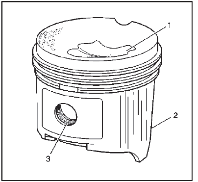
3. Inspect the pistons for the following conditions:
- Cracked ring lands, skirts, or pin bosses
- Ring grooves for nicks, burrs that may cause binding
- Warped or worn ring lands
- Eroded areas at the top of the piston (1)
- Scuffed or damaged skirts (2)
- Worn piston pin bores (3)
4. Replace pistons that show any signs or damage or excessive wear.
5. Measure the piston pin bore to piston pin clearances using the following procedure:
- Piston pin bores and pins must be free of varnish or scuffing.
- Use an outside micrometer to measure the piston pin in the piston contact areas.
- Using an inside micrometer, measure the piston pin bore.
- Subtract the measurement of the piston pin bore from the piston pin. The clearance should be within 0.002 - 0.012 mm (0.00007 - 0.00047 in).
- If the clearance is excessive, determine which component is out of specification.
6.
.png)
Measure the piston ring end gap using the following procedure:
- Place the piston ring in the area of the bore where the piston ring will travel (approximately 25 mm or 1 inch down from the deck surface). Be sure the ring is square with the cylinder bore by positioning the ring with the piston head.
- Measure the end gap of the piston ring with feeler gauges (1). Compare
the measurements with those
provided below:
- The top compression ring end gap should be 0.20 - 0.40 mm (0.0060 - 0.015 in).
- The second compression ring end gap should be 0.35 - 0.55 mm (0.0137 - 0.0216 in).
- The oil ring end gap should be 0.25 - 0.76 mm (0.0098 - 0.029 in).
- If the clearance exceeds the provided specifications, the piston rings must be replaced.
- Repeat the procedure for all the piston rings.
7.
.png)
Measure the piston ring side clearance using the following procedure:
- Roll the piston ring entirely around the piston ring groove. If any binding is caused by a distorted piston ring, replace the ring.
- With the piston ring on the piston, use feeler gauges (1) to check clearance at multiple locations.
- The clearance between the surface of the top piston ring and the ring land should be no greater than 0.075 mm (0.0030 in).
- If the clearance is greater than specifications, replace the piston ring.
- If the new ring does not reduce the top ring side clearance to 0.075 mm (0.0030 in) or less, install a new piston.
8. The top compression ring may be installed with either side up. There is a locating dimple on the 2nd compression ring near the end for identification of the top side. Install the 2nd compression ring with the dimple facing up.
9. The clearance between the surface of the second piston ring and the ring land should be no greater than 0.069 mm (0.0026 in).
10. If the new ring does not reduce the clearance to 0.069 mm (0.0026 in) or less, install a new piston.
11.
.png)
Measure piston width using the following procedure:
- Using an outside micrometer (2), measure the width of the piston 14.5 mm (0.570 in) above the bottom of the piston skirt at the thrust surface perpendicular to the centerline of the piston pin.
- Compare the measurement of the piston to its original cylinder by subtracting the piston width from the cylinder diameter.
- The proper clearance specification for the piston is 0.010 - 0.041 mm (0.0004 - 0.0016 in).
12. If the clearance obtained through measurement is greater than these specifications and the cylinder bores are within specification, replace the piston (1).
Piston Selection
1.
.png)
NOTE: Measurements of all components should be taken with the components at normal room temperature.
For proper piston fit, the engine block cylinder bores must not have excessive wear or taper.
A used piston and pin set may be reinstalled if, after cleaning and inspection, they are within specifications.
Inspect the engine block cylinder bore. Refer to Engine Block Cleaning and Inspection.
2. Inspect the piston and the piston pin.
3. Use a bore gauge (1) and measure the cylinder bore diameter. Measure at a point 64 mm (2.5 in) from the top of the cylinder bore.
4.
.png)
Measure the bore gauge with a micrometer (1) and record the reading.
5.
.png)
With a micrometer (2) or caliper at a right angle to the piston (1), measure the piston 14 mm (0.570 in) from the bottom of the skirt.
6. Subtract the piston diameter from the cylinder bore diameter in order to determine piston-to-bore clearance.
7. For proper piston-to-bore clearance. Refer to Engine Mechanical Specifications.
8. If the proper clearance cannot be obtained, select another piston and measure for the clearances.
9. If the proper fit cannot be obtained, hone the cylinder bore or replace the cylinder block.
10. When the piston-to-cylinder bore clearance is within specifications, mark the top of the piston using a permanent marker for installation to the proper cylinder. Refer to Separating Parts.
Piston and Connecting Rod Assemble
Special Tools
- EN-46745 Piston Pin Clip Remover/Installer
- EN-46745-4 Piston Pin Clip Remover/Installer Adapter
For equivalent regional tools, refer to Special Tools.
1.
.png)
NOTE: Install the piston onto the connecting rod with the arrow on top of the piston oriented to the same side as the cast feature at the split line of the connecting rod.
The arrow (1), on the top of the piston, must go to the front of the block.
2. The feature at the split line (4), located on one side of the connecting rod, must go to the front of the block.
3. Assemble the connecting rod (3) and the piston (2).
4.
.png)
CAUTION: Install the piston pin retainers correctly in the retaining groove during assembly in order to avoid engine damage.
NOTE: Use NEW retainers. Two retainers hold each piston pin in place.
NOTE: Use the appropriate adapter for EN-46745 installer to install the retainers. The appropriate adapter will fit the piston pin ID and allow the ring to be removed or installed.
- For LCV/LKW/LD4 piston pin, use EN-46745-2 adapter.
- For LTG piston pin, use EN-46745-4 adapter.
Use the following procedure to assemble the piston pin and the retainer:
- Coat the piston pin with oil.
- Install one NEW piston pin retainer into the retaining groove using EN-46745 installer and the appropriate adapter. Rotate the retainer until it is fully seated in the groove.
- Install the connecting rod and the piston pin.
Push the piston pin until it bottoms in the previously installed retainer.
- Install the second NEW piston pin retainer, using EN-46745 installer (1) and the appropriate adapter.
- Ensure that the piston moves freely.
5.
.png)
The piston ring end gaps must be positioned 90 degrees to each other.
- Upper compression ring joint (1)
- Lower compression ring joint (2)
- Upper oil ring rail joint (5)
- Oil ring rail spacer joint (4)
- Lower oil ring rail joint (3)
6.
.png)
CAUTION: Use a piston ring expander to install the piston rings. The rings may be damaged if expanded more than necessary.
Install the following components of the oil control ring assembly:
- The piston oil ring rail (5)
- The piston oil ring rail spacer (4)
- The second piston oil ring rail (3)
7. Install the piston lower compression ring (2). Place the manufacturer's mark facing up.
8. Install the piston upper compression ring (1).
CAMSHAFT ASSEMBLY DISASSEMBLE
.png)
Preliminary Procedures
1. Temporarily install the cylinder head to the engine block, with the engine block securely attached to a mounting device.
2. Temporarily install the engine front cover to the cylinder head, using the upper bolts to hold the cover in position.
3. Install one of the camshafts in the exhaust camshaft position on the cylinder head.
4. Install the camshaft bearing front upper cap and bolts.
5. Install the camshaft bearing caps and bolts.
6. Install EN-50793 locking tool onto the camshaft actuator and engine front cover.
7. The camshaft actuator bolt can now be loosened and the actuator removed from the camshaft. Repeat preliminary procedure for the remaining camshaft assembly.
- Camshaft, Intake and Exhaust
- Camshaft Position Actuator Bolt
NOTE: Discard the bolt.
Special Tools
EN-50793 Camshaft Actuator Locking Tool
For equivalent regional tools, refer to Special Tools. - Camshaft Position Actuator, Intake and Exhaust
CAMSHAFT CLEANING AND INSPECTION
1.
.png)
Inspect the camshaft journals and lobes for wear or scoring.
2. Inspect the camshaft sprocket alignment notch for damage.
3. Wash the camshafts (1, 2) in solvent.
4. Oil the camshafts.
CAMSHAFT ASSEMBLY ASSEMBLE
.png)
Preliminary Procedures
1. Temporarily install the cylinder head to the engine block, with the engine block securely attached to a mounting device.
2. Temporarily install the engine front cover to the cylinder head, using the upper bolts to hold the cover in position.
3. Install one of the camshafts in the exhaust camshaft position on the cylinder head.
4. Install the camshaft bearing front upper cap and bolts.
5. Install the camshaft bearing caps and bolts.
6. Install the appropriate actuator for the camshaft currently installed on the cylinder head.
7. Install EN-50793 locking tool onto the camshaft actuator and engine front cover.
8. The camshaft actuator bolt can now be installed and tightened to final specification. Repeat preliminary procedure for the remaining camshaft assembly.
- Camshaft, Intake and Exhaust
NOTE: Ensure that the oil seal near the front of the camshaft is rotated so that the split line on the oil seal is aligned with the notch, and both the notch and split line are at 12 O'clock when installed on the cylinder head. - Camshaft Position Actuator, Intake and Exhaust
NOTE: Upon camshaft assembly, ensure the camshaft actuator pin aligns with the camshaft notch. The actuator, camshaft, and bolt can be assembled by hand and then placed on the cylinder head for final torque.
NOTE: Lubricate the actuator prior to installation. - Camshaft Position Actuator Bolt
CAUTION: Refer to Fastener Caution.
CAUTION: This vehicle is equipped with torque-to-yield or single use fasteners. Install a NEW torque-to-yield or single use fastener when installing this component. Failure to replace the torque-to-yield or single use fastener could cause damage to the vehicle or component.
Tighten 30 N.m (22 lb ft) plus 100 Degrees.
Special Tools
EN-50793 Camshaft Actuator Locking Tool
For equivalent regional tools, refer to Special Tools.
CAMSHAFT TIMING CHAIN, SPROCKET, AND TENSIONER CLEANING AND INSPECTION
1.
.png)
Inspect the timing chain guides (3, 7) and timing chain tensioner pivot arm (1) for cracking or wear.
2. Replace the timing chain guides if wear exceeds 1.12 mm (0.045 in) depth on the chain guide surface.
3. Inspect the timing chain tensioner (13) shoe for wear.
4. Replace the timing chain tensioner if shoe wear exceeds 1.12 mm (0.045 in) depth on the chain guide surface.
5. Inspect the timing chain (4) and actuators (2, 5) for wear.
6. Inspect the camshaft actuator faces for signs of movement.
7. Inspect the camshaft actuator teeth and chain for signs of excessive wear, chipping, or seizure of the timing chain links.
8. Inspect the timing chain oil nozzle (6) for collapse or cracks at the bolt boss. Discard and replace the oil nozzle body if it is damaged.
9. Verify oil nozzle oil flow with compressed air.
10. Inspect the timing chain tensioner (13) for scoring or free movement.
11. Inspect the timing chain tensioner washer. If damaged, replace the timing chain tensioner.
12. Inspect the crankshaft sprocket (12) for excessive wear or chipping.
13. Inspect the balancer chain (8) for wear.
14. Inspect the balancer chain guide (11) for wear.
15. Inspect the balancer chain tensioner (9) for wear.
16. Inspect the balancer shaft driven sprocket (10) for wear or chipping.
Cylinder Head Disassemble
Special Tools
- EN-43963 Valve Spring Compressor (off car)
- EN-46116 Valve Stem Seal Remover/Installer
- EN-50717 Valve Spring Compressor
For equivalent regional tools, refer to Special Tools.
1.
.png)
Remove the intake camshaft position sensor (2) and bolt (1).
2.
.png)
Remove the exhaust camshaft position sensor (2) and bolt (1).
3.
.png)
WARNING: Compressed valve springs have high tension against the valve spring compressor. Valve springs that are not properly compressed by or released from the valve spring compressor can be ejected from the valve spring compressor with intense force. Use care when compressing or releasing the valve spring with the valve spring compressor and when removing or installing the valve stem keys. Failing to use care may cause personal injury.
CAUTION: Do not compress the valve springs to less than 24.0 mm (0.943 in). Contact between the valve spring retainer and the valve stem oil seal can cause potential valve stem oil seal damage.
NOTE: Ensure that the valve train components are kept together and identified in order for proper installation in their original position.
Perform the following procedure to remove the valve keys, springs, and retainers:
- Using the EN-50717 fixture and the EN-43963 compressor adapter, compress the valve spring.
- Remove the valve keys (1).
- Slowly release the compression from the valve spring assembly.
- Remove the retainer (2).
4.
.png)
Remove the springs (1).
5.
.png)
CAUTION: Do not damage the valve guide. Remove any burrs that have formed at the key groove by chamfering the valve stem with an oil stone or a file.
Using EN-46116 remover, remove the valve seals (1). Discard the seals, do not reuse.
6.
.png)
Remove the valves (1, 2).
7.
.png)
Remove the cylinder head plug (1).
8.
.png)
Remove the cylinder head plugs (1).
CYLINDER HEAD CLEANING AND INSPECTION
Special Tools
- EN 22738-B Valve Spring Tester
- EN-28410 Gasket Remover
- EN-39358 Spark Plug Socket
- GE 7872 Magnetic Base Dial Indicator
For equivalent regional tools, refer to Special Tools.
Valve Cleaning and Inspection
1.
.png)
NOTE: Do not use a wire brush on any part of the valve stem.
NOTE: Do not grind or condition the intake valve. If the intake valve is out of specification, replace the valve.
Clean the valves of carbon, oil and varnish. Use a soft bristle wire brush to clean any carbon build-up from the valve head. Varnish can be removed by soaking in Parts Immersion Solvent.
2. Clean the valve guides.
3. Inspect the valve stem for pitting or wear (4).
4. Inspect the valve key groove for chipping or wear (5). Replace the valve if chipped or worn.
5. Inspect the valve face for burning or cracking (1). If pieces are broken off, inspect the corresponding piston and cylinder head area for damage.
6. Inspect the valve stem for burrs and scratches. Burrs and minor scratches may be removed with an oil stone.
7. Inspect the valve stem for straightness (3) and the valve head for bending or distortion using V blocks. Bent or distorted valves must be replaced.
8. Clean the deposits from the valve face. Inspect the valve face for grooving.
9. Replace the valve if the face is grooved. Valve faces cannot be machined. If worn, or damaged, the valves must be replaced.
10. Replace the valve if the valve head O.D. and chamfer (2) is worn or out of specification. Refer to Valve and Seat Grinding.
11. The valves may be lightly lapped to the valve seats.
12. Replace the valve if the valve tip (6) is worn.
13. If no apparent wear, pitting, grooving, or distortion is present, perform the valve measurement and reconditioning procedure to verify valve specification. Refer to Valve and Seat Grinding.
Valve Guide Measurement
1.
.png)
Measure the valve stem (1)-to-guide (2) clearance. Excessive valve stem-to-guide clearance may cause an excessive oil consumption and may also cause a valve to break. Insufficient clearance will result in noisy and sticky functioning of the valve and will disturb the engine assembly smoothness.
2. Clamp the GE 7872 dial indicator to the cylinder head at the camshaft cover rail.
3. Locate the dial indicator so that the movement of the valve stem from side to side, crossways to the cylinder head, will cause a direct movement of the indicator stem. The dial indicator stem must contact the side of the valve stem just above the valve guide.
4. Drop the valve head about 0.064 mm (0.0025 in) off the valve seat.
5. Use light pressure when moving the valve stem from side to side in order to obtain a clearance reading. Refer to Engine Mechanical Specifications for proper clearance.
NOTE: Valve guide wear at the bottom 10 mm (0.390 in) of the valve guide is not significant to normal operation.
6. If the clearance for the valve is greater than specifications and a new standard diameter valve stem will not bring the clearance within specifications, replace the cylinder head.
Valve Spring Cleaning and Inspection
1. Clean the valve springs in solvent.
WARNING: Refer to Safety Glasses Warning.
2. Dry the valve springs with compressed air.
3. Inspect the valve springs for broken coils or coil ends.
4.
.png)
Measure the valve spring tension using the EN 22738-B tester. Refer to Engine Mechanical Specifications 5. If low valve spring load is found, replace the valve springs. DO NOT use shims to increase spring load. The use of shims can cause the valve spring to bottom out before the camshaft lobe is at peak lift.
Valve Rocker Arm Cleaning and Inspection
1.
.png)
Inspect the camshaft follower roller (1) for the following:
- Flat spots
- Excessive scoring and pitting
- Ensure the roller spins freely
2. Inspect the camshaft follower valve tip area (2).
3. Inspect the camshaft follower stationary hydraulic lash adjuster (SHLA) pivot area (3).
4. Replace the camshaft follower or followers as necessary.
Cylinder Head and Gasket Surface Cleaning and Inspection
1.
.png)
Remove the spark plugs (1) using EN-39358 socket.
2. Inspect the cylinder head gasket and mating surfaces for leaks, corrosion and blow-by. If the gasket has failed, use the following faults to determine the cause:
- Improper installation
- Loose or warped cylinder head
- Missing, off location or not fully seated dowel pins
- Corrosion in the seal area around the coolant passages
- Chips or debris in the cylinder head bolt holes
- Bolt holes in the cylinder block not drilled or tapped deep enough
3.
.png)
Inspect the cylinder head gasket surface.
- Cylinder head may be reused if corrosion is found only outside a 4 mm (0.375 in) band around each combustion chamber (1).
- Replace the cylinder head if the area between the valve seats is cracked (2).
- Replace the cylinder head if corrosion has been found inside a 4 mm (0.375 in) band around each combustion chamber (3).
4. Ensure proper use of room temperature vulcanizing (RTV) sealant.
NOTE: Do not use a wire brush on any gasket sealing surface.
5. Remove the sealant from the rear cap mating surface with EN-28410 remover. Care must be used to avoid gouging or scraping the sealing surfaces.
6. Clean the cylinder head. Remove all varnish, soot and carbon to the bare metal.
7. Clean the valve guides.
8. Clean the threaded holes. Use a nylon bristle brush.
9. Clean the remains of the sealer from the plug holes.
10. Inspect the cylinder head for cracks. Check between the valve seats and in the exhaust ports.
NOTE: Do not attempt to weld the cylinder head, replace it.
11. Inspect the cylinder head deck for corrosion, sand inclusions and blow holes.
12.
.png)
Using a straight edge (1) and feeler gauge (2), inspect the cylinder head deck surface for flatness. Refer to Engine Mechanical Specifications. If the cylinder head is out of specification, replace the cylinder head. Do not machine the cylinder head.
13. Inspect all the threaded holes for damage. Threads may be reconditioned with thread inserts.
14. Inspect the sealing surfaces.
15.
.png)
Inspect the intake camshaft bearing rear cap (2) for damage.
16. Inspect the camshaft bearing caps (1) for damage.
17. Inspect the camshaft front upper and lower bearing caps (3, 4) for damage.
18.
.png)
CAUTION: Refer to Component Fastener Tightening Caution.
Install the spark plugs (1) using EN-39358 socket. Tighten the plugs to 20 N.m (15 lb ft).
Valve and Seat Grinding
Valve Measurement and Reconditioning Overview
- Proper valve service is critical to engine performance. Therefore, all detailed measurement procedures must be followed to identify components that are out of specification.
- If the measurement procedures reveal that the valve or valve seat must be reconditioned, it is critical to perform the measurement procedures after reconditioning.
Valve Seat Width Measurement Procedure
1.
.png)
Measure the valve seat width in the cylinder head using a proper scale.
2.
.png)
Measure the seat width (b) on the valve face (1) using a proper scale.
NOTE: The seat contact area must be at least 0.5 mm (0.020 in) from the outer diameter, margin (a), of the valve. If the contact area is too close to the margins, the seat must be reconditioned to move the contact area away from the margin.
3. Compare your measurements with the specifications listed in Engine Mechanical Specifications.
4. If the seat widths are acceptable, check the valve seat roundness using the Valve Seat Roundness Measurement Procedure.
5. If the seat width is not acceptable, you must grind the valve seat using the Valve and Seat Reconditioning Procedure to bring the width back into specification. Proper valve seat width is critical to providing the correct amount of valve heat dissipation.
Valve Seat Roundness Measurement Procedure
1. Measure the valve seat roundness using a dial indicator attached to a tapered pilot installed in the guide. The pilot should have a slight bind when installed in the guide.
CAUTION: The correct size pilot must be used. Do not use adjustable diameter pilots.
Adjustable pilots may damage the valve guides.
2. Compare your measurements with the specifications listed in Engine Mechanical Specifications.
3. If the valve seat exceeds the roundness specification, you must grind the valve and valve seat using the Valve and Seat Reconditioning Procedure.
4. If new valves are being used, the valve seat roundness must be within 0.05 mm (0.002 in).
Valve Head O.D. and Chamfer Measurement Procedure
1.
.png)
Measure the valve head O.D. and chamfer (a) using an appropriate scale. Refer to Engine Mechanical Specifications.
2. If the valve head O.D. and chamfer is within specification, test the valve (1) for seat concentricity using the Valve-to-Seat Concentricity Measurement Procedure. Reinspect the valve head O.D. and chamfer after completing the concentricity measurement if valve seat reconditioning is performed.
Valve-to-Seat Concentricity Measurement Procedure
NOTE: Checking the valve-to-seat concentricity determines whether the valve and seat are sealing properly.
You must measure the valve face and the valve seat to ensure proper valve sealing.
1.
.png)
Coat the valve face (3) lightly with blue dye (1).
2. Install the valve in the cylinder head.
3. Turn the valve against the seat with enough pressure to wear off the dye.
4. Remove the valve from the cylinder head.
5. Inspect the valve face.
- If the valve face is concentric, providing a proper seal, with the valve stem, a continuous mark (2) will be made around the entire face.
NOTE: The wear mark MUST be at least 0.5 mm (0.020 in) from the outer diameter, the margin (a), of the valve. If the wear mark is too close to the margin, the seat must be reconditioned to move the contact area away from the margin.
NOTE: Do not grind or condition the intake valve. If the intake valve is out of specification, replace the valve.
- If the face is not concentric with the stem, the mark will NOT be continuous around the valve face. The valve should be refaced or replaced and the seat must be reconditioned using the Valve and Seat Reconditioning Procedure.
Valve and Seat Reconditioning Procedure
1.
.png)
NOTE:
- If the valve seat width, roundness or concentricity is beyond specifications, you must grind the seats in order to ensure proper heat dissipation and prevent the build up of carbon on the seats.
- It is necessary to reface the valve if seat reconditioning is required unless a new valve is used.
Grind the valve seating surface (a) to the proper angle specification (2) listed in Engine Mechanical Specifications.
2. Grind the valve relief surface to the proper angle specification (1) listed in Engine Mechanical Specifications, to correctly position the valve seating surface (a) to the valve.
3. Grind the valve undercut surface to the proper angle specification (3) listed in Engine Mechanical Specifications, to narrow the valve seating surface width (a) to the specifications listed in Engine Mechanical Specifications.
NOTE: Do not grind or condition the intake valve. If the intake valve seat has been reconditioned, replace the corresponding intake valve.
4. Replace the intake valve if it is out of specification. Refer to Engine Mechanical Specifications.
5. If the original exhaust valve is being used, grind the valve to the specifications listed in Engine Mechanical Specifications. Measure the valve head O.D. and chamfer again after grinding using the Valve Head O.D. and Chamfer Measurement Procedure. Replace the exhaust valve if it is out of specification. New valves do not require grinding.
6. When grinding the valves and seats, grind off as little material as possible. Cutting valve seat results in lowering the valve spring pressure.
7. Install the valve in the cylinder head.
- If you are using refaced exhaust valves, lap the valves into the seats with a fine grinding compound. The refacing and reseating operations should leave the refinished surfaces smooth and true so that minimal lapping is required. Excessive lapping will groove the valve face and prevent a good seat when hot.
- Be sure to clean any remaining lapping compound from the valve and seat with solvent and compressed air prior to final assembly.
8. After obtaining the proper valve seat width in the cylinder head, you must re-measure the valve stem height using the Valve Stem Height Measurement Procedure.
9. If the valve stem height is acceptable, test the seats for concentricity using the Valve-to-Seat Concentricity Measurement Procedure.
Valve Stem Height Measurement Procedure
1.
.png)
NOTE: To determine the valve stem height measurement, measure from the valve spring seat to the valve spring retainer.
Install the valve (1) into the valve guide in the cylinder head (2).
2. Ensure the valve is seated to the cylinder head valve seat.
3. Install the valve stem oil seal.
4. Install the valve spring retainer and valve stem locks.
5. Measure the distance (a) between the valve seal lip to the bottom of the valve spring retainer. Refer to Engine Mechanical Specifications.
6. If the maximum height specification is exceeded, a new valve should be installed and the valve stem height remeasured.
CAUTION: DO NOT grind the valve stem tip. The tip of the valve is hardened and grinding the tip will eliminate the hardened surface causing premature wear and possible engine damage.
CAUTION: DO NOT use shims in order to adjust valve stem height. The use of shims will cause the valve spring to bottom out before the camshaft lobe is at peak lift and engine damage could result.
7. If the valve stem height still exceeds the maximum height specification, the cylinder head must be replaced.
Cylinder Head Assemble
Special Tools
- EN-50717 Valve Spring Compressor
- EN-9666 Valve Spring Tester
- EN-43963 Valve Spring Compressor (off car)
For equivalent regional tools, refer to Special Tools.
1.
.png)
CAUTION: Refer to Component Fastener Tightening Caution.
CAUTION: In order to avoid damage, install the spark plugs after the cylinder head has been installed on the engine.
Install NEW cylinder head plugs. Coat the plugs with sealer. Refer to Adhesives, Fluids, Lubricants, and Sealers.
2. Install the water jacket hole plugs (1) in the top of the cylinder head. Tighten the plugs to 50 N.m (37 lb ft).
3.
.png)
Install the oil gallery plug (1) in the rear of the cylinder head. Tighten the plug to 40 N.m (30 lb ft).
4. Inspect the valve springs for the following conditions:
- Expanded height
- Unparallel spring ends
- Spring tension using EN-9666 tester
- Any distorted springs should be replaced
5.
.png)
Inspect the valves and the valve seats. Refer to Valve and Seat Grinding.
6. Lubricate the valves. Refer to Adhesives, Fluids, Lubricants, and Sealers.
7. Install the valves (1, 2). Replace the valves, if required.
8.
.png)
NOTE: Always use NEW valve stem oil seals when assembling the cylinder head.
Install the NEW valve seals (1). Fully seat the seals on the valve guides.
9.
.png)
Install the springs (1).
10.
.png)
WARNING: Compressed valve springs have high tension against the valve spring compressor. Valve springs that are not properly compressed by or released from the valve spring compressor can be ejected from the valve spring compressor with intense force. Use care when compressing or releasing the valve spring with the valve spring compressor and when removing or installing the valve stem keys. Failing to use care may cause personal injury.
CAUTION: Do not compress the valve springs to less than 24.0 mm (0.943 in). Contact between the valve spring retainer and the valve stem oil seal can cause potential valve stem oil seal damage.
Install the retainers and keys using the following procedure:
- Install the retainer (2).
- Using the EN-50717 compressor and the EN-43963 adapter, compress the valve spring.
- Install the valve keys (1).
- Slowly release the compression from the valve/spring assembly.
- Inspect for proper valve key seating.
11.
.png)
Lubricate the camshaft position sensor O-ring with clean engine oil.
CAUTION: Refer to Fastener Caution.
12. Install the exhaust camshaft position sensor (2) and bolt (1). Tighten the bolt to 10 N.m (89 lb in).
13.
.png)
Lubricate the camshaft position sensor O-ring with clean engine oil.
14. Install the intake camshaft position sensor (2) and bolt (1). Tighten the bolt to 10 N.m (89 lb in).
BALANCER SHAFT WITH OIL PUMP DISASSEMBLE
.png)
- Oil Pump Suction Pipe Bolt
- Oil Pump Screen Assembly with Suction Pipe
- Oil Pump Screen Gasket
NOTE: Discard the gasket. - Oil Pump Assembly Bolt
- Oil Pump Assembly
- Oil Pump Cover
- Oil Pump Locating Pin
- Balancer Shaft Module
BALANCER SHAFT WITH OIL PUMP CLEANING AND INSPECTION
.png)
Preliminary Procedures
1. Completely inspect the balancer with oil pump shaft assembly and components.
2. Clean all mating surfaces.
3. Inspect all threaded holes for damage.
4. Inspect the oil pump screen assembly.
- Oil Pump Assembly
- Oil Pump Cover
- Balancer Shaft Module
- Oil Pump Locating Pin
- Oil Pump Screen Assembly with Suction Pipe
BALANCER SHAFT WITH OIL PUMP ASSEMBLE
.png)
- Balancer Shaft Module
- Oil Pump Locating Pin
- Oil Pump Cover
- Oil Pump Assembly
- Oil Pump Assembly Bolt
CAUTION: Refer to Fastener Caution.
Tighten 10 N.m (89 lb in) - Oil Pump Screen Gasket
NOTE: Use NEW gasket. - Oil Pump Screen Assembly with Suction Pipe
- Oil Pump Suction Pipe Bolt
Tighten 10 N.m (89 lb in)
CAMSHAFT COVER AND COMPRESSOR AIR INTAKE TURBOCHARGER CLEANING AND INSPECTION
Positive Crankcase Ventilation System Overview
.png)
Preliminary Procedure
The tamper-proof positive crankcase ventilation system includes components that may be replaced if necessary. The system may include an outlet duct connected to the end of the Positive Crankcase Ventilation Tube. If any component is suspect, refer to the inspection procedures and individual replacement procedures before attempting to disassemble the PCV system. Be careful when moving the assembled components with tamper-proof fittings to avoid stress on the connections.
- Camshaft Cover
NOTE: In the event that the camshaft cover requires replacing, the PCV hose at the air outlet duct and turbocharger will be removed by cutting and/or prying at the connection. The air outlet duct and turbocharger must remain intact in order to reinstall these components.
Procedure- Thoroughly clean the camshaft cover and mating surfaces. Inspect each component, Orings, and fasteners, and replace as necessary.
- Ensure proper use of room temperature vulcanizing (RTV) sealant. Use of Room Temperature Vulcanizing (RTV) and Anaerobic Sealant
- Refer to Camshaft Cover Replacement if the camshaft cover does not pass inspection.
- Positive Crankcase Ventilation Tube
NOTE: All PCV valves are tamper-proof and cannot be serviced.
Procedure
Inspect the PCV connection fittings and tubes. Replace the Positive Crankcase Ventilation Tube if suspect.
NOTE: The PCV fitting is tamper-proof and cannot be serviced. A new PCV tube and valve are included with a new turbocharger assembly.
NOTE: On earlier designs of this system the fastener at the PCV fitting on the turbocharger was not tamper-proof. To aid in disassembly or removal, this fastener can be removed if it is not tamper-proof.
Procedure
Completely inspect the turbocharger and all other engine components that may cause similar conditions before replacing the turbocharger. - Positive Crankcase Ventilation Tube
NOTE: All PCV valves and fittings are tamper-proof and cannot be serviced.
Procedure
Inspect the PCV connection fittings and tubes. Replace the Positive Crankcase Ventilation Tube if suspect.
NOTE: The air cleaner outlet duct is equipped with a tamper proof connection that should NOT be removed unless the PCV tube or air cleaner outlet duct is being replaced. Loosening the air cleaner outlet duct clamps will allow the duct to be disconnected from the air cleaner assembly and turbocharger for repositioning without removing the tamper proof connection.
Procedure
Inspect the duct and hose, or the connection if the duct is not attached to the hose. Replace any components that are suspect.
Camshaft Cover - Top
.png)
Preliminary Procedure
1. Thoroughly clean the camshaft cover and mating surfaces. Inspect each component, O-rings, and fasteners, and replace as necessary.
2. Ensure proper use of room temperature vulcanizing (RTV) sealant.
- Engine Coolant Air Bleed Hose
- Engine Coolant Air Bleed Pipe
- Engine Coolant Air Bleed Pipe O-Ring
- Camshaft Cover
- Camshaft Position Actuator Solenoid Valve - Intake
- Camshaft Cover Plug
CAUTION: Refer to Fastener Caution.
Tighten 35 N.m (26 lb ft) - Vacuum Pump Seal
Special Tools
DT 45866 Input Shaft Seal Installer
Equivalent regional tools: Special Tools. - Ignition Coil
- Camshaft Position Actuator Solenoid Valve - Exhaust
Camshaft Cover - Bottom
.png)
Preliminary Procedure
Inspect each component, O-rings, and fasteners, and replace as necessary.
- Camshaft Cover Locating Pin [2x]
- Positive Crankcase Ventilation Valve
- Spark Plug Shield Seal
Special Tools
EN 34115 Sprocket Bearing Installer
Equivalent regional tools: Special Tools.
Turbocharger and Components Cleaning and Inspection
.png)
- Turbocharger
Procedure- Clean all mating surfaces.
- Inspect all threaded holes for
damage.
NOTE: PCV fluids and combustion product buildup are common and not a sign of failure. - Inspect the compressor and turbine
blades for bent or broken conditions, and foreign material.
NOTE: Do not replace the turbocharger if cracks are found on the turbocharger inlet flange partition wall. Replacement should only be performed if external leaks are present or a section is loose or missing. - Inspect the turbocharger compressor
inlet, compressor outlet, turbine inlet, and turbine outlet surfaces for
damage. Replace the turbocharger if damage is found.
NOTE: A new PCV tube and fitting are included with a new turbocharger assembly. - Replace the turbocharger if damage is found.
- Turbocharger Bypass Valve Solenoid
Procedure
Inspect the bypass valve solenoid for damage. Replace if necessary. - Turbocharger Wastegate Regulator
Solenoid Valve
NOTE: Do not disassemble solenoid valve from bracket.
Procedure
Inspect the solenoid valve and bracket for damage. Replace if necessary. - Turbocharger Wastegate Regulator
Solenoid Valve Hose [3x]
Procedure
Inspect the turbocharger wastegate regulator solenoid hoses for damage. Replace the hoses if necessary. - Turbocharger Wastegate Actuator
Procedure- Inspect the turbocharger wastegate actuator.
- Inspect the wastegate actuator rod for damage or tampering.
- Replace the wastegate actuator if damage is found.
- Turbocharger Oil Feed Pipe
Procedure
Inspect the pipe. Replace if necessary. - Turbocharger Coolant Return Pipe
Procedure
Inspect the pipe. Replace if necessary. - Turbocharger Coolant Feed Pipe
Procedure
Inspect the pipe. Replace if necessary. - Turbocharger Oil Return Pipe
Procedure
Inspect the pipe. Replace if necessary.
Fuel Rail and Injectors Cleaning and Inspection
Special Tools
- EN-47909 Injector Bore and Sleeve Cleaning Kit
- EN-49245 Fuel Injector Seal Install/Sizer
- EN-50791 Fuel Injector Nozzle Installer
- EN-51105 Fuel Injector Seal Installer
For equivalent regional tools, refer to Special Tools.
1.
.png)
Remove and inspect the fuel rail insulator assemblies (1 - 4). Replace the entire assembly if any components show signs of wear or the insulators (4) show the following conditions:
- Dry or cracked appearance
- Flattened or misshapen appearance
2.
.png)
Disconnect the electrical connections from the fuel injectors.
3. Use EN-50791 installer (3) to compress the fuel injector (1), and relieve pressure on the retaining pin (2).
Remove the fuel injector retaining pin (2). Remove EN-50791 installer once the retaining pin is removed.
4.
.png)
NOTE:
- Support the fuel injector at the widest point. Support the fuel rail along the bottom.
- DO NOT support or hold the fuel injector by the tip or connector
- DO NOT tilt or excessively twist the injector during removal
Remove the injectors (1) from the fuel rail by pulling straight out along the fuel injector axis. Slight rotation of the fuel injector is acceptable as long as excessive force is not applied to the fuel injector tab while engaged in the fuel rail slot (3).
5. Remove the fuel injector holding clamp (2) from the rear of the fuel injector.
6.
.png)
Remove and discard the fuel injector O-ring (2) and plastic spacer (1).
7. Remove and discard the fuel injector seals (3).
8.
.png)
NOTE: Do not soak or submerge the fuel rail or injectors in solvent. Do not use solvent on the fuel rail label.
Clean the exterior of the fuel rail (1) and injectors in solvent.
9. Using EN-47909 cleaning kit, clean the fuel injector bores and sleeves.
10. Inspect the fuel rail and components for the following conditions:
- Damage, debris, or restrictions to the fuel rail
- Damage, debris, or restrictions to the fuel ports in the fuel rail
- Damage to the mounting area for the fuel rail
- Damage to the fuel rail mounting bolts
- Damage to the threads on the fuel rail fuel feed fitting
11. Replace the fuel rail if any damage is found. Do not attempt to repair a fuel rail.
CAUTION: Refer to Fastener Caution.
NOTE: Remove and inspect the fuel pressure sensor only if the sensor is suspect.
12. Inspect the fuel pressure sensor (3) for damage.
- Disconnect the harness connector (2) from the fuel pressure sensor.
- Remove the fuel pressure sensor. Dry the fuel pressure sensor bore in
the fuel rail with a lint free cloth.
The bore should be free of fuel, debris, and burrs.
- Lubricate the fuel rail fuel pressure sensor bore with clean engine oil.
- Lubricate the threads and sealing area on the fuel pressure sensor with clean engine oil.
- Install the fuel pressure sensor hand tight.
- Remove the fuel pressure sensor and re-lubricate the bore, threads, and sealing area.
- Install the fuel pressure sensor and tighten to 33 N.m (25 lb ft).
- Connect the harness connector to the fuel pressure sensor.
13.
.png)
Inspect the fuel injectors for the following conditions:
- Damage to the fuel injector connector (3)
- Damage to the fuel injector harness connector
- Damage to the fuel injector tip (5)
- Damage to the fuel injector (4)
14. Replace the fuel injector if any damage is found. Do not attempt to repair a fuel injector.
15. Install the a new fuel injector spacer (1).
16. Lubricate the NEW O-ring (2) with one drop of clean engine oil.
17. Install the O-ring on the injector.
18.
.png)
Install the fuel injector holding clamp (2) onto the rear of the fuel injector.
19. Hand install fuel injectors (1) to the fuel rail, carefully aligning the fuel injector tab to the slot in the fuel rail (3).
20.
.png)
NOTE: The injector must be fully installed and properly aligned with the fuel rail before installing the retaining pin.
Using EN-50791 installer (3), compress the fuel injector (1) into the fuel rail.
21. Ensure the fuel injector is fully seated in the fuel rail, and install the fuel injector retaining pin (4).
22. Ensure the fuel injector retaining pin is fully seated in the fuel rail. Remove EN-50791 installer. Repeat process until all fuel injectors are properly installed to the fuel rail.
23.
.png)
Connect the electrical connection to the fuel rail.
24. Connect the fuel rail harness connectors (1) to the fuel injectors.
25.
.png)
NOTE: Do not use any type of lubricant when installing the NEW seals on the fuel injector tip.
Install EN-51105-1 long protector (2) onto the fuel injector tip. Place a NEW seal (1) on EN-51105-1 long protector.
26. Using EN-49245 pusher, install the seal into the second recessed area (3) of the fuel injector, then remove the EN-51105-1 long protector.
27. Compress the seal with your fingers, then resize the seal using the EN-49245 sizer (4).
28. Install EN-51105-2 short protector (2) onto the fuel injector tip. Place a second NEW seal (1) on EN-51105-2 short protector.
29. Using EN-49245 pusher, install the seal into the remaining recessed area of the fuel injector, then remove EN- 51105-2 short protector.
30. Compress the seal with your fingers, then resize the seal using the EN-49245 sizer (4).
INTAKE MANIFOLD CLEANING AND INSPECTION
1.
.png)
Clean the intake manifold (1) mating surfaces.
2. Inspect the intake manifold for damage.
3. Inspect the intake manifold for cracks near metallic inserts.
4.
.png)
Inspect the crankcase ventilation passages (1) in the intake manifold face for blockage.
WARNING: Refer to Safety Glasses Warning.
5. Clean the crankcase ventilation passages with compressed air if necessary. Use a maximum of 172 kPa (25 psi) of air pressure.
6. Replace the intake manifold as necessary.
EXHAUST MANIFOLD CLEANING AND INSPECTION
1.
.png)
NOTE:
- Do not reuse the exhaust manifold-to-cylinder head gaskets. Upon installation of the exhaust manifold, install a NEW gasket. An improperly installed gasket or leaking exhaust system may effect On-Board Diagnostics (OBD) II system performance.
- Remove the oxygen sensor prior to cleaning the manifold. Do not submerge the oxygen sensor in cleaning solvent.
Remove the oxygen sensor (2) from the manifold.
2. Clean the exhaust manifold (1) in solvent.
WARNING: Refer to Safety Glasses Warning.
3. Dry the exhaust manifold with compressed air.
4. Inspect the exhaust manifold (1) for damage.
5. Inspect the heat shield (3) for damage.
6.
.png)
Use a straight edge and a feeler gauge and measure the exhaust manifold mounting face (1) for warpage.
An exhaust manifold face with warpage in excess of 0.25 mm (0.0100 in) may cause an exhaust leak and may effect OBD II system performance. Exhaust manifolds not within specifications must be replaced.
Oil Pan Cleaning and Inspection
.png)
Preliminary Procedure
1. Ensure proper use of room temperature
vulcanizing (RTV) sealant.
2. Thoroughly clean the oil pans and mating surfaces. Inspect each component,
O-rings, and fasteners, and replace as necessary.
3. Remove all sludge and oil deposits.
4. Inspect the oil pan for cracking near the pan rail and the transmission
mounting points.
5. Inspect the oil pan for cracking resulting from impact or flying road debris.
- Upper Oil Pan
NOTE: Component may vary depending on model. - Lower Oil Pan
NOTE: Component may vary depending on model. - Engine Oil Drain Plug
- Engine Oil Drain Plug Washer
NOTE: It is only necessary to replace the washer if inspection indicates damage is present. - Oil Pan Locating Pins
NOTE: It is not necessary to remove the locating pins unless the inspection indicates replacement. - Engine Oil Level Indicator Switch O-ring Seal
- Engine Oil Level Indicator Switch
- Engine Oil Level Indicator Switch Bolt
CAUTION: Refer to Fastener Caution.
Tighten 10 N.m (89 lb in) - Engine Oil Level Indicator Switch Connector Retainer
- Oil Pan Baffle
- Oil Pan Baffle Bolt
Tighten 10 N.m (89 lb in)
THREAD REPAIR
Special Tools
- EN 42385 - 700 High Feature Thread Repair Kit
- EN 42385 - 850 Thread Repair Kit
- EN 42385 - 880 Head Bolt Thread Repair Adapter Kit
For equivalent regional tools, refer to Special Tools.
General Thread Repair
.png)
The thread repair process involves a solid, thin walled, self-locking, carbon steel, bushing type insert (1). During the bushing installation process, the driver tool expands the bottom external threads of the insert into the base material (2). This action mechanically locks the insert in place. Also, when installed to the proper depth, the flange of the insert will be seated against the counterbore of the repaired hole.
1.
.png)
NOTE: The use of a cutting fluid, WD 40Â, or equivalent, is recommended when performing the drilling, counterboring, and tapping procedures. Refer to Adhesives, Fluids, Lubricants, and Sealers.
Driver oil MUST be used on the installer driver tool.
The tool kits are designed for use with either a suitable tap wrench or drill motor.
Drill out the threads of the damaged hole (1).
- M6 inserts require a minimum drill depth of 15 mm (0.59 in).
- M8 inserts require a minimum drill depth of 20 mm (0.79 in).
- M10 inserts require a minimum drill depth of 23.5 mm (0.93 in).
WARNING: Refer to Safety Glasses and Compressed Air Warning.
2. Using compressed air, clean out any chips.
3.
.png)
Counterbore the hole to the full depth permitted by the tool (1).
4. Using compressed air, clean out any chips.
5.
.png)
Using a tap wrench (2), tap the threads of the drilled hole.
- M6 inserts require a minimum tap depth of 15 mm (0.59 in).
- M8 inserts require a minimum tap depth of 20 mm (0.79 in).
- M10 inserts require a minimum tap depth of 23.5 mm (0.93 in).
WARNING: Refer to Safety Glasses and Compressed Air Warning.
WARNING: Refer to Cleaning Solvent Warning.
6. Using compressed air, clean out any chips.
7. Spray cleaner into the hole. Refer to Adhesives, Fluids, Lubricants, and Sealers.
8. Using compressed air, clean any cutting oil and chips out of the hole.
9.
.png)
NOTE: Do not allow oil or other foreign material to contact the outside diameter (OD) of the insert.
Lubricate the threads of the installer tool (2) with the driver oil (1).
10.
.png)
Install the insert (2) onto the driver tool (1).
11.
.png)
Apply threadlock LOCTITE 277, EN 42385 - 109 (1) Loctite, or equivalent to the insert OD threads (2).
12.
.png)
Install the insert (2) into the hole.
Install the insert until the flange of the insert contacts the counterbored surface. Continue to rotate the installer tool (1) through the insert.
The installer tool will tighten up before screwing completely through the insert. This is acceptable. You are forming the bottom threads of the insert and mechanically locking the insert to the base material threads.
13.
.png)
Inspect the insert for proper installation into the hole.
A properly installed insert (1) will be either flush or slightly below flush with the surface of the base material (2).
Cylinder Head Bolt Hole Thread Repair
1.
.png)
NOTE: The tools listed may not necessarily represent the exact tools used for the procedure.
The cylinder head bolt hole thread repair kit consists of the following items:
- Drill (1)
- Tap (2)
- Installer (3)
- Sleeve (4)
- Alignment Pin (5)
- Bushing (6)
- Bolts (7)
- Fixture Plate (8)
2.
.png)
WARNING: Refer to Safety Glasses and Compressed Air Warning.
NOTE: The use of a cutting fluid, WD 40Â, or equivalent, is recommended when performing the drilling and tapping procedures. Refer to Adhesives, Fluids, Lubricants, and Sealers.
Driver oil MUST be used on the installer driver tool.
The tool kits are designed for use with either a suitable tap wrench or drill motor.
Install the fixture plate (3), bolts (1), and bushing (2) onto the engine block deck.
Position the fixture plate and bushing over the hole that is to be repaired (4).
3.
.png)
Position the alignment pin (1) through the bushing and into the hole.
4. With the alignment pin in the desired hole, tighten the fixture retaining bolts (2).
5. Remove the alignment pin from the hole.
6.
.png)
Install the sleeve (2) onto the drill (1), if required.
7.
.png)
NOTE: During the reaming process, it is necessary to repeatedly remove the drill and clean the chips from the hole.
Drill out the threads of the damaged hole.
Drill the hole until the stop collar of the drill bit or the sleeve contacts the bushing.
WARNING: Refer to Safety Glasses and Compressed Air Warning.
8. Using compressed air, clean out any chips.
9.
.png)
Using a tap wrench, tap the threads of the drilled hole.
10.
.png)
Using a TAP wrench, tap the threads of the drilled hole.
In order to tap the new threads to the proper depth, rotate the tap into the hole until the mark (3) on the tap align with the top of the drill bushing (2).
11. Remove the fixture plate (1), bushing (2), and bolts.
WARNING: Refer to Safety Glasses and Compressed Air Warning. WARNING: Refer to Cleaning Solvent Warning.
12. Using compressed air, clean out any chips.
13. Spray cleaner into the hole. Refer to Adhesives, Fluids, Lubricants, and Sealers.
14. Using compressed air, clean any cutting oil and chips out of the hole.
15.
.png)
NOTE: Do not allow oil or other foreign material to contact the outside diameter (OD) of the insert.
Lubricate the threads of the installer tool (2) with the driver oil (1).
16.
.png)
Install the insert (2) onto the driver tool (1).
17.
.png)
Apply threadlock LOCTITE 277, EN 42385 - 109 Loctite (1), or equivalent to the insert OD threads (2).
18.
.png)
Install the insert and driver (1) into the hole.
Rotate the driver tool until the mark on the tool aligns with the deck surface of the engine block.
The installer tool will tighten up before screwing completely through the insert. This is acceptable. You are forming the bottom threads of the insert and mechanically locking the insert to the base material threads.
SERVICE PRIOR TO ASSEMBLY
The importance of cleanliness during assembly cannot be overstated. Dirt or debris will cause engine damage. An automobile engine is a combination of many machined, honed, polished and lapped surfaces with tolerances that are measured in ten thousandths of an inch. When any internal engine parts are serviced, care and cleanliness are important. A liberal coating of engine oil should be applied to friction areas during assembly in order to protect and lubricate the surfaces on initial operation. Throughout this section, it should be understood that proper cleaning and protection of machined surfaces and friction areas are part of the repair procedure. This is considered standard shop practice even if not specifically stated.
Lubricate all moving parts with engine oil or a specified assembly lubricant. This will provide lubrication for initial start up.
Engine Block Assemble
1.
.png)
Install the piston oil nozzle assemblies (2), if equipped.
CAUTION: Refer to Fastener Caution.
2. Install the piston oil nozzle bolts (1) and tighten to 10 N.m (89 lb in).
3.
.png)
Lubricate the crankshaft position sensor O-ring with engine oil. Refer to Adhesives, Fluids, Lubricants, and Sealers.
CAUTION: Refer to Component Fastener Tightening Caution.
4. Install the crankshaft position sensor (2) and bolt (1) and tighten to 10 N.m (89 lb in).
5.
.png)
Install the knock sensor (1) at 6 O' clock. Install the bolt (2) and tighten to 25 N.m (18 lb ft).
6. Install the knock sensor (4) at 5 O' clock. Install the bolt (3) and tighten to 25 N.m (18 lb ft).
7.
.png)
Install the engine oil pressure sensor (1) and tighten to 35 N.m (26 lb ft).
8.
.png)
Install the engine coolant heater assembly (1), if equipped. Tighten the assembly to 50 N.m (37 lb ft).
9. If the engine coolant heater assembly is not equipped, install the engine coolant heater hole plug (2). Tighten the plug to 60 N.m (44 lb ft).
10.
.png)
Apply sealant to all plugs prior to installation. Refer to Adhesives, Fluids, Lubricants, and Sealers.
11. Install the engine oil gallery cup plug (4).
12. Install the engine oil gallery plugs (2, 3), with sealant, and tighten to 65 N.m (48 lb ft).
NOTE: Always install the baffle with the forked end pointed up. Do not force the baffle into place. Aligning the shape of the orifice and the baffle, and gently depressing the clip will allow the baffle to easily drop into place.
13. Carefully align and install the engine block coolant baffle (1).
14.
.png)
Install the engine oil gallery plug (1), with sealant, and tighten to 65 N.m (48 lb ft).
15. Install the engine oil gallery plug (2), with sealant, and tighten to 40 N.m (30 lb ft).
CRANKSHAFT AND BEARING INSTALLATION
Special Tools
- EN-8087 Cylinder Bore Checking Gauge
- EN 45059 Angle Meter
For equivalent regional tools, refer to Special Tools.
.png)
NOTE:
- Crankshaft bearings MUST be separated, marked, or organized in a way to ensure installation to their original location and position, when suitable for use.
- If crankshaft bearing failure is due to other than normal wear, investigate the cause. Inspect the crankshaft or connecting rod bearing bores.
Inspect the connecting rod bearing bores or crankshaft main bearing bores using the following procedure:
- Tighten the bedplate to specification using the EN 45059 meter.
- Measure the bearing bore for taper and out-of-round using the EN-8087 gauge (1).
- No taper or out-of-round should exist.
Bearing Selection
1. Measure the bearing clearance to determine the correct replacement bearing insert size. There are two methods to measure bearing clearance. Method A gives more reliable results and is preferred.
- Method A yields measurement from which the bearing clearance can be computed.
- Method B yields the bearing clearance directly. Method B does not give any indication of bearing runout.
2.
.png)
NOTE: Do not mix inserts of different nominal size in the same bearing bore.
To measure bearing clearance for the crankshaft (1) using Method A, use the following procedure:
- Measure the crankshaft bearing journal diameter with a micrometer in
several places, 90 degrees apart.
Average the measurements. - Measure the crankshaft bearing journal taper and runout.
- Install the lower crankcase and tighten the bearing cap bolts to specification.
- Measure bearing inside diameter (ID) in several places 90 degrees apart, average measurements.
- Subtract journal measurement from bearing ID measurement to determine clearance.
- Determine whether clearance is within specification.
- If out of specification, choose different inserts.
- Measure the connecting rod inside diameter in the same direction as the length of the rod with an inside micrometer.
- Measure the crankshaft main bearing inside diameter with an inside micrometer.
3.
.png)
To measure bearing clearance using Method B, use the following procedure:
- Clean the used bearing inserts.
- Install the used bearing inserts.
- Place a piece of gaging plastic across the entire bearing width at 90 degrees to block/lower crankcase split line.
- Install the bearing caps.
CAUTION: In order to prevent the possibility of cylinder block or crankshaft bearing cap damage, the crankshaft bearing caps are tapped into the cylinder block cavity using a brass, lead, or a leather mallet before the attaching bolts are installed. Do not use attaching bolts to pull the crankshaft bearing caps into the seats. Failure to use this process may damage a cylinder block or a bearing cap.
- Install the bearing cap bolts to specification.
NOTE: Do not rotate the crankshaft.
- Remove the bearing cap, leaving the gauging plastic in place. It does not matter whether the gauging plastic adheres to the journal or to the bearing cap.
- Measure the gauging plastic at its widest point with the scale (1) printed on the gauging plastic package.
- Remove the gauging plastic.
Crankshaft Installation
1.
.png)
NOTE: Crankshaft bearings MUST be separated, marked, or organized in a way to ensure installation to their original location and position, when suitable for use.
NOTE: If crankshaft bearing kit has a red bearing in it, install this in the front crankshaft bearing position, closest to the crankshaft balancer.
Install the upper crankshaft bearings (1) and lubricate bearing surfaces with engine oil.
2. Install the crankshaft upper thrust bearing (2) and lubricate bearing surfaces with engine oil.
3.
.png)
Install the crankshaft (1) on the journals.
LOWER CRANKCASE INSTALLATION
Special Tools
- EN 45059 Angle Meter
- EN-51380 Seal Installer
For equivalent regional tools, refer to Special Tools.
1.
.png)
NOTE: Crankshaft bearings MUST be separated, marked, or organized in a way to ensure installation to their original location and position, when suitable for use.
Install the lower bearing halves (2), without grooves, into the lower crankcase (1). Apply oil to bearing surfaces.
2.
.png)
Ensure proper use of room temperature vulcanizing (RTV) sealant. Use of Room Temperature Vulcanizing (RTV) and Anaerobic Sealant.
NOTE:
- The block assembly surface must be free of contamination prior to applying the sealer.
- Install and align the bedplate to block within 20 minutes of applying the sealer.
- The bedplate must be fastened to final torque specification within 60 minutes of applying the sealer.
3. Apply a 4.25 mm bead of sealer directly in the groove (1) of the block to bedplate mating surfaces. Refer to Adhesives, Fluids, Lubricants, and Sealers.
4.
.png)
Install the lower crankcase (4). Tap gently into place with a suitable tool if necessary. Ensure it is aligned properly on the dowels.
CAUTION: This vehicle is equipped with torque-to-yield or single use fasteners. Install a NEW torque-to-yield or single use fastener when installing this component. Failure to replace the torque-to-yield or single use fastener could cause damage to the vehicle or component.
5. Install the NEW M10 x 2.00 x 116 lower crankcase bolts (1) at the inner bolt locations finger tight.
6. Install the single M8 x 1.25 x 50 lower crankcase bolt (3) finger tight.
7. Install the M8 x 1.25 x 80 lower crankcase bolts (2) at the crankcase perimeter finger tight.
.png)
Fig. 11: Lower Crankcase Bolts Tightening Sequence (1 Of 2)
8.
CAUTION: Refer to Fastener Caution.
Tighten the NEW M10 x 2.00 x 116 lower crankcase bolts in sequence using the following procedure:
- Tighten the lower crankcase bolts a first pass in sequence to 20 N.m (15 lb ft).
- Tighten the lower crankcase bolts a final pass in sequence using the EN 45059 meter an additional 140 degrees.
.png)
Fig. 12: Lower Crankcase Bolts Tightening Sequence (2 Of 2)
9.
Tighten the lower crankcase bolts at the crankcase perimeter in sequence to 25 N.m (18 lb ft).
10.
.png)
Install the engine oil gallery plugs (1, 2). Tighten the plugs to 65 N.m (48 lb ft).
11.
.png)
Install the oil pump flow control valve (2) and bolts (1, 3). tighten the bolts to 10 N.m (89 lb in).
12.
.png)
Using EN-51380 installer (2), install the crankshaft rear oil seal (1) flush or recessed up to 0.5 mm to block.
13. Rotate the crankshaft to ensure that it moves freely and does not bind.
14. Measure and record the crankshaft endplay. Refer to Engine Mechanical Specifications.
Piston, Connecting Rod, and Bearing Installation
NOTE: This procedure is not used in Europe.
Special Tools
- EN-43953 Ring Compressor - 86 mm
- EN-43966 Connecting Rod Guides
- EN 45059 Angle Meter
For equivalent regional tools, refer to Special Tools.
1.
.png)
Ensure the piston ring end gaps are positioned 90 degrees to each other.
- Upper compression ring joint (1)
- Lower compression ring joint (2)
- Upper oil ring rail joint (5)
- Oil ring rail spacer joint (4)
- Lower oil ring rail joint (3)
2.
.png)
NOTE: The connecting rods and caps must be installed in the same order and orientation in which they were removed. If new connecting rods are required, the connecting rod is provided as an assembly, and the upper rod will need to be disassembled from the lower cap.
Install the connecting rod bearings. Use NEW bearings.
NOTE: The connecting rod bearing anti-rotation tab grooves are to point toward the right-hand side of the engine.
- Install the bearing inserts into the connecting rod and the connecting rod cap.
- Lubricate the connecting rod bearings with engine oil.
3. Install the EN-43966 guides (2) into the connecting rod bolt holes. This protects the crankshaft journal during piston and connecting rod installation.
4. Install EN-43953 compressor, piston (1), and the connecting rod to the correct bore.
- Lubricate the piston and the piston rings with engine oil.
- Do not disturb the piston ring end gap location.
- The piston must be installed so that the arrow mark on the top of the piston points to the front of the engine.
- Lubricate the engine bore with engine oil, then place the piston in its matching bore.
- Tap the piston into its bore with a hammer handle. Guide the connecting rod to the connecting rod journal while tapping the piston into place.
- Hold the EN-43953 compressor against the engine block until all the rings have entered the cylinder bore.
- Remove the connecting rod guides from the connecting rod bolt holes.
5.
.png)
NOTE: Ensure that the connecting rod cap is properly oriented on the connecting rod.
Install the connecting rod cap (1).
CAUTION: Refer to Fastener Caution. CAUTION: This vehicle is equipped with torque-to-yield or single use fasteners. Install a NEW torque-to-yield or single use fastener when installing this component.
Failure to replace the torque-to-yield or single use fastener could cause damage to the vehicle or component.
6. Install the NEW connecting rod bolts (2).
- Tighten all the connecting rod bolts a first pass to 25 N.m (18 lb ft).
- Tighten all the connecting rod bolts a final pass an additional 110 degrees using the EN 45059 meter.
7. Install the remaining connecting rods and piston assemblies.
8.
.png)
NOTE: Rotate the crankshaft to ensure that it moves freely and does not bind.
Measure the connecting rod side clearance with a feeler gauge (1). Refer to Engine Mechanical Specifications.
9. Measure the piston deck height. Refer to Engine Mechanical Specifications.
BALANCER SHAFT WITH OIL PUMP INSTALLATION
1.
.png)
Install the balancer and oil pump shaft assembly (2).
2. Install the balancer and oil pump shaft assembly bolts (1) finger tight.
.png)
Fig. 13: Engine Balancer And Oil Pump Shaft Assembly Bolts Tightening
Sequence
3.
Tighten the bolts twice in sequence:
- Tighten the bolts a first pass in sequence to 58 N.m (43 lb ft).
- Tighten the bolts a final pass in sequence to 58 N.m (43 lb ft).
CYLINDER HEAD INSTALLATION
Special Tools
EN 45059 Angle Meter
For equivalent regional tools, refer to Special Tools
1.
.png)
NOTE: Do not use any sealing material. Ensure that all mating surfaces are clean and free of debris.
If necessary, install NEW cylinder head locating pins.
2. Install the cylinder head gasket (3) to the block.
3. Install the cylinder head (2). Ensure the number 1 cylinder is at top dead center (TDC). The key on the crankshaft should be on top in the 12 o'clock position.
4.
.png)
CAUTION: Refer to Fastener Caution. CAUTION: This vehicle is equipped with torque-to-yield or single use fasteners. Install a NEW torque-to-yield or single use fastener when installing this component.
Failure to replace the torque-to-yield or single use fastener could cause damage to the vehicle or component.
Install the NEW cylinder head bolts.
- Tighten the bolts in sequence to 30 N.m (22 lb ft).
- Tighten the bolts an additional 190 degrees in sequence using the EN 45059 meter.
WATER PUMP INSTALLATION
Prior to installing the water pump, read the entire procedure. Pay special attention to avoid part damage and to ensure proper sealing.
1.
.png)
Install a NEW water pump gasket (6) and the water pump assembly (5).
2. Install the water pump bolts (1). Finger tighten the bolts.
CAUTION: Refer to Fastener Caution.
NOTE: The sequence allows the fasteners closest to compress the seal.
3. Tighten the water pump bolts in sequence to 25 N.m (18 lb ft).
4. Install a NEW thermostat assembly gasket (4) and the thermostat assembly (2).
5. Install the thermostat assembly bolts (3) and tighten to 10 N.m (89 lb in).
6.
.png)
Install a NEW water outlet assembly gasket (3), and the water outlet assembly (1).
7. Install the water outlet assembly bolts (4) and tighten to 10 N.m (89 lb in).
8. Install the engine coolant temperature sensor (2).
9. Install the engine coolant temperature sensor retaining clip (5).
10.
.png)
Connect the thermal bypass pipe (2) to the water outlet assembly.
11. Connect the thermal bypass hose to the engine oil cooler.
12. Install a NEW thermal bypass pipe gasket (3) on the thermal bypass pipe. Install the thermal bypass pipe to the water pump assembly. Install the bolts (1) and tighten to 10 N.m (89 lb in).
INTAKE AND EXHAUST CAMSHAFT, BEARING CAP, AND LASH ADJUSTER INSTALLATION
Exhaust Camshaft Installation
1.
.png)
Install the camshaft bearing lower front cap (1).
2.
.png)
NOTE: Pre-fill the low pressure chamber with engine oil. Maintain a vertical orientation of the assembly to retain the oil in the reservoir and high pressure chamber. Do not install the lash adjusters without pre-filling the low pressure chamber. Apply engine oil to the outer diameter surface of all adjusters.
Lubricate and install the hydraulic valve lash adjusters (1) into their bores in the cylinder head. Refer to Adhesives, Fluids, Lubricants, and Sealers.
3.
.png)
Lubricate the valve tips. Refer to Adhesives, Fluids, Lubricants, and Sealers.
4.
.png)
NOTE: Used rocker arms must be returned to the original position on the camshaft. If the camshaft is being replaced, the rocker arms actuated by the camshaft must also be replaced.
NOTE: Pre-oil roller bearings before installation.
Lubricate the roller bearings with valve rocker arm lubricant. Refer to Adhesives, Fluids, Lubricants, and Sealers.
5. Position the valve rocker arm (1) on the tip of the valve stem and on the lash adjuster and lubricate. Refer to Adhesives, Fluids, Lubricants, and Sealers.
6.
.png)
NOTE: Apply lubricant to all lobes and journals prior to installing the camshafts.
Lubricate the exhaust camshaft lobes and journals with camshaft lubricant. Refer to Adhesives, Fluids, Lubricants, and Sealers.
7. Set the exhaust camshaft (1) on top of the rocker arms in the camshaft bearing journals with the actuator timing mark at approximately the 1 O'clock position.
NOTE:
- Do not apply final torque at this time. Camshaft cap final torque is applied in sequence when all caps are installed on both intake and exhaust camshafts.
- To properly position the camshaft caps, install the camshaft cap bolts into the camshaft caps prior to installing the camshaft caps on the camshafts.
8. Install the camshaft cap bolts (3) into the camshaft caps (2).
9. Install the camshaft caps (2) and hand start the camshaft cap bolts (3).
Intake Camshaft Installation
1.
.png)
NOTE: Pre-fill the low pressure chamber with engine oil. Maintain a vertical orientation of the assembly to retain the oil in the reservoir and high pressure chamber. Do not install the lash adjusters without pre-filling the low pressure chamber. Apply engine oil to the outer diameter surface of all adjusters.
Lubricate and install the hydraulic valve lash adjusters (1) into their bores in the cylinder head. Refer to Adhesives, Fluids, Lubricants, and Sealers.
2.
.png)
Lubricate the valve tips. Refer to Adhesives, Fluids, Lubricants, and Sealers.
3.
.png)
NOTE: Used rocker arms must be returned to the original position on the camshaft. If the camshaft is being replaced, the rocker arms actuated by the camshaft must also be replaced.
NOTE: Pre-oil roller bearings before installation.
Lubricate the roller bearings with valve rocker arm lubricant. Refer to Adhesives, Fluids, Lubricants, and Sealers.
4. Position the valve rocker arm (1) on the tip of the valve stem and on the lash adjuster and lubricate. Refer to Adhesives, Fluids, Lubricants, and Sealers.
5.
.png)
NOTE: Apply lubricant to all lobes and journals prior to installing the camshafts.
Lubricate the intake camshaft lobes and journals with camshaft lubricant. Refer to Adhesives, Fluids, Lubricants, and Sealers.
Set the intake camshaft (3) on top of the roller followers in the camshaft bearing journals with the intake actuator timing mark at approximately the 11 O'clock position.
NOTE: To properly position the camshaft caps, install the camshaft cap bolts into the camshaft caps prior to installing the camshaft caps on the camshafts.
6. Install the camshaft cap bolts (1) into the camshaft caps (2, 4).
7. Install the camshaft caps (2) and hand start the camshaft cap bolts (1).
8. Install the camshaft rear cap (4) and hand start the camshaft cap bolts (1).
9.
.png)
CAUTION: Refer to Fastener Caution.
NOTE: During the tightening sequence, locate and tighten each camshaft cap bolt installed into the circular hole first. Then, tighten the bolt installed into the slotted hole.
Tighten the camshaft cap bolts in sequence using the following procedure:
- Tighten the camshaft cap bolts in sequence to 8 N.m (71 lb in).
- Loosen both bolts in each cap in sequence to 180 degrees.
- Tighten the camshaft cap bolts in sequence to 10 N.m (89 lb in) twice.
10.
.png)
Install the front camshaft bearing cap (1). Install the 2 outer bolts (2) for the front camshaft bearing cap finger tight. Installation of the timing chain guide and bolts, and final torque for the front bearing cap is not performed until after the timing chain is installed.
BALANCER CHAIN, SPROCKET, AND TENSIONER INSTALLATION
Special Tools
EN-50837 Timing Chain Tensioner Retraction Tool
For equivalent regional tools, refer to Special Tools.
1.
.png)
NOTE: Proper setup is critical to ensure correct timing when installing the sprockets and chain simultaneously onto the shafts. The timing links are heat treated blued steel.
Assemble the crankshaft sprocket, balancer shaft driven sprocket, and balancer chain. Ensure the timing link (1) lines up with the timing mark (2) on the crankshaft sprocket. Ensure that both timing teeth (3) on the balancer shaft driven sprocket line up with the timing links (4).
2.
.png)
NOTE: The crankshaft keyway should be in the 12 O'clock position.
Install the sprockets and chain (2) as an assembly to the crankshaft and balancer shaft assembly.
3. Install the crankshaft key (1).
4.
.png)
Ensure the timing link (1) is aligned with the crankshaft sprocket timing mark (2).
5. Ensure the adjacent timing links (4) are aligned with both of the timing marks (3) on the balancer shaft driven sprocket.
6.
.png)
CAUTION: This vehicle is equipped with torque-to-yield or single use fasteners. Install a NEW torque-to-yield or single use fastener when installing this component.
Failure to replace the torque-to-yield or single use fastener could cause damage to the vehicle or component.
Install the NEW balancer shaft driven sprocket bolt (1).
CAUTION: Refer to Fastener Caution.
7. Use an open end wrench over flat on balance shaft while tightening the balancer shaft sprocket bolt to specification. Tighten the balancer shaft driven sprocket bolt to 40 N.m (30 lb ft) plus 50 degrees.
8.
.png)
NOTE: Ensure the guide is installed in the correct orientation. The long end must point toward the crankshaft and the flat edge must be adjacent to the balance chain.
Install the balancer chain guide (2).
9. Install the balancer chain guide bolts (1). Tighten the bolts to 10 N.m (89 lb in).
10.
.png)
Install the balancer chain tensioner (2).
11. Install the balancer chain tensioner bolts (1). Tighten the bolts to 10 N.m (89 lb in).
12. Remove EN-50837 retention tool to restore the tension to the balancer chain.
Oil Pan Installation
1.
.png)
Ensure proper use of room temperature vulcanizing (RTV) sealant. Use of Room Temperature Vulcanizing (RTV) and Anaerobic Sealant.
NOTE:
- The oil pan sealing surfaces must be free of contamination prior to applying the sealer.
- Install and align the oil pans within 20 minutes of applying the sealer.
- The oil pans must be fastened to final torque specification within 60 minutes of applying the sealer.
2. Apply a bead of RTV sealant to the perimeter of the lower oil pan.
3. Install the lower oil pan (1) to the upper oil pan.
CAUTION: Refer to Fastener Caution.
NOTE: Two long bolts secure the lower oil pan and upper oil pan together to the lower crankcase.
4. Install the short lower oil pan bolts (2) and tighten to 10 N.m (89 lb in).
5.
.png)
NOTE:
- The lower crankcase surface must be free of contamination prior to applying the sealer.
- Install and align the oil pan to block within 20 minutes of applying the sealer.
- The oil pan must be fastened to f
Apply a 4.25 mm bead of sealer (1) on the level part of the flange around the perimeter of the oil pan. Refer to Adhesives, Fluids, Lubricants, and Sealers.
6.
.png)
Install the oil pan (1).
7. Install the oil pan bolts (2, 3) finger tight.
8.
.png)
Tighten the oil pan bolts in sequence to final torque twice using the following procedure:
- Tighten bolts in sequence 1 - 11 to 25 N.m (18 lb ft).
- Tighten bolts in sequence 12 - 13 to 10 N.m (89 lb in).
9.
.png)
Install the engine oil cooler (1). Tighten the engine oil cooler connector to 50 N.m (37 lb ft).
10. Install the engine oil cooler bolt (2) and tighten to 10 N.m (89 lb in).
11.
.png)
Install the oil pump flow control valve cover (2).
12. Install the valve cover bolts (1, 3) and tighten to 9 N.m (80 lb in).
13. Install the valve cover bolt (4) and tighten to 58 N.m (43 lb ft).
CAMSHAFT TIMING CHAIN AND TENSIONER INSTALLATION
Special Tools
- EN 45059 Angle Meter
- EN 50837 Timing Chain Tensioner Retraction Tool
For equivalent regional tools, refer to Special Tools.
1.
.png)
NOTE: Ensure the timing chain oil nozzle is rotated with the notch facing upward, and aligned with the tab on the engine block.
Install the timing chain oil nozzle (1).
2.
.png)
NOTE: There are three colored links on the timing chain. The two links that align to the timing marks on the actuators are the same color. The timing link that aligns with the timing mark on the crankshaft sprocket is a unique color. Use the following procedure to line up the links with the actuators. Orient the chain so that the colored links are visible.
Loop the timing chain over the intake and exhaust camshaft actuators, aligning one of the same colored links (2) with the timing mark on the exhaust camshaft actuator (3).
NOTE: The same colored link corresponding to the intake actuator will not initially align with the intake actuator timing mark, nor the unique colored timing chain link align with the crankshaft sprocket timing mark.
3. Ensure the crankshaft key in the 12 O'clock position. Loop the timing chain onto the crankshaft sprocket.
4.
.png)
NOTE: Timing will be established before the final install and torque of the guide bolts.
Install the timing chain guide (2) and upper bolt (1) only, finger tight.
5. Install the timing chain tensioner pivot arm (3).
6. Install the pivot arm bolt (1) finger tight.
7.
.png)
With a suitable tool, rotate the crankshaft counterclockwise to align the timing mark on the crankshaft sprocket (1) with the unique colored timing link (2).
NOTE: Continue to rotate the crankshaft counterclockwise as necessary to maintain timing alignment.
Ensure that the alignment mark on the exhaust camshaft actuator remains aligned with the corresponding same colored timing link.
8. Rotate the lower end of the fixed timing chain guide into installation position and install the lower bolt (3).
CAUTION: Refer to Fastener Caution.
9. Tighten the timing chain guide upper and lower bolts to 25 N.m (18 lb ft).
10.
.png)
NOTE:
- The timing for the exhaust camshaft actuator and the crankshaft sprocket has been established.
- Applying or loosening pressure by hand between the timing chain guides will allow the chain to slip or bind during counterclockwise rotation of the camshaft.
Using a suitable tool, rotate the intake camshaft counterclockwise until the timing mark on the intake actuator (2) is aligned with the corresponding same colored timing link (1). Maintain tension on intake camshaft until the timing chain tensioner can be installed and activated.
11.
.png)
NOTE: Ensure EN-50837 retraction tool is installed and the tensioner is locked in a compressed state before installing.
Install a NEW timing chain tensioner gasket (3) on the timing chain tensioner (2).
12. While maintaining the intake camshaft actuator timing alignment, install the timing chain tensioner (2) and bolts (1) and tighten to 25 N.m (18 lb ft).
13. Tighten the pivot arm bolt to 25 N.m (18 lb ft).
14. Remove EN-50837 retraction tool.
15.
.png)
Verify the timing links on the timing chain are properly aligned to the timing marks:
- The same colored timing links (1, 2) are aligned to the appropriate timing marks on the camshaft actuators (6, 3).
- The unique colored link (5) is aligned to the timing mark on the crankshaft sprocket (4).
16. If they are not, repeat the portion of the procedure necessary to align the timing marks.
17.
.png)
Install the timing chain guide (1) and bolts (2, 3) finger tight.
18.
.png)
Tighten the front camshaft cap bolts in sequence to 10 N.m (89 lb in) twice.
NOTE: Rotating the crankshaft will engage the tensioner and remove slack from the timing chain.
19. Rotate the crankshaft slightly in a clockwise direction. If the timing chain jumps actuator teeth, repeat procedure to align the timing marks.
20.
.png)
NOTE: Because of slight clockwise rotation, all chain marks may be advanced slightly in relation to the actuator and sprocket marks, yet still aligned.
NOTE: Due to size difference of the crankshaft sprocket and the balance shaft sprocket, timing marks on the chain will not match during every crankshaft revolution. Ensure that the marks on the sprockets are aligned appropriately before installing the timing chain.
Verify the timing links on the balance chain are properly aligned to the timing marks:
- The timing link (1) is aligned to the timing mark on the crankshaft sprocket (2).
- The adjacent timing links (4) are aligned with both timing marks (3) on the balancer shaft driven sprocket.
21.
.png)
NOTE: Because of slight clockwise rotation, all chain marks may be advanced slightly in relation to the actuator and sprocket marks, yet still aligned.
Verify the timing links on the timing chain are properly aligned to the timing marks:
- The same colored timing links (1, 2) are aligned to the appropriate timing marks on the camshaft actuators (6, 3).
- The unique colored link (5) is aligned to the timing mark on the crankshaft sprocket (4).
22. If they are not, repeat the portion of the procedure necessary to align the timing marks.
Engine Front Cover Installation
Special Tools
- EN-45059 Angle Meter
- EN-50820 Front Crankshaft Seal Installer
For equivalent regional tools, refer to Special Tools.
1.
.png)
Using EN-50820 installer, install the front crankshaft seal (1) into the engine front cover.
2.
.png)
Ensure proper use of room temperature vulcanizing (RTV) sealant. Use of Room Temperature Vulcanizing (RTV) and Anaerobic Sealant.
NOTE:
- The engine front cover surface must be free of contamination prior
to
applying the sealer.
Install and align the cover within 20 minutes of applying the sealer.
- The cover must be fastened to final torque specification within 60 minutes of applying the sealer.
- Additional sealant is necessary to reduce the possibility of leakage where the cylinder head to engine block interface along the bead path flange on the front cover.
3. Apply a 5 mm bead of sealer directly in the flange (1) of the engine front cover perimeter mating surface. Also apply a 5 mm bead of sealer directly to the locations indicated (2). Finally, apply a 14 mm dab of sealant at the locations indicated (3). Refer to Adhesives, Fluids, Lubricants, and Sealers.
4.
.png)
Install the engine front cover (1).
CAUTION: This vehicle is equipped with torque-to-yield or single use fasteners. Install a NEW torque-to-yield or single use fastener when installing this component.
Failure to replace the torque-to-yield or single use fastener could cause damage to the vehicle or component.
5. Install by hand 3 NEW M10 bolts (3, 5, 6) in the engine front cover, as shown.
6. Hand start the remaining engine front cover bolts (2, 4, 7, 8).
7.
.png)
CAUTION: Refer to Fastener Caution.
Tighten the engine front cover bolts in sequence to final torque twice:
- Tighten sequence 1 - 3 bolts a first pass to 15 N.m (11 lb ft).
- Tighten sequence 1 - 3 bolts a final pass 130 degrees using EN-45059 meter.
- Tighten sequence 4 - 15 bolts to 25 N.m (18 lb ft).
- Tighten sequence 16 - 17 bolts to 10 N.m (89 lb in).
- Tighten sequence 18 - 19 bolts to 10 N.m (89 lb in).
- Tighten sequence 20 bolt to 25 N.m (18 lb ft).
8.
.png)
Install the accessory drive belt tensioner (2).
9. Install the accessory drive belt tensioner bolt (1) and tighten to 58 N.m (43 lb ft).
CAMSHAFT COVER INSTALLATION (1ST DESIGN TAMPER-PROOF PCV SYSTEM)
1.
.png)
NOTE: Ensure all camshaft cover gaskets are replaced, including the inner gaskets.
Assemble the camshaft cover (2) and NEW gaskets (4). Ensure each gasket is located in the correct retaining groove in the camshaft cover.
2. Ensure proper use of room temperature vulcanizing (RTV) sealant. Use of Room Temperature Vulcanizing (RTV) and Anaerobic Sealant.
3. Add a 14 mm bead of sealant at the right and left T-joint where the front cover meets the cylinder head and at the rear of the camshaft cover at the right and left T-joint where the vacuum pump bolts on. Refer to Adhesives, Fluids, Lubricants, and Sealers.
4. Install the cover on the cylinder head and hand start the bolts (1, 3).
5.
.png)
CAUTION: Refer to Fastener Caution.
Tighten the camshaft cover bolts in sequence to 10 N.m (89 lb in).
6.
.png)
NOTE: Ensure the vacuum pump seal does not need to be replaced, and the sealing surface is clean prior to installing the gasket and pump.
Inspect the vacuum pump seal. Refer to Camshaft Cover and Compressor Air Intake Turbocharger Cleaning and Inspection.
7. Install a NEW vacuum pump assembly gasket (3) on the vacuum pump assembly (2).
8. Install the vacuum pump assembly (2) and bolts (1). Tighten the bolts to 10 N.m (89 lb in).
9.
.png)
Install the camshaft position actuator solenoid valves (2) and bolts (1). Tighten the bolts to 10 N.m (89 lb in).
10.
.png)
Inspect the inside of the ignition coil rubber boot for a thin, even coat of grease. If there is no grease present or additional grease is necessary, complete the following procedure:
- Apply a thin coating of dielectric grease evenly to the inside of the ignition coil rubber boot, up to a depth of 15 mm from the end of the boot. Refer to Adhesives, Fluids, Lubricants, and Sealers.
- Remove any excess grease from around the end of the boot, and ensure there is not an excessive amount within the boot.
11. Install the ignition coils (2) and bolts (1). Tighten the bolt to 10 N.m (89 lb in).
12.
.png)
Install the front lift bracket (2).
13. Install the front lift bracket bolts (1) and tighten to 25 N.m (18 lb ft).
14.
.png)
Install the rear lift bracket (1).
15. Install the rear lift bracket bolts (2) and tighten to 25 N.m (18 lb ft).
16.
.png)
Install the camshaft cover heat shield (2) and bolts (1). Tighten the bolts to 10 N.m (89 lb in).
17. Inspect the oil level indicator O-ring seals (4) and replace if necessary. Install the oil level indicator (3).
18.
.png)
Inspect the O-ring (4) on the engine coolant air bleed pipe. Replace if necessary.
19. Install the engine coolant air bleed hose (3), if necessary.
20. Install the engine coolant air bleed pipe (2).
21. Install the pipe bolt (1) and tighten to 10 N.m (89 lb in).
FUEL RAIL AND INJECTORS INSTALLATION
Special Tools
EN-47909 Injector Bore and Sleeve Cleaning Kit
For equivalent regional tools, refer to Special Tools.
1.
.png)
Clean the fuel injector bore in the cylinder head using the EN-47909 kit.
2. Replace the fuel rail insulators, if necessary. Refer to Fuel Rail and Injectors Cleaning and Inspection.
Replace the fuel rail bolts, if necessary.
3. Replace fuel injector Teflon seals with NEW when transferring fuel rail and injectors on to service engine assembly. Refer to Fuel Rail and Injectors Cleaning and Inspection.
4. Install the fuel rail (1) with injectors into the cylinder head evenly.
NOTE: Mount the bolts evenly to avoid cocking of the fuel injectors during installation.
NOTE: Avoid contamination and contact damage of fuel injectors nozzle tips.
5. Hand start the 2 outer fuel rail bolts (2) to seat the injectors into the injector bores.
6. Hand start the remaining fuel rail bolts.
.png)
Fig. 14: Fuel Rail Bolts Tightening Sequence
7.
CAUTION: Refer to Fastener Caution.
Tighten the fuel rail bolts in sequence to 25 N.m (18 lb ft).
8. Connect the electrical harness to the fuel rail harness connections.
9.
.png)
WARNING: The noise cancelling foam component MUST be replaced if it has been exposed to engine fluids. Failure to replace the noise cancelling foam component that has been exposed to engine fluids may result in an engine fire resulting in catastrophic engine damage, and possible injury or death.
Install the fuel injection fuel rail noise shield (1).
EXHAUST MANIFOLD INSTALLATION
1.
.png)
Install a NEW exhaust manifold gasket (2).
2. Install the exhaust manifold (1) to the cylinder head.
3. Hand start NEW exhaust manifold to cylinder head retaining bolts (3).
.png)
Fig. 15: Exhaust Manifold Bolts Tightening Sequence
CAUTION: Refer to Fastener Caution.
NOTE: Fasteners have adhesive patch and must be tightened to final torque within 5 minutes.
Tighten the NEW exhaust manifold to cylinder head bolts three passes in sequence to 20 N.m (15 lb ft).
5.
.png)
Install the exhaust manifold brace (2).
6. Install the exhaust manifold brace bolts (3) and tighten to 25 N.m (18 lb ft) 7. Install NEW exhaust manifold brace nuts (1) and tighten to 25 N.m (18 lb ft) 8.
.png)
Install the exhaust manifold heat shield (1).
9. Install the exhaust manifold heat shield bolts (2) and tighten to 14 N.m (124 lb in).
Camshaft Cover and Compressor Air Intake Turbocharger Installation (2ND Design Tamper-Proof PCV System)
Camshaft Cover and Turbocharger Installation
.png)
Fig. 16: Valve Cover Bolts And Turbocharger Nuts Tightening Sequence
- Turbocharger Oil Return Pipe Gasket
NOTE: Use a NEW gasket. - Turbocharger Oil Return Pipe Gasket
NOTE: Use a NEW gasket. - Turbocharger Oil Return Pipe
- Turbocharger Oil Return Pipe Bolt [2x]
CAUTION: Refer to Fastener Caution.
Tighten 10 N.m (89 lb in) - Turbocharger Oil Feed Pipe Gasket
NOTE: Use a NEW gasket. - Turbocharger Oil Feed Pipe Washer [2x]
NOTE: Use NEW washers. - Turbocharger Oil Feed Pipe
- Turbocharger Oil Feed Pipe Bolt
Tighten
35 N.m (26 lb ft) - Camshaft Cover Gasket
NOTE: Ensure all camshaft cover gaskets are replaced, including the inner gaskets.
Procedure
Assemble the camshaft cover and NEW gaskets. Ensure each gasket is located in the correct retaining groove in the camshaft cover. - Camshaft Cover
Positive Crankcase Ventilation Tube
Turbocharger
NOTE: The tamper-proof positive crankcase ventilation system includes components that may be replaced if necessary. The system may include an outlet duct connected to the end of the Positive Crankcase Ventilation Tube.
Procedure- The assistance of a second technician may be necessary to support and move the assembly during installation.
- Ensure proper use of room temperature vulcanizing (RTV) sealant. Use of Room Temperature Vulcanizing (RTV) and Anaerobic Sealant
- Add a 14 mm bead of sealant at the
right and left T-joint where the front cover meets the cylinder head and
at the rear of the camshaft cover at the right and left T-joint where
the vacuum pump bolts on. Refer to Adhesives, Fluids, Lubricants, and
Sealers.
NOTE: Be careful when moving the assembled components with tamper-proof fittings to avoid stress on the connections. - Install the camshaft cover and turbocharger in position.
- Camshaft Cover Bolt [17x]
Procedure
Hand start the bolts. Tighten all camshaft cover bolts in sequence. - Camshaft Cover Bolt [4x]
Procedure
Tighten the camshaft cover bolts in sequence to 10 N.m (89 lb in). - Turbocharger Nut [4x]
CAUTION: Refer to Torque-to-Yield Fastener Caution.
Procedure- Tighten the NEW turbocharger nuts a first pass in sequence to 30 N.m (22 lb ft).
- Tighten the NEW turbocharger nuts a
final pass in sequence to 90 degrees.
Special Tools
EN-45059 Angle Meter
Equivalent regional tools: Special Tools.
- Turbocharger Oil Return Pipe Bolt [2x]
Tighten
10 N.m (89 lb in) - Turbocharger Oil Feed Pipe Bolt [2x]
Tighten
10 N.m (89 lb in)
Camshaft Cover Component Installation
.png)
- Vacuum Pump Gasket
NOTE: Use a NEW gasket. - Vacuum Pump
- Vacuum Pump Bolt [2x]
Tighten
10 N.m (89 lb in) - Vacuum Pump Bolt
Tighten
10 N.m (89 lb in) - Camshaft Position Actuator Solenoid Valve - Exhaust
- Camshaft Position Actuator Solenoid
Valve Bolt
Tighten
10 N.m (89 lb in) - Camshaft Position Actuator Solenoid Valve - Intake
- Camshaft Position Actuator Solenoid
Valve Bolt
Tighten
10 N.m (89 lb in) - Ignition Coil [4x]
Procedure- Inspect the inside of the ignition coil rubber boot for a thin, even coat of grease.
- If there is no grease present or additional grease is necessary, apply a thin coating of dielectric grease evenly to the inside of the ignition coil rubber boot, up to a depth of 15 mm from the end of the boot. Refer to Adhesives, Fluids, Lubricants, and Sealers.
- Remove any excess grease from around the end of the boot, and ensure there is not an excessive amount within the boot.
- Ignition Coil Bolt [4x]
Tighten
10 N.m (89 lb in) - Engine Lift Front Bracket
- Engine Lift Front Bracket Bolt [2x]
Tighten
25 N.m (18 lb ft) - Engine Lift Rear Bracket
- Engine Lift Rear Bracket Bolt [2x]
Tighten
25 N.m (18 lb ft) - Oil Level Indicator
- Camshaft Cover Heat Shield
- Camshaft Cover Heat Shield Bolt [3x]
NOTE: An additional bolt retains the camshaft cover heat shield and the turbocharger
coolant return pipe.
Tighten
10 N.m (89 lb in) - Engine Coolant Air Bleed Pipe O-Ring
- Engine Coolant Air Bleed Pipe
- Engine Coolant Air Bleed Pipe Bolt
Tighten
10 N.m (89 lb in)
Turbocharger Component Installation
.png)
- Turbocharger Air Bypass Valve Solenoid
- Turbocharger Air Bypass Valve Solenoid
Bolt [3x]
Tighten
8 N.m (71 lb in) - Turbocharger Wastegate Regulator
Solenoid Valve
Procedure
Connect the turbocharger wastegate regulator solenoid valve hoses to the turbocharger. - Turbocharger Wastegate Regulator
Solenoid Valve Bolt
Tighten
8 N.m (71 lb in) - Turbocharger Coolant Feed Pipe Gasket
NOTE: Use a NEW gasket. - Turbocharger Coolant Feed Pipe
- Turbocharger Coolant Feed Pipe Bolt
[2x]
Tighten
10 N.m (89 lb in) - Turbocharger Coolant Feed Pipe Washer
NOTE: Use NEW washers. - Turbocharger Coolant Feed Pipe Bolt
Tighten
35 N.m (26 lb ft) - Turbocharger Coolant Return Pipe
- Turbocharger Coolant Return Pipe Washer
[2x]
NOTE: Use NEW washers. - Turbocharger Coolant Return Pipe Bolt
Tighten
35 N.m (26 lb ft) - Turbocharger Coolant Return Pipe Bolt
NOTE: One bolt retains the turbocharger coolant return pipe and the camshaft cover heat shield at the same location.
Tighten
10 N.m (89 lb in) - Turbocharger Wastegate Actuator
- Turbocharger Wastegate Actuator Bolt
[2x]
Tighten
8 N.m (71 lb in) - Turbocharger Wastegate Actuator Arm Retainer
- Turbocharger Heat Shield
- Turbocharger Heat Shield Bolt [3x]
Tighten
14 N.m (124 lb in)
Intake Manifold Installation
Special Tools
- EN-45059 Angle Meter
- EN-50790 HP Fuel Pump Installation Alignment Gauge
For equivalent regional tools, refer to Special Tools.
1.
.png)
Install a NEW gasket (1) on the intake manifold (3). Install the intake manifold and hand start the intake manifold bolts (2, 4).
2.
.png)
CAUTION: Refer to Fastener Caution.
Tighten the bolts and nuts in sequence twice to 12 N.m (106 lb in).
3.
.png)
Install the MAP sensor (1) and bolt (2). Tighten the bolt to 5 N.m (44 lb in).
4.
.png)
NOTE: The camshaft must be in the base circle position before the high pressure fuel pump is installed.
Use the EN-50790 alignment gauge (2) to ensure that the camshaft lobe is in the base circle position. At base circle position, the tool will be flush with the head (1).
5.
.png)
Lubricate the high pressure fuel pump cylinder head bore with clean, silicone-free 5W30 engine oil.
NOTE: Ensure that the high pressure fuel pump roller lifter is oriented properly, and the camshaft is at base circle.
6. Lubricate the high pressure fuel pump roller lifter (1) with 5W30 engine oil and install into the cylinder head bore.
7. Lubricate the NEW O-ring (3) with one drop of clean engine oil. Install the NEW fuel pump housing O-ring (3).
NOTE: Ensure the fuel pump housing gasket (2) is properly aligned with the tab upward at the 2 O'clock position.
8. Install the NEW fuel pump housing gasket (2).
9. Install the fuel pump assembly (4).
CAUTION: This vehicle is equipped with torque-to-yield or single use fasteners. Install a NEW torque-to-yield or single use fastener when installing this component.
Failure to replace the torque-to-yield or single use fastener could cause damage to the vehicle or component.
11. Hand start the NEW fuel pump bolts evenly. Tighten the fuel pump bolts evenly to 8 N.m (71 lb in) plus 50 degrees using the EN-45059 meter.
12. Hand start both ends of the NEW fuel feed intermediate pipe (5).
- Tighten the fitting nut to the fuel rail to 15 N.m (11 lb ft).
- Tighten the fitting nut to the fuel pump to 15 N.m (11 lb ft).
- Tighten the fitting nut to the fuel rail a final pass to 30 N.m (22 lb ft).
- Tighten the fitting nut to the fuel pump a final pass to 30 N.m (22 lb ft).
WARNING: The noise cancelling foam component MUST be replaced if it has been exposed to engine fluids. Failure to replace the noise cancelling foam component that has been exposed to engine fluids may result in an engine fire resulting in catastrophic engine damage, and possible injury or death.
13. Install the fuel pump insulator (6).
14.
.png)
Install the fuel pump cover and bolts. Tighten the bolts to 10 N.m (89 lb in).
15.
.png)
Install a new throttle body gasket (3).
16. Install the throttle body (2).
17. Install the throttle body bolts (1) and tighten to 10 N.m (89 lb in).
18.
.png)
NOTE: Ensure the quick-connect is clean and free of debris. The latch should move freely prior to installation.
Install the EVAP canister valve (1) and connect the EVAP canister valve tube.
TURBOCHARGER INSTALLATION (1ST DESIGN TAMPER-PROOF PCV SYSTEM)
1.
.png)
NOTE: The exhaust pipe studs do not come installed on new turbochargers. If the turbocharger is being replaced, new studs will need to be installed.
Install the turbocharger oil feed pipe (2) and NEW washers (3) onto the turbocharger.
CAUTION: Refer to Fastener Caution.
2. Install the turbocharger oil feed pipe bolt (1) and tighten to 35 N.m (26 lb ft).
3. Install a NEW turbocharger oil return pipe gasket (4).
4. Install the turbocharger oil return pipe (5) onto the turbocharger.
5. Install the turbocharger oil return pipe bolts (6) and tighten to 10 N.m (89 lb in).
6.
.png)
Install a NEW turbocharger gasket (3) on the turbocharger.
7. Install NEW turbocharger oil feed and oil return pipe gaskets (4, 5).
8. Install the turbocharger (1).
CAUTION: This vehicle is equipped with torque-to-yield or single use fasteners. Install a NEW torque-to-yield or single use fastener when installing this component.
Failure to replace the torque-to-yield or single use fastener could cause damage to the vehicle or component.
9. Install NEW turbocharger nuts (2) finger tight.
10. Install the turbocharger oil feed and return pipe bolts (6) at the engine block. tighten the bolts to 10 N.m (89 lb in).
11.
.png)
NOTE: The PCV hose and fitting assembly connection is permanent. Reinstall these components as an assembly unless new components are being used.
NOTE: Always ensure the PCV hose fitting O-Ring seal is free of cuts or abrasions each time the fitting is attached to the turbocharger.
Inspect the PCV hose fitting O-Ring seal and replace if necessary.
12. Install the PCV hose and fitting assembly (1) to the turbocharger. Install the PCV hose fitting assembly bolt (2) and tighten to 8 N.m (71 lb in).
13.
.png)
Tighten the turbocharger nuts in sequence to 30 N.m (22 lb ft) plus 90 degrees.
14.
.png)
Install the turbocharger bypass valve solenoid (2).
15. Install the turbocharger bypass valve solenoid bolts (1) and tighten to 8 N.m (71 lb in).
16.
.png)
Install the turbocharger wastegate regulator solenoid valve (1).
17. Install the turbocharger wastegate regulator solenoid valve bracket bolt (2) and tighten to 8 N.m (71 lb in).
18. Connect the turbocharger wastegate regulator solenoid valve hoses to the turbocharger.
19.
.png)
Install the turbocharger coolant feed pipe (5) and NEW washers (2) on the turbocharger.
20. Install the turbocharger coolant feed pipe bolt (1) and tighten to 35 N.m (26 lb ft).
21. Install a NEW turbocharger coolant feed pipe gasket (4).
22. Install the turbocharger coolant feed pipe bolts (3) and tighten to 10 N.m (89 lb in).
23. Connect the turbocharger coolant feed pipe hose to the engine oil cooler.
24.
.png)
Install the turbocharger coolant return pipe (2) and NEW washers (4, 5) on the turbocharger.
25. Install the turbocharger coolant return pipe bolt (3) and tighten to 35 N.m (26 lb ft).
26. Connect the turbocharger coolant return pipe to the air bleed hose.
27. Install the camshaft cover heat shield bolt (1) that retains the turbocharger coolant return pipe (2) at the camshaft cover. Tighten the bolt to 10 N.m (89 lb in).
28.
.png)
Install the turbocharger wastegate actuator (2) and actuator bolts (1) and tighten to 8 N.m (71 lb in).
29. Install the turbocharger wastegate actuator arm retainer (3).
30.
.png)
Install the turbocharger heat shield (2).
31. Install the turbocharger heat shield bolts (1, 3) and tighten to 14 N.m (124 lb in).
Automatic Transmission Flex Plate Installation
Special Tools
- EN-51760 Flywheel Holding Tool
- EN-45059 Angle Meter
For equivalent regional tools, refer to Special Tools.
1.
.png)
CAUTION: This vehicle is equipped with torque-to-yield or single use fasteners. Install a NEW torque-to-yield or single use fastener when installing this component.
Failure to replace the torque-to-yield or single use fastener could cause damage to the vehicle or component.
NOTE: Fasteners have adhesive patch and must be tightened to final torque within 5 minutes.
Install the flywheel (2) and hand start NEW bolts (1).
2.
.png)
To prevent crankshaft rotation, install EN-51760 flywheel holding tool (2) and starter motor bolts (1) at the starter motor location and engaging the flywheel.
.png)
Fig. 17: Flywheel Bolts Tightening Sequence
3.
CAUTION: Refer to Fastener Caution.
Tighten the bolts evenly using the following procedure:
- Tighten the bolts a first pass in sequence to 30 N.m (22 lb ft).
- Tighten the bolts a final pass in sequence 40 degrees using the EN-45059 meter.
4. Remove EN-51760 flywheel holding tool.
CRANKSHAFT BALANCER INSTALLATION
Special Tools
- EN-45059 Angle Meter
- EN-48034 Crankshaft Balancer Installer
- EN-51760 Flywheel Holding Tool
For equivalent regional tools, refer to Special Tools.
1.
.png)
To prevent crankshaft rotation, install EN-51760 flywheel holding tool (2) and starter motor bolts (1) at the starter motor location and engaging the flywheel.
2.
.png)
Using EN-48034 installer, install the crankshaft balancer (2).
CAUTION: Refer to Fastener Caution. CAUTION: This vehicle is equipped with torque-to-yield or single use fasteners. Install a NEW torque-to-yield or single use fastener when installing this component.
Failure to replace the torque-to-yield or single use fastener could cause damage to the vehicle or component.
3. Install a NEW crankshaft balancer bolt and washer. Tighten the bolt to 150 N.m (111 lb ft) plus 140 degrees using the EN 45059 meter.
4. Remove EN-51760 flywheel holding tool.
OIL FILTER INSTALLATION
1.
.png)
Lubricate the O-ring on the oil filter with 5W30 engine oil.
2. Install a new oil filter (1).
CAUTION: Refer to Fastener Caution.
3. Tighten the oil filter 3/4 to 1 full turn after gasket makes contact with the sealing surface on the filter mounting flange.
ENGINE PRELUBING
NOTE: This procedure is not used in Europe.
Special Tools
EN-45299 Engine Preluber
For equivalent regional tools, refer to Special Tools.
1.
.png)
CAUTION: If any malfunction is experienced which may cause debris to enter the oil supply, you must replace the engine oil cooler and hoses if equipped. Debris in the engine oil cooler and oil cooler hoses may be pulled back into the engine causing severe engine damage.
NOTE: A constant and continuous flow of clean engine oil is required in order to properly prime the engine. Ensure an approved engine oil is used, as specified in the owners manual.
Remove the engine oil pressure sensor (1).
2. Install the M12 x 1.75 adapter P/N 509376.
3.
.png)
Install the flexible hose to the adapter and open the valve.
4. Pump the handle on the EN-45299 preluber (1) in order to flow a minimum of 1 - 1.9 liters (1 - 2 quarts) of engine oil. Observe the flow of engine oil through the flexible hose and into the engine assembly.
5. Close the valve and remove the flexible hose and adapter from the engine.
CAUTION: Refer to Fastener Caution.
6. Install the engine oil pressure sensor and tighten to 35 N.m (26 lb ft).
7. Top-off the engine oil to the proper level.
READ NEXT:
 Description and Operation
Turbocharger System Description
Turbocharger Description and Operation
A turbocharger is a compressor that is used to increase the power output of
an engine by increasing the mass of the
oxygen and t
Special Tools and Equipment
SPECIAL TOOLS
DT-45866
J-45866
Input Shaft Seal Installer
EN-8062
J-8062
KM-348
Valve Spring Compressor - Head Off
EN-8087
J-8087
Cylinder Bore Gauge
EN-21867-850
J-21867-850
KM-498-B
KM-6106
83 93
SEE MORE:
Repair Instructions
Transmission Fluid Cooler Hose/Pipe Quick-Connect Fitting Disconnection and
Connection
Removal Procedure
1.
Pull the plastic cap(1) back from the quick connect fitting (2)and down along
the cooler pipe enough
to expose the transmission fluid cooler pipe fitting retainer.
2.
Using a small flat b
Head Restraints
If equipped with base seats, the
vehicle's front seats have adjustable
head restraints in the outboard
seating positions.
If equipped with GS Model seats,
the vehicle's front seats have head
restraints in the outboard seating
positions that cannot be adjusted.
Warning:
With head restraints that are
