Opel Insignia: Diagnostic Information and Procedures
DTC P06DA-P06DC
Diagnostic Instructions
- Perform the Diagnostic System Check - Vehicle prior to using this diagnostic procedure.
- Review Strategy Based Diagnosis for an overview of the diagnostic approach.
- Diagnostic Procedure Instructions provides an overview of each diagnostic category.
DTC Descriptors
DTC P06DA
Engine Oil Pressure Control Solenoid Valve Control Circuit
DTC P06DB
Engine Oil Pressure Control Solenoid Valve Control Circuit Low Voltage
DTC P06DC
Engine Oil Pressure Control Solenoid Valve Control Circuit High Voltage
Diagnostic Fault Information
.png)
Circuit/System Description
The engine oil pressure control solenoid is a two port solenoid valve used to control engine oil pressure inside the mechanical engine oil pump. The ECM controls the commanded states of the engine oil pressure control solenoid with the following ECM inputs.
- Engine Speed
- Engine Oil Temperature (calculated from the Engine Coolant Temperature Sensor)
- Engine Oil Pressure
- Engine Run Time
With the engine oil pressure control solenoid commanded Off, engine oil pressure is higher. When commanded On engine oil pressure is lower. The purpose of this diagnostic is to isolate an electrical problem with the engine oil pressure control solenoid or wiring.
Conditions for Running the DTC
- The system voltage is greater than 11 V.
- Engine is running
The DTCs run continuously when the above conditions are met.
Conditions for Setting the DTC
The ECM detects that the commanded state of the driver and the actual state of the control circuit do not match for a minimum of 0.25 s.
Action Taken When the DTC Sets
- DTC P06DB is a Type A DTC.
- DTC P06DA and P06DC are Type B DTCs.
- ECM commands the engine oil pressure control solenoid valve Off.
- ECM commands Reduced Engine Power.
Conditions for Clearing the MIL/DTC
- DTC P06DB is a Type A DTC.
- DTC P06DA and P06DC are Type B DTCs.
Reference Information
Schematic Reference
Engine Mechanical Schematics (LTG)
Connector End View Reference
Component Connector End View Index
Electrical Information Reference
- Circuit Testing
- Connector Repairs
- Testing for Intermittent Conditions and Poor Connections
- Wiring Repairs
DTC Type Reference
Powertrain Diagnostic Trouble Code (DTC) Type Definitions
Scan Tool Reference
Control Module References for scan tool information
Circuit/System Verification
1. Ignition ON.
2. Verify the parameters listed below do not display Malfunction when commanding the Engine Oil Pressure Control Solenoid Valve On/Decrease and Off/Increase with a scan tool.
- Engine Oil Pressure Control Solenoid Valve Control Circuit Low Voltage Test Status
- Engine Oil Pressure Control Solenoid Valve Control Circuit Open Test Status
- Engine Oil Pressure Control Solenoid Valve Control Circuit High Voltage Test Status
- If Malfunction is displayed
- Go to next step: If Malfunction is not displayed
3. Operate the vehicle within the Conditions for Running the DTC. You may also operate the vehicle within the conditions that you observed from the Freeze Frame/Failure Records data.
4. Verify the DTC does not set.
- If the DTC sets
- Go to next step: If the DTC is not set
5. All OK.
Circuit/System Testing
1. Ignition OFF, disconnect the harness connector at the Q44 Engine Oil Pressure Control Solenoid Valve, ignition ON.
2. Verify that a test lamp illuminates between the ignition circuit terminal 1 and ground.
- If the test lamp does not illuminate and the circuit fuse is good
- Ignition OFF, remove the test lamp.
- Test for less than 2 Ω in the ignition circuit end to end.
- If 2 Ω or greater, repair the open/high resistance in the circuit.
- If less than 2 Ω verify the fuse is not open and there is voltage at the fuse.
- If the test lamp does not illuminate and the circuit fuse is open
- Ignition OFF, remove the test lamp.
NOTE: An short to ground in any circuit or shorted component supplied voltage by the fuse may cause the fuse to open and set a DTC.
- Test for infinite resistance between the ignition circuit and ground
- If less than infinite resistance, repair the short to ground in the circuit.
- If infinite resistance, test all the components connected to fuse and replace as necessary.
- Go to next step: If the test lamp illuminates
3. Verify that a test lamp does not illuminate between the ignition circuit terminal 1 and the control circuit terminal 2.
- If the test lamp illuminates
- Ignition OFF, disconnect the harness connector at the K20 Engine Control Module.
- Test for infinite resistance between the control circuit and ground.
- If less than infinite resistance, repair the short to ground on the circuit.
- If infinite resistance, replace the K20 Engine Control Module.
- Go to next step: If the test lamp does not illuminate
4. Remove the test lamp, command the Q44 Engine Oil Pressure Control Solenoid Valve On with a scan tool.
5. Verify the scan tool Engine Oil Pressure Control Solenoid Valve Control Circuit High Voltage Test Status parameter displays OK.
- If OK is not displayed
- Ignition OFF, disconnect the harness connector at the K20 Engine Control Module, ignition ON.
- Test for less than 1 V between the control circuit and ground.
- If 1 V or greater, repair the short to voltage on the circuit.
- If less than 1 V, replace the K20 Engine Control Module.
- Go to next step: If OK is displayed
6. Install a 3 A fused jumper wire between the control circuit terminal 2 and the ignition circuit terminal 1.
7. Verify the scan tool Engine Oil Pressure Control Solenoid Valve Circuit High Voltage Test Status parameter displays Malfunction when commanding the Engine Oil Pressure Control Solenoid Valve On.
- If Malfunction is not displayed
- Ignition OFF, disconnect the harness connector at the K20 Engine Control Module.
- Test for less than 2 Ω in the control circuit end to end.
- If 2 Ω or greater, repair the open/high resistance in the circuit.
- If less than 2 Ω replace the K20 Engine Control Module.
- Go to next step: If Malfunction is displayed
8. Test or replace the Q44 Engine Oil Pressure Control Solenoid Valve.
Component Testing
Static Test
1. Ignition OFF, disconnect the harness connector at the Q44 Engine Oil Pressure Control Solenoid Valve.
2. Test for 10 - 30 Ω between the control terminal 2 and the ignition voltage terminal 1.
- If not between 10.0-30.0 Ω
Replace the Q44 Engine Oil Pressure Control Solenoid Valve.
- Go to next step: If between 10.0-30.0 Ω
3. Test for infinite resistance between each terminal and the Q44 Engine Oil Pressure Control Solenoid Valve housing.
- If not infinite
Replace the Q44 Engine Oil Pressure Control Solenoid Valve.
- Go to next step: If infinite
4. All OK.
Repair Instructions
Perform the Diagnostic Repair Verification after completing the repair.
- Oil Pump Flow Control Valve Replacement for engine oil pressure control solenoid valve replacement.
- Control Module References for engine control module replacement, programming, and setup.
DTC P06DD or P06DE
Diagnostic Instructions
- Perform the Diagnostic System Check - Vehicle prior to using this diagnostic procedure.
- Review Strategy Based Diagnosis for an overview of the diagnostic approach.
- Diagnostic Procedure Instructions provides an overview of each diagnostic category.
DTC Descriptors
DTC P06DD
Engine Oil Pressure Control Solenoid Valve Stuck Off
DTC P06DE
Engine Oil Pressure Control Solenoid Valve Stuck On
Circuit/System Description
The engine oil pressure control solenoid is a two port solenoid valve used to control engine oil pressure inside the mechanical engine oil pump. The ECM controls the commanded states of the engine oil pressure control solenoid with the following ECM input's.
- Engine Speed
- Engine Oil Temperature (calculated from the Engine Coolant Temperature Sensor)
- Engine Oil Pressure
- Engine Run Time
With the engine oil pressure control solenoid commanded Off, engine oil pressure is higher. When commanded On engine oil pressure is lower. The purpose of this diagnostic is to isolate either a stuck on or stuck off engine oil pressure control solenoid.
Conditions for Running the DTC
P06DD
- DTC P0101, P0102, P0103, P0106, P0107, P0108, P0111, P0112, P0113, P0114, P0117, P0118, P0119, P0128, P0335, P0336, P0521, P0522, P0523, P06DA, P06DB, P06DC, P06DD, P06DE, P111E, P2227, P2228, P2229 or P2230 is not set.
- Engine speed within range of 1, 500 RPM to 2, 500 RPM.
P06DE
- DTC P0101, P0102, P0103, P0106, P0107, P0108, P0111, P0112, P0113, P0114, P0117, P0118, P0119, P0128, P0335, P0336, P0521, P0522, P0523, P06DA, P06DB, P06DC, P06DD, P06DE, P111E, P2227, P2228, P2229 or P2230 is not set.
- Engine running for greater than 20 s.
- Engine speed is within range of 1500 RPM to 2500 RPM.
- Engine oil pressure control solenoid in low pressure for greater than 1.5 s.
Conditions for Setting the DTC
P06DD or P06DE
Engine oil pressure is above or below a calibrated amount during the time the solenoid is changing from ON to OFF states.
Action Taken When the DTC Sets
P06DD
DTC P06DD is a Type B DTC.
P06DE
DTC P06DE is a Type A DTC.
- Reduced Engine Power=Active
- P16 Instrument Cluster=Reduced Engine Power
- Q44 Engine Oil Pressure Control Solenoid Valve=Inactive
- Engine Oil Pressure=High
Conditions for Clearing the DTC
P06DD
DTC P06DD is a Type B DTC.
P06DE
DTC P06DE is a Type A DTC.
Reference Information
Schematic Reference
Engine Mechanical Schematics (LTG)
Connector End View Reference
Component Connector End View Index
Electrical Information Reference
Electrical Information Reference
- Circuit Testing
- Connector Repairs
- Testing for Intermittent Conditions and Poor Connections
- Wiring Repairs
DTC Type Reference
Powertrain Diagnostic Trouble Code (DTC) Type Definitions
Scan Tool Reference
Control Module References for scan tool information
Circuit/System Verification
NOTE: The engine oil level and condition has a major impact on the engine oil pressure control system. Debris in the oil can interfere with the engine oil pressure control solenoid valve operation. Inspect for dirty or degraded crankcase oil. The engine may require an oil change. Inquire with the customer when the last oil change was performed. You may also monitor the scan tool Engine Oil Life Remaining parameter. Advise the customer an oil change may be required.
1. Verify correct engine oil level and condition.
2. Engine Running, increase and maintain the engine speed at 1, 800 RPM.
NOTE: Selecting the scan tool line graph function may make it easier to identify Engine Oil Pressure changes.
3. Verify the scan tool Engine Oil Pressure parameter changes greater than 30 kPa (4 PSI) when commanding the Engine Oil Pressure Control Solenoid On and Off.
- If the parameter does not change
Replace the Q44 Engine Oil Pressure Control Solenoid.
- Go to next step: If the parameter changes
4. Operate the vehicle within the Conditions for Running the DTC. You may also operate the vehicle within the conditions that you observed from the Freeze Frame/Failure Records data.
5. Verify the DTC does not set.
- If the DTC sets
Refer to Oil Pressure Diagnosis and Testing.
- Go to next step: If the DTC is not set
6. All OK.
Repair Instructions
Perform the Diagnostic Repair Verification after completing the repair.
Oil Pump Flow Control Valve Replacement for engine oil pressure control solenoid replacement.
Symptoms - Engine Mechanical
Strategy Based Diagnostics
1. Perform the Diagnostic System Check - Vehicle before using the symptom tables, if applicable.
2. Review the system operations in order to familiarize yourself with the system functions. Refer to Disassembled Views, Engine Component Description, and Lubrication Description.
All diagnosis on a vehicle should follow a logical process. Strategy based diagnostics is a uniform approach for repairing all systems. The diagnostic flow may always be used in order to resolve a system condition. The diagnostic flow is the place to start when repairs are necessary.
Visual/Physical Inspection
- Inspect for aftermarket devices which could affect the operation of the engine.
- Inspect the easily accessible or visible system components for obvious damage or conditions which could cause the symptom.
- Check for the correct oil level, proper oil viscosity, and correct filter application.
- Verify the exact operating conditions under which the concern exists. Note factors such as engine RPM, ambient temperature, engine temperature, amount of engine warm-up time, and other specifics.
- Compare the engine sounds, if applicable, to a known good engine and make sure you are not trying to correct a normal condition.
Intermittent
Test the vehicle under the same conditions that the customer reported in order to verify the system is operating properly.
Symptom List
Refer to a symptom diagnostic procedure from the following list in order to diagnose the symptom:
- Base Engine Misfire without Internal Engine Noises
- Base Engine Misfire with Abnormal Internal Lower Engine Noises
- Base Engine Misfire with Abnormal Valve Train Noise
- Base Engine Misfire with Coolant Consumption
- Base Engine Misfire with Excessive Oil Consumption
- Engine Noise on Start-Up, but Only Lasting a Few Seconds
- Upper Engine Noise, Regardless of Engine Speed
- Lower Engine Noise, Regardless of Engine Speed
- Engine Noise Under Load
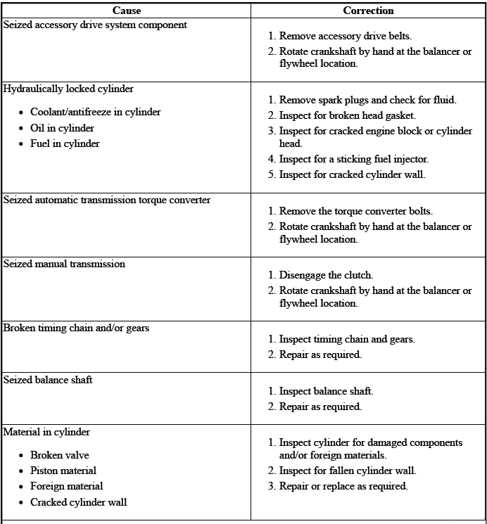
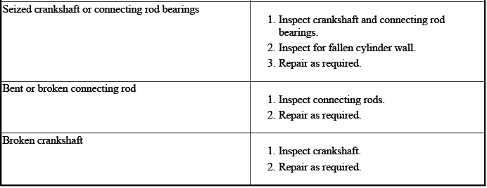
- Engine Will Not Crank - Crankshaft Will Not Rotate
- Engine Compression Test
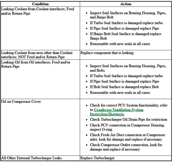
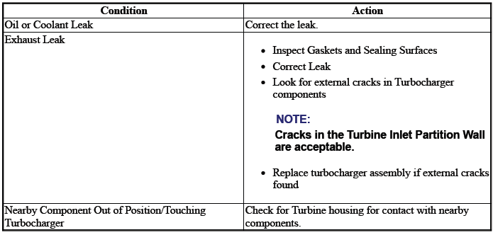
- Turbocharger Leaking Fluids Externally
- Turbocharger Noise
- Turbocharger Smoke or Smell
- Turbocharger Loss of Boost Pressure
- Oil Consumption Diagnosis
- Oil Pressure Diagnosis and Testing
- Oil Leak Diagnosis
- Drive Belt Chirping, Squeal, and Whine Diagnosis
- Drive Belt Rumbling and Vibration Diagnosis
- Drive Belt Falls Off and Excessive Wear Diagnosis
- Drive Belt Tensioner Diagnosis
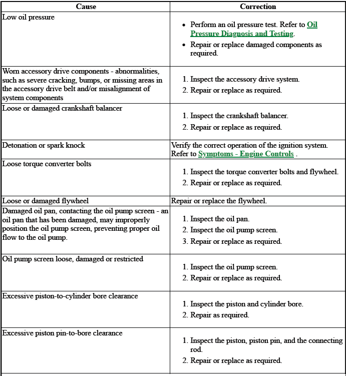
BASE ENGINE MISFIRE WITHOUT INTERNAL ENGINE NOISES
.png)
.png)
.png)
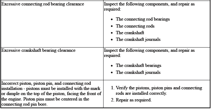
BASE ENGINE MISFIRE WITH ABNORMAL INTERNAL LOWER ENGINE NOISES
.png)
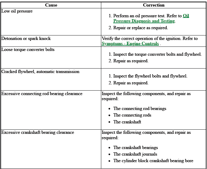
BASE ENGINE MISFIRE WITH ABNORMAL VALVE TRAIN NOISE
.png)
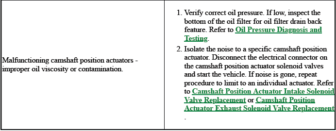
BASE ENGINE MISFIRE WITH COOLANT CONSUMPTION
.png)
BASE ENGINE MISFIRE WITH EXCESSIVE OIL CONSUMPTION
.png)
ENGINE NOISE ON START-UP, BUT ONLY LASTING A FEW SECONDS
.png)
.png)
UPPER ENGINE NOISE, REGARDLESS OF ENGINE SPEED
.png)
.png)
LOWER ENGINE NOISE, REGARDLESS OF ENGINE SPEED
ENGINE NOISE UNDER LOAD
ENGINE WILL NOT CRANK - CRANKSHAFT WILL NOT ROTATE
Coolant in Combustion Chamber
DEFINITION: Excessive white smoke and/or coolant type odor coming from the exhaust pipe may indicate coolant in the combustion chamber. Low coolant levels, an inoperative cooling fan, or a faulty thermostat may lead to an "overtemperature" condition which may cause engine component damage.
NOTE: While not always conclusive, use of hydrocarbon block test kits may reveal hydrocarbons indicating combustion chamber gases in cooling system. It is important to follow the kit instructions. This is not a substitute for service information. Combustion leak tests are available from a wide variety of aftermarket suppliers.
1. A slower than normal cranking speed may indicate coolant entering the combustion chamber. Refer to Engine Will Not Crank - Crankshaft Will Not Rotate.
2. Remove the spark plugs and inspect for spark plugs saturated by coolant or coolant in the cylinder bore.
3. Inspect by performing a cylinder leak-down test. During this test, excessive air bubbles within the coolant may indicate a faulty gasket or damaged component.
4. Inspect by performing a cylinder compression test. Two cylinders "side-by-side" on the engine block, with low compression, may indicate a failed cylinder head gasket. Refer to Engine Compression Test.

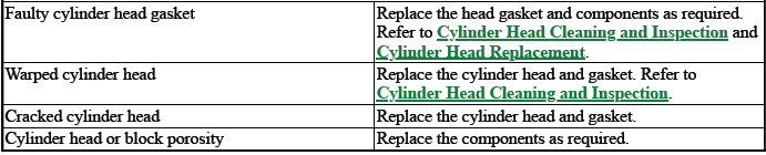
COOLANT IN ENGINE OIL
DEFINITION: Foamy or discolored oil or an engine oil "overfill" condition may indicate coolant entering the engine crankcase. Low coolant levels, an inoperative cooling fan, or a faulty thermostat may lead to an "overtemperature" condition which may cause engine component damage. Contaminated engine oil and oil filter should be changed.
1. Inspect the oil for excessive foaming or an overfill condition. Oil diluted by coolant may not properly lubricate the crankshaft bearings and may lead to component damage. Refer to Lower Engine Noise, Regardless of Engine Speed.
2. Inspect by performing a cylinder leak-down test. During this test, excessive air bubbles within the cooling system may indicate a faulty gasket or damaged component.
3. Inspect by performing a cylinder compression test. Two cylinders "side-by-side" on the engine block with low compression may indicate a failed cylinder head gasket. Refer to Engine Compression Test.
ENGINE COMPRESSION TEST
Special Tools
EN-51749 Compression Gauge Tester Kit
Equivalent regional tools: Special Tools
A compression pressure test of the engine cylinders determines the condition of the piston rings, the valves and the head gaskets.
NOTE: The battery must be at or near full charge.
1. Connect a battery charger to the battery for the duration of the test to maintain an adequate battery level.
2. Engine OFF.
3. Remove the ignition coils and spark plugs from all cylinders. Refer to Spark Plug Replacement.
4. Connect the GDS2 to the vehicle and select "Compression Test". Enabling the Compression Test will disable the fuel pump, fuel injectors, and spark. The throttle body is opened to a Wide Open Throttle (WOT) position.
The GDS2 will also automatically control the cranking procedure for many applications. If cranking control is not available use a remote start switch in place of the Starter Relay to control cranking.
5. Measure the engine compression, using the following procedure:
- Install the EN-51749 adapter into the spark plug hole.
- Install the EN-51749 gauge into the EN-51749 adapter.
NOTE: When the compression measurement is normal, the compression builds up quickly and evenly to the specified compression on each cylinder.
- Enable cranking via the GDS2 or remote start switch. When using a remote start switch, crank the engine for four compression strokes. Record the reading after the cranking cycle completes.
- Repeat the compression test for each cylinder.
6. Compare the compression readings from all of the cylinders.
- The lowest reading should not be less than 70 percent of the highest reading.
- No cylinder should read less than 690 kPa (100 psi).
- For example, if the highest pressure in any 1 cylinder is 1035 kPa (150 psi), the lowest allowable pressure for any other cylinder would be 725 kPa (105 psi). (1035 x 70% = 725) (150 x 70% = 105).
7. The following are indicators of potential problems:
- When low compression is caused by the piston rings, compression is low on the first stroke and tends to build up on the following strokes, but does not reach normal. Compression improves considerably with the addition of oil to the cylinder. Use approximately 3 squirts of oil from a plunger-type oiler into the cylinder and replace the gauge and measure again.
- When low compression is caused by the valves, the measurement is low on the first stroke and does not build up even with the addition of oil.
- Leaking head gaskets will provide the same results as worn valves but engine coolant may be identified in the crankcase. In addition, a leaking head gasket will give low readings on paired cylinders.
8. Disconnect GDS2 diagnostic tool or remote start switch.
9. Install the spark plugs for all cylinders. Refer to Spark Plug Replacement.
10. Install the ignition coils for all cylinders. Refer to Ignition Coil Replacement.
TURBOCHARGER LEAKING FLUIDS EXTERNALLY
TURBOCHARGER NOISE
Some noise is normal. Compare to a known good vehicle.
TURBOCHARGER SMOKE OR SMELL
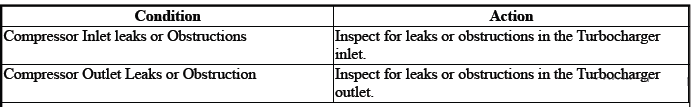
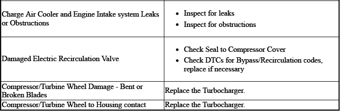
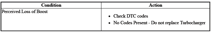
TURBOCHARGER LOSS OF BOOST PRESSURE
Cylinder Leakage Test
Special Tools
EN 35667-A Cylinder Head Leakdown Tester
For equivalent regional tools, refer to Special Tools.
NOTE: A leakage test may be performed in order to measure cylinder/combustion chamber leakage. High leakage may indicate one or more of the following:
- Worn or burnt valves
- Broken valve springs
- Stuck valve lash adjusters
- Incorrect valve lash/adjustment
- Damaged piston
- Worn piston rings
- Worn or scored cylinder bore
- Damaged cylinder head gasket
- Cracked or damaged cylinder head
- Cracked or damaged engine block
WARNING: Unless directed otherwise, the ignition must be OFF with the key removed, and all electrical loads must be OFF before servicing any electrical component. Disconnect the negative battery cable to prevent an electrical spark should a tool or equipment come in contact with an exposed electrical terminal. Failure to follow these precautions may result in personal injury and/or damage to the vehicle or its components.
For Vehicles equipped with OnStar (UE1) with Back Up Battery: The Back Up Battery is a redundant power supply to allow limited OnStar functionality in the event of a main vehicle battery power disruption to the VCIM (OnStar module). Do not disconnect the main vehicle battery or remove the OnStar fuse with the ignition key in any position other than OFF. Retained accessory power should be allowed to time out or be disabled (simply opening the driver door should disable retained accessory power) before disconnecting power. Disconnecting power to the OnStar module in any way while the ignition is On or with retained accessory power activated may cause activation of the OnStar Back-Up Battery system and will discharge and permanently damage the back-up battery. Once the Back-Up Battery is activated it will stay on until it has completely discharged. The backup battery is not rechargeable and once activated the back-up battery must be replaced.
1. Disconnect the battery ground negative cable.
2. Remove the spark plugs. Refer to Spark Plug Replacement in Engine Controls.
3. Rotate the crankshaft to place the piston in the cylinder being tested at Top Dead Center (TDC) of the compression stroke.
4. Install the EN 35667-A tester or equivalent.
NOTE: It may be necessary to hold the crankshaft balancer bolt to prevent the engine from rotating.
5. Apply shop air pressure to the EN 35667-A tester and adjust according to the manufacturers instructions.
6. Record the cylinder leakage value. Cylinder leakage that exceeds 25 percent is considered excessive and may require component service. In excessive leakage situations, inspect for the following conditions:
- Air leakage sounds at the throttle body or air inlet hose that may indicate a worn or burnt intake valve or a broken valve spring.
- Air leakage sounds at the exhaust system tailpipe that may indicate a worn or burnt exhaust valve or a broken valve spring.
- Air leakage sounds from the crankcase, oil level indicator tube, or oil fill tube that may indicate worn piston rings, a damaged piston, a worn or scored cylinder bore, a damaged engine block or a damaged cylinder head.
- Air bubbles in the cooling system may indicate a damaged cylinder head or a damaged cylinder head gasket.
7. Perform the leakage test on the remaining cylinders and record the values.
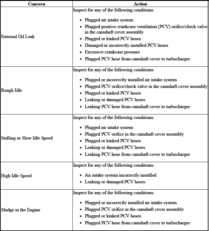
OIL CONSUMPTION DIAGNOSIS
Excessive oil consumption, not due to leaks, is the use of 0.9 L (1 qt) or greater of engine oil within 3 200 kilometers (2, 000 miles). The causes of excessive oil consumption include the following conditions:
- External oil leaks
Tighten bolts and/or replace gaskets and oil seals as necessary. - Incorrect oil level or improper reading of oil level indicator
With the vehicle on a level surface, allow adequate drain down time and inspect for the correct oil level. - Improper oil viscosity
Use recommended SAE viscosity for the prevailing temperatures. - Continuous high speed driving and/or severe usage
- Crankcase ventilation system restrictions or malfunctioning components
- Valve guides and/or valve stem oil seals worn, or the seal omitted
Ream guides and install oversize service valves and/or new valve stem oil seals. - Piston rings broken, improperly installed, worn, or not seated
properly
Allow adequate time for rings to seat. Replace broken or worn rings, as necessary. - Piston improperly installed or mis-fitted
OIL PRESSURE DIAGNOSIS AND TESTING
Special Tools
- EN-21867-850 Oil Pressure Gauge Adapter
- GE-21867-A Oil Pressure Gauge Kit
For equivalent regional tools, refer to Special Tools.
1. With the vehicle on a level surface, allow adequate drain down time of 2 - 3 minutes and measure for a low oil level.
Add the recommended grade engine oil and fill the crankcase until the oil level measures full on the oil level indicator.
2. Run the engine, and verify low, or no oil pressure on the vehicle gauge or light.
Listen for a noisy valve train or a knocking noise.
3. Inspect for the following:
- Correct oil filter with anti-drain back feature and O-ring on the cylinder block side of the filter
- Oil diluted by moisture or unburned fuel mixtures
- Improper oil viscosity for the expected temperature
- Incorrect or malfunctioning oil pressure sender
- Incorrect or malfunctioning oil pressure gauge
- Plugged oil filter
- Malfunctioning oil bypass valve
4. Remove the oil pressure sender or another engine block oil gallery plug.
5. Install EN-21867-850 adapter and GE-21867 gauge and measure the engine oil pressure.
6. Compare the readings to specifications. Refer to Engine Mechanical Specifications.
7. If the engine oil pressure is below specifications, inspect the engine for one or more of the following:
- Correct oil filter with anti-drain back feature and O-ring on the cylinder block side of the filter
- Oil pump worn or dirty
- Oil pump screen loose, plugged, or damaged
- Oil pump screen O-ring seal missing or damaged
- Malfunctioning oil control valve solenoid
- Excessive bearing clearance
- Cracked, porous or restricted oil galleries
- Oil gallery plugs missing or incorrectly installed
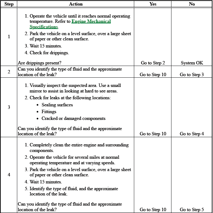
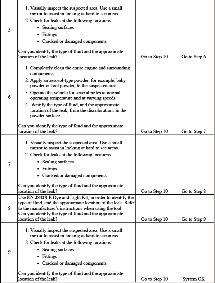
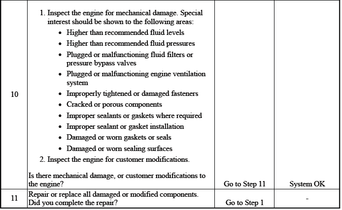
OIL LEAK DIAGNOSIS
DEFINITION: You can repair most fluid leaks by first, visually locating the leak, repairing or replacing the component, or by resealing the gasket surface. Once the leak is identified, determine the cause of the leak. Repair the cause of the leak as well as the leak itself.
CRANKCASE VENTILATION SYSTEM INSPECTION/DIAGNOSIS
Special Tools
EN 23951 Valve Manometer
For equivalent regional tools, refer to Special Tools.
1. Verify clean air cleaner.
2. Verify oil fill cap is in place.
3. Verify oil level indicator is installed.
4. Remove the oil level indicator. Install a EN 23951 valve manometer or equivalent, into the oil level indicator hole.
5. Start the engine.
6. Check for slight vacuum. The vacuum level should be less than 3.377 kPa (13.571 in H2 O).
7. If vacuum is higher, inspect and verify that the clean air hose from cam cover to air intake is not blocked or kinked.
8. If vacuum is in the normal range, remove the PCV line from the fresh air valve near oil fill cap. Block fresh air valve and also plug the fresh air hose. Vacuum should increase on the manometer. If held too long, vacuum will be drawn through the crankshaft seals creating a sucking sound.
9. If vacuum does not increase, the orifice in the camshaft cover assembly could be plugged. The valve is between the camshaft cover assembly and the cylinder head assembly.
10. If there is zero vacuum or pressure, verify compression of the engine.
11. If compression is normal, check for a blocked orifice at the camshaft cover assembly. Clean the orifice.
12. The hose from valve cover to the turbo is also for the positive crankcase ventilation (PCV) and is used for PCV flow under normal operation and only PCV flow during turbo boost conditions. If the hose is plugged, replace the PCV hose assembly and PCV fitting assembly at the turbocharger.
Drive Belt Chirping, Squeal, and Whine Diagnosis
Diagnostic Aids
- A chirping or squeal noise may be intermittent due to moisture on the drive belts or the pulleys. It may be necessary to spray a small amount of water on the drive belts in order to duplicate the customers concern. If spraying water on the drive belt duplicates the symptom, cleaning the belt pulleys may be the probable solution.
- If the noise is intermittent, verify the accessory drive components by varying their loads making sure they are operated to their maximum capacity. An overcharged A/C system, power steering system with a pinched hose or wrong fluid, or a generator failing are suggested items to inspect.
- A chirping, squeal or whine noise may be caused by a loose or improper installation of a body or suspension component. Other items of the vehicle may also cause the noise.
- The drive belts will not cause a whine noise.
Test Description
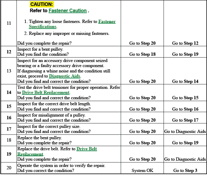
The numbers below refer to the step numbers in the diagnostic table below.
2
The noise may not be engine related. This step is to verify that the engine is making the noise. If the engine is not making the noise do not proceed further with this table.
3
The noise may be an internal engine noise. Removing the drive belts one at a time and operating the engine for a brief period will verify the noise is related to the drive belt. When removing the drive belt the water pump may not be operating and the engine may overheat. Also DTCs may set when the engine is operating with the drive belts removed.
4
Inspect all drive belt pulleys for pilling. Pilling is the small balls or pills or it can be strings in the drive belt grooves from the accumulation of rubber dust.
6
Misalignment of the pulleys may be caused from improper mounting of the accessory drive component, incorrect installation of the accessory drive component pulley, or the pulley bent inward or outward from a previous repair. Test for a misaligned pulley using a straight edge in the pulley grooves across two or three pulleys. If a misaligned pulley is found refer to that accessory drive component for the proper installation procedure for that pulley.
10
Inspecting of the fasteners can eliminate the possibility that a wrong bolt, nut, spacer, or washer was installed.
12
Inspecting the pulleys for being bent should include inspecting for a dent or other damage to the pulleys that would prevent the drive belt from not seating properly in all of the pulley grooves or on the smooth surface of a pulley when the back side of the belt is used to drive the pulley.
14
This test is to verify that the drive belt tensioner operates properly. If the drive belt tensioner is not operating properly, proper belt tension may not be achieved to keep the drive belt from slipping which could cause a squeal noise.
15
This test is to verify that the drive belt is not too long, which would prevent the drive belt tensioner from working properly. Also if an incorrect length drive belt was installed, it may not be routed properly and may be turning an accessory drive component in the wrong direction.
16
Misalignment of the pulleys may be caused from improper mounting of the accessory drive component, incorrect installation of the accessory drive component pulley, or the pulley bent inward or outward from a previous repair. Test for a misaligned pulley using a straight edge in the pulley grooves across two or three pulleys. If a misaligned pulley is found refer to that accessory drive component for the proper installation procedure for that pulley.
17
This test is to verify that the pulleys are the correct diameter or width. Using a known good vehicle compare the pulley sizes.
19
Replacing the drive belt when it is not damaged or there is not excessive pilling will only be a temporary repair.
CAUTION: Refer to Belt Dressing Caution.
DEFINITION: The following items are indications of chirping:
- A high pitched noise that is heard once per revolution of the drive belt or a pulley.
- Chirping may occur on cold damp start-ups and will subside once the vehicle reaches normal operating temp.
DEFINITION: The following items are indications of drive belt squeal:
- A loud screeching noise that is caused by a slipping drive belt. This is unusual for a drive belt with multiple ribs.
- The noise occurs when a heavy load is applied to the drive belt, such as an air conditioning compressor engagement snapping the throttle, or slipping on a seized pulley or a faulty accessory drive component.
DEFINITION: The following items are indications of drive belt whine:
- A high pitched continuous noise.
- The noise may be caused by an accessory drive component failed bearing.

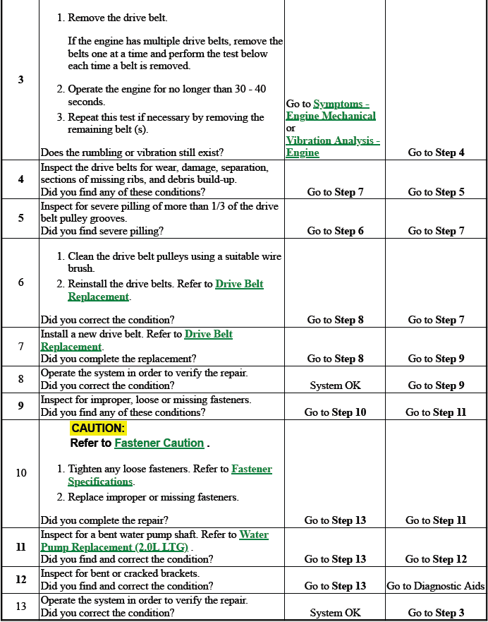
DRIVE BELT RUMBLING AND VIBRATION DIAGNOSIS
Diagnostic Aids
The accessory drive components can have an affect on engine vibration. Vibration from the engine operating may cause a body component or another part of the vehicle to make rumbling noise. Vibration can be caused by, but not limited to the A/C system over charged, the power steering system restricted or the incorrect fluid, or an extra load on the generator. To help identify an intermittent or an improper condition, vary the loads on the accessory drive components.
The drive belt may have a rumbling condition that can not be seen or felt. Sometimes replacing the drive belt may be the only repair for the symptom.
If replacing the drive belt, completing the diagnostic table, and the noise is only heard when the drive belts are installed, there might be an accessory drive component with a failure. Varying the load on the different accessory drive components may aid in identifying which component is causing the rumbling noise.
Test Description
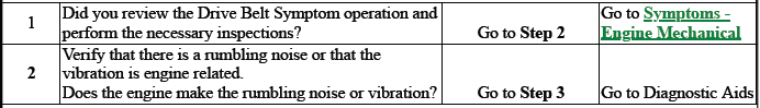
The numbers below refer to the step numbers in the diagnostic table below.
2
This test is to verify that the symptom is present during diagnosing. Other vehicle components may cause a similar symptom.
3
This test is to verify that one of the drive belts is causing the rumbling noise or vibration. Rumbling noise may be confused with an internal engine noise due to the similarity in the description. Remove only one drive belt at a time if the vehicle has multiple drive belts. When removing the drive belts the water pump may not be operating and the engine may overheat. Also DTCs may set when the engine is operating with the drive belts removed.
4
Inspecting the drive belts is to ensure that they are not causing the noise. Small cracks across the ribs of the drive belt will not cause the noise. Belt separation is identified by the plys of the belt separating and may be seen at the edge of the belt our felt as a lump in the belt.
5
Small amounts of pilling is normal condition and acceptable. When the pilling is severe the drive belt does not have a smooth surface for proper operation.
9
Inspecting of the fasteners can eliminate the possibility that the wrong bolt, nut, spacer, or washer was installed.
11
This step should only be performed if the water pump is driven by the drive belt. Inspect the water pump shaft for being bent. Also inspect the water pump bearings for smooth operation and excessive play. Compare the water pump with a known good water pump.
12
Accessory drive component brackets that are bent, cracked, or loose may put extra strain on that accessory component causing it to vibrate.
CAUTION: Refer to Belt Dressing Caution.
DEFINITION: The following items are indications of drive belt rumbling:
- A low pitch tapping, knocking, or thumping noise heard at or just above idle.
- Heard once per revolution of the drive belt or a pulley.
- Rumbling may be caused from:
- Pilling, the accumulation of rubber dust that forms small balls (pills) or strings in the drive belt pulley groove
- The separation of the drive belt
- A damaged drive belt
DEFINITION: The following items are indications of drive belt vibration:
- The vibration is engine-speed related.
- The vibration may be sensitive to accessory load.
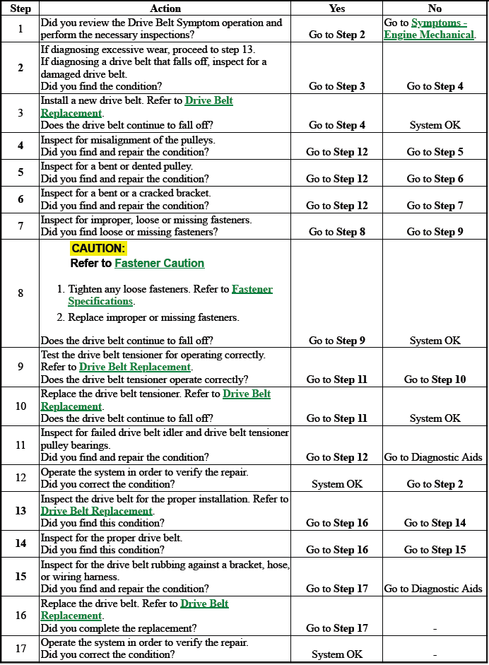
DRIVE BELT FALLS OFF AND EXCESSIVE WEAR DIAGNOSIS
Diagnostic Aids
If the drive belt repeatedly falls off the drive belt pulleys, this is because of pulley misalignment.
An extra load that is quickly applied on released by an accessory drive component may cause the drive belt to fall off the pulleys. Verify the accessory drive components operate properly.
If the drive belt is the incorrect length, the drive belt tensioner may not keep the proper tension on the drive belt.
Excessive wear on a drive belt is usually caused by an incorrect installation or the wrong drive belt for the application.
Minor misalignment of the drive belt pulleys will not cause excessive wear, but will probably cause the drive belt to make a noise or to fall off.
Excessive misalignment of the drive belt pulleys will cause excessive wear but may also make the drive belt fall off.
Test Description
The numbers below refer to the step numbers in the diagnostic table below.
2
This inspection is to verify the condition of the drive belt. Damage may of occurred to the drive belt when the drive belt fell off. The drive belt may of been damaged, which caused the drive belt to fall off. Inspect the belt for cuts, tears, sections of ribs missing, or damaged belt plys.
4
Misalignment of the pulleys may be caused from improper mounting of the accessory drive component, incorrect installation of the accessory drive component pulley, or the pulley bent inward or outward from a previous repair. Test for a misaligned pulley using a straight edge in the pulley grooves across 2 or 3 pulleys.
If a misaligned pulley is found refer to that accessory drive component for the proper installation procedure of that pulley.
5
Inspecting the pulleys for being bent should include inspecting for a dent or other damage to the pulleys that would prevent the drive belt from not seating properly in all of the pulley grooves or on the smooth surface of a pulley when the back side of the belt is used to drive the pulley.
6
Accessory drive component brackets that are bent or cracked will let the drive belt fall off.
7
Inspecting of the fasteners can eliminate the possibility that a wrong bolt, nut, spacer, or washer was installed.
Missing. loose, or the wrong fasteners may cause pulley misalignment from the bracket moving under load.
Over tightening of the fasteners may cause misalignment of the accessory component bracket.
13
The inspection is to verify the drive belt is correctly installed on all of the drive belt pulleys. Wear on the drive belt may be caused by mis-positioning the drive belt by one groove on a pulley.
14
The installation of a drive belt that is too wide or too narrow will cause wear on the drive belt. The drive belt ribs should match all of the grooves on all of the pulleys.
15
This inspection is to verify the drive belt is not contacting any parts of the engine or body while the engine is operating. There should be sufficient clearance when the drive belt accessory drive components load varies.
The drive belt should not come in contact with an engine or a body component when snapping the throttle.
CAUTION: Refer to Belt Dressing Caution.
DEFINITION: The drive belt falls off the pulleys or may not ride correctly on the pulleys.
DEFINITION: Wear at the outside ribs of the drive belt due to an incorrectly installed drive belt.
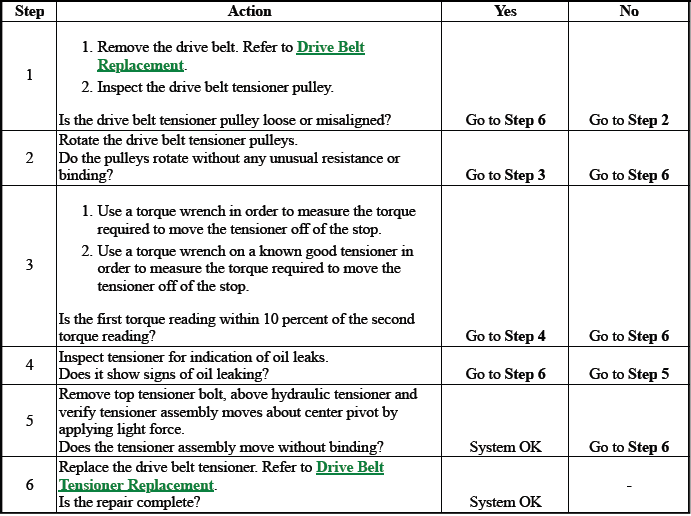
DRIVE BELT TENSIONER DIAGNOSIS
READ NEXT:
 Repair Instructions - On Vehicle
Intake Manifold Cover Replacement
Engine Oil Filler Cap
Intake Manifold Cover Bolt [3x]
Tighten
9 N.m (80 lb in)
Intake Manifold Cover
DRIVE BELT REPLACEMENT
Fig. 1: Drive Belt Routing Di
Repair Instructions - Off Vehicle
Draining Fluids and Oil Filter Removal
1.
Remove the oil filter (1). Remove the oil pan drain plug and allow the oil to
drain out.
2. Clean the oil filter housing in the engine block.
CAUTION: Refe
Description and Operation
Turbocharger System Description
Turbocharger Description and Operation
A turbocharger is a compressor that is used to increase the power output of
an engine by increasing the mass of the
oxygen and t
SEE MORE:
Additional Storage Features
Cargo Cover
Warning:
An unsecured cargo cover could
strike people in a sudden stop or
turn, or in a crash. Store the
cargo cover securely or remove it
from the vehicle.
Warning:
Do not place objects on the cargo
cover. Sudden stops or turns can
cause objects to be thrown in the
vehicle. You or other
Suspension
Opel Wheel Alignment Specifications
WHEEL ALIGNMENT SPECIFICATIONS
Insignia GNC 225/55 R17
Insignia GNC 245/40 R19
Insignia GNC 245/45 R18
Insignia GNQ 225/55 R17
Insignia GNQ 245/40 R19
Insignia GNQ 245/45 R18
