Opel Insignia: Repair Instructions - On Vehicle
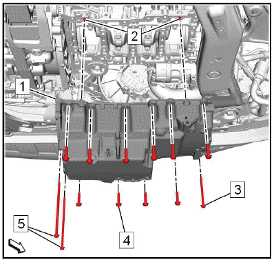
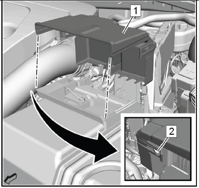
Intake Manifold Cover Replacement
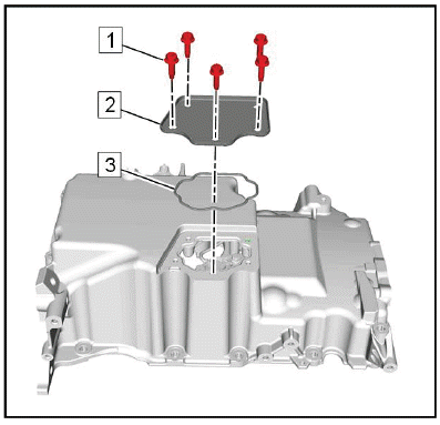
.png)
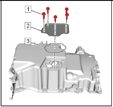
- Engine Oil Filler Cap
- Intake Manifold Cover Bolt [3x]
Tighten 9 N.m (80 lb in)
- Intake Manifold Cover
DRIVE BELT REPLACEMENT
.png)
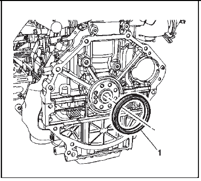
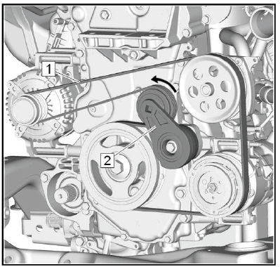
Fig. 1: Drive Belt Routing Diagram (2.0L)
Preliminary Procedure
Front Wheelhouse Liner Replacement (LTG).
- Drive Belt
Procedure- Using a suitable tool, slowly release the tension on the drive belt tensioner.
- Remove the drive belt.
DRIVE BELT TENSIONER REPLACEMENT
.png)
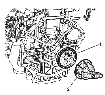
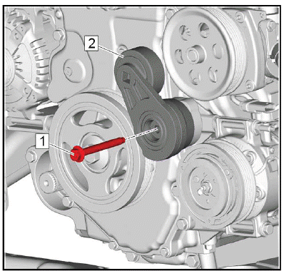
Preliminary Procedures
1. Engine Mount Replacement.
2. Drive Belt Replacement.
- Drive Belt Tensioner Fastener
CAUTION: Refer to Fastener Caution.
Tighten 58 N.m (43 lb ft) - Drive Belt Tensioner
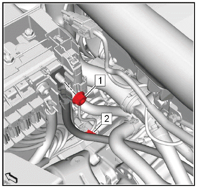
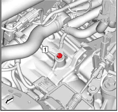
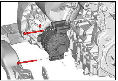
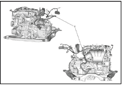
ENGINE OIL PRESSURE SENSOR REPLACEMENT
Removal Procedure
1. Exhaust Front Pipe - Remove.
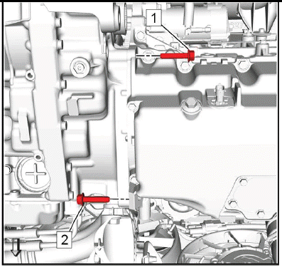
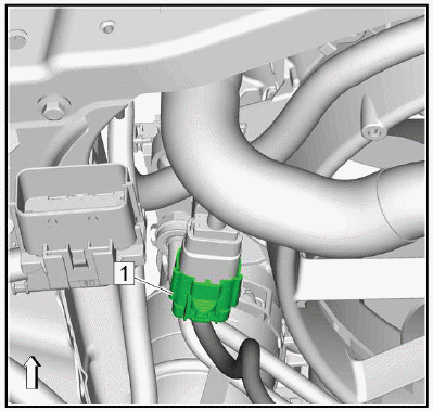
2.
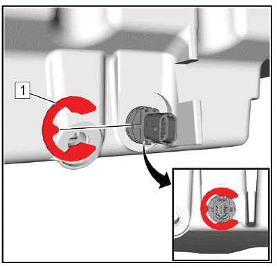
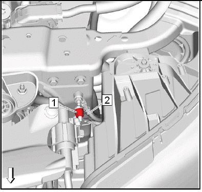
.png)
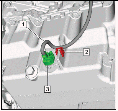
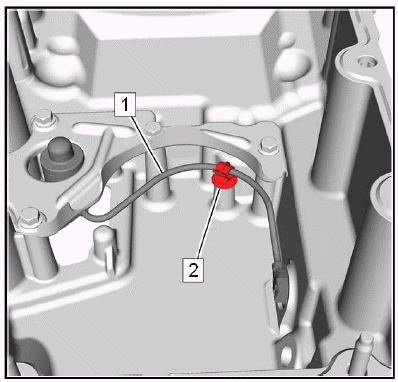
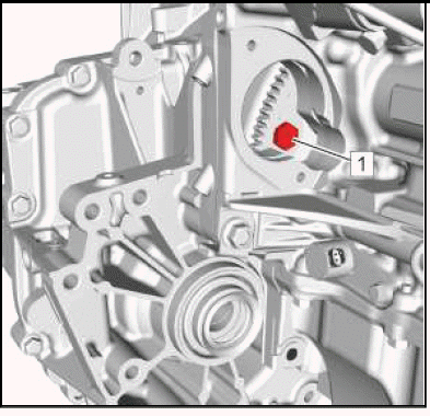
Disconnect the electrical connector. (1).
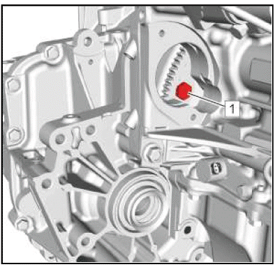
3.
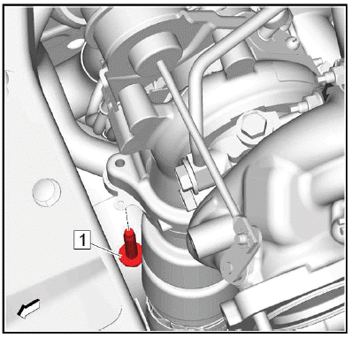
.png)
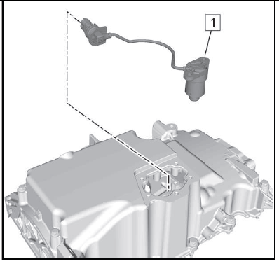
Engine Oil Pressure Sensor (1) - Remove.
Installation Procedure
1.
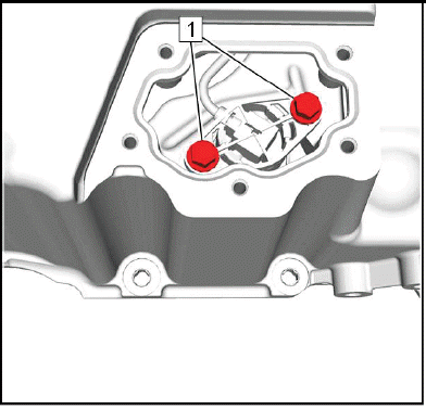
.png)
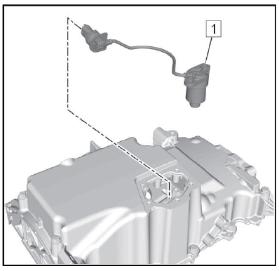
CAUTION: Fastener Caution.
Engine Oil Pressure Sensor (1) - Install and tighten35N.m (26 lb ft).
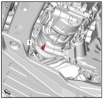
2.
.png)
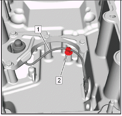
Connect the electrical connector. (1).
3. Exhaust Front Pipe - Install - Exhaust Front Pipe Replacement (LTG).
ENGINE MOUNT INSPECTION
NOTE: Before replacing any engine mount due to suspected fluid loss, verify that the source of the fluid is the engine mount, not the engine or accessories.
1. Install the engine support fixture. Refer to Engine Support Fixture. Raising the engine removes the weight from the engine mount and creates slight tension in the rubber.
2. Observe the engine mount while raising the engine. Replace the engine mount if the engine mount exhibits any of the following conditions:
- The hard rubber surface is covered with heat check cracks.
- The rubber is split through the center of the engine mount.
- The GLYCOL fluid is leaking from the engine mount.
3. Inspect the system for loose vacuum hose connections or vacuum leaks. Refer to Description and Operation.
4. Inspect the engine mount valve assemblies for loose electrical connections. Inspect the electrical system connected to the engine mount valve assemblies. Refer to Diagnostic System Check - Vehicle.
5. Inspect for the presence of glycol fluid in the vacuum system. Remove the hose assembly connections at the engine mounts. If fluid is present in the engine mount vacuum system, the entire vacuum system should be replaced.
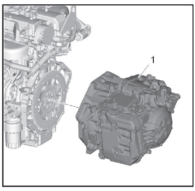
ENGINE MOUNT REPLACEMENT
Special Tools
EN-45059 Angle Meter.
Equivalent regional tools: Special Tools.
Removal Procedure
1. Remove the intake manifold cover.
2. Remove the air cleaner assembly.
3.
.png)
Install an engine lifter (1) to engine lift bracket (2) and apply tension to the engine lifter chain in order to support the engine.
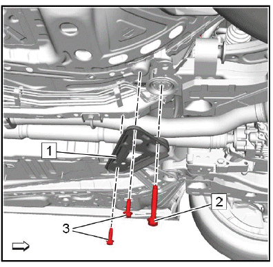
4.
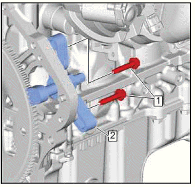
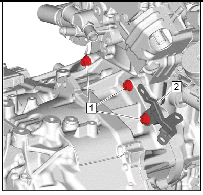
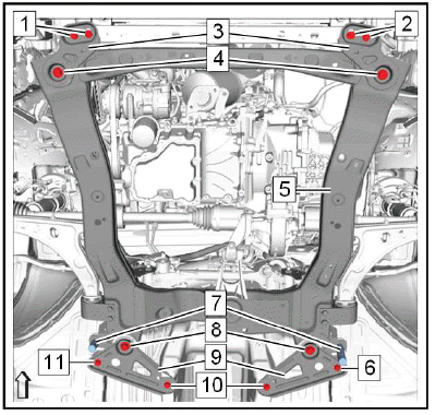
.png)
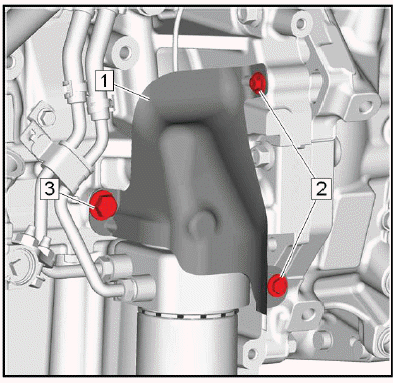
Engine Mount Brace Nut (1) - Remove.
5. Engine Mount Brace Bolt (2) - Remove.
6. Engine Mount Brace (3) - Remove.
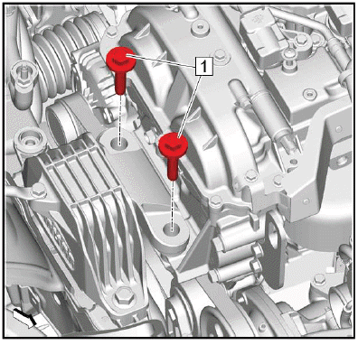
7.
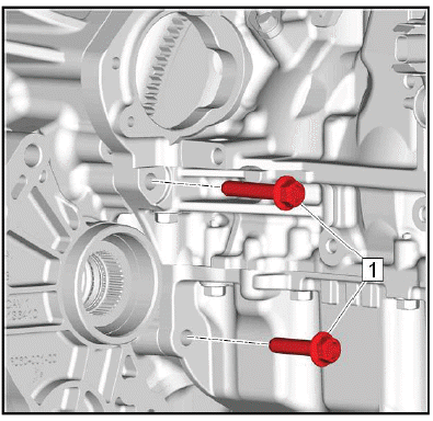
.png)
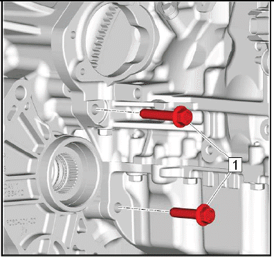
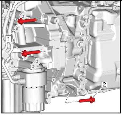
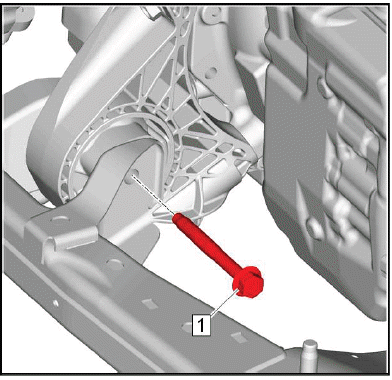
Engine Mount Bolt (1, 2) - Remove and DISCARD [4x].
8. Engine Mount (3) - Remove.
Installation Procedure
1.
.png)
Engine Mount (3) - Install.
CAUTION: Fastener Caution.
2. Engine Mount Bolt (1, 2) - Install NEW - Hand tighten.
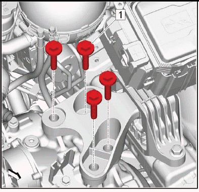
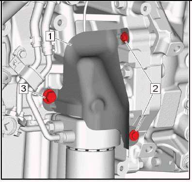
3.
.png)
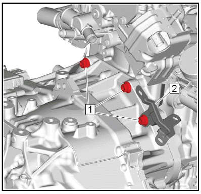
Engine Mount Brace (3) - Install.
4. Engine Mount Brace Bolt (2) - Install - Hand tighten.
5. Engine Mount Brace Nut (1) - Install - Hand tighten.
6.
.png)
CAUTION: Torque-to-Yield Fastener Caution
Engine Mount Bolt (1, 2) - Tighten in sequence
- First Pass: 100N.m (74 lb ft)
- Final Pass: 60–75 degrees - Use the special tool: EN-45059 Angle Meter
7.
.png)
Engine Mount Brace Bolt (2) - Tighten22N.m (16 lb ft).
8. Engine Mount Brace Nut (1) - Tighten22N.m (16 lb ft).
9.
.png)
Remove the engine lifter (1) from the engine lift bracket (2).
10. Install the air cleaner assembly.
11. Install the intake manifold cover.
ENGINE SUPPORT FIXTURE
.png)
Preliminary Procedures
1. Intake Manifold Cover Replacement.
2. Charge Air Cooler Outlet Air Tube Replacement.
Special Tools
- EN-51007-1 Main Support Beam
- EN-51007-3 Radiator Support Beam
- EN-51007-4 Clamp
- EN-51007-5 Support Leg, Front
- EN-51007-6 Hook
- EN-51007-7 Support Leg, Side
- EN-36857 Engine Lift Bracket
Equivalent regional tools: Special Tools.
- EN-36857 Engine Lift Bracket
Procedure
NOTE: The engine support fixture and lift brackets can be repositioned to either lift bracket to lift in desired lift points.
If engine lift brackets are not present, install EN-36857 engine lift brackets as needed. - EN-51007-7 Support Leg, Side
Procedure
NOTE: Ensure that the engine support fixture only contacts the frame in the area indicated by arrows. Do not install on top of fender lip.
Install the EN-51007-7 Support Leg, Side to frame as shown. - EN-51007-4 Clamp
- EN-51007-1 Main Support Beam
- Z EN-51007-3 Radiator Support Beam
- EN-51007-5 Support Leg, Front
- EN-51007-6 Hook
Turbocharger Heat Shield Replacement
.png)
- Turbocharger Heat Shield Bolt [3x]
CAUTION: Refer to Fastener Caution.
NOTE: In the event that a bolt breaks upon removal of components, perform an extraction of the broken bolt.
Tighten 14 N.m (10 lb ft) - Turbocharger Heat Shield
TURBOCHARGER REPLACEMENT
Removal Procedure
CAUTION: If a turbocharger has failed, clean any turbocharger debris or excessive oil from the charge air cooler system before installing the new turbocharger. Failure to clean debris from the charge air cooler system will cause severe turbocharger and engine damage upon startup.
1. Intake Manifold Cover Replacement - Remove.
2. Air Cleaner Outlet Duct Replacement - Remove.
3.
.png)
Turbocharger Heat Shield (2) - Remove.
4. Turbocharger Coolant Return Pipe Replacement - Remove.
5. Warm Up Three-Way Catalytic Converter Replacement (2.0L LTG) - Remove.
6. Turbocharger Oil Return Pipe Replacement - Remove.
7. Raise and support the vehicle.
8.
.png)
Turbocharger Oil Feed Pipe Bolt (1) - Remove [2X].
9. Turbocharger Coolant Feed Pipe Replacement - Remove.
10. Charge Air Cooler Inlet Air Tube Replacement - Remove.
11. Lower the vehicle.
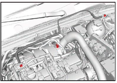
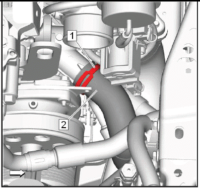
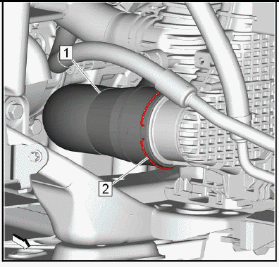
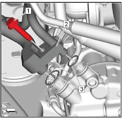
.png)
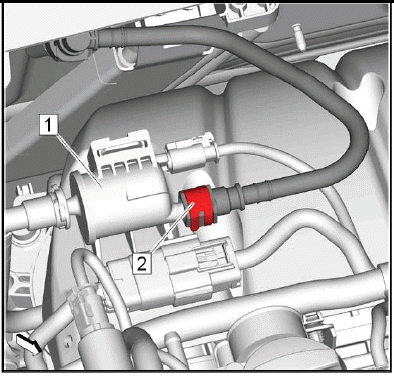
NOTE: The PCV hose and fitting assembly connection is permanent. Reinstall these components as an assembly unless new components are being used.
NOTE: Always ensure the PCV hose fitting O-Ring (3) seal is free of cuts or abrasions each time the fitting is attached to the turbocharger.
Positive Crankcase Ventilation Hose Fitting Bolt (1) - Remove.
13. Positive Crankcase Ventilation Hose Fitting (2) - Disconnect.
14. Disconnect the electrical connectors from the turbocharger.
15.
.png)
NOTE: The exhaust pipe studs do not come installed on new turbochargers. If the turbocharger is being replaced, new studs will need to be installed.
Turbocharger Nut (1) - Remove and DISCARD [4x].
16. Turbocharger (2) - Remove.
17. Turbocharger Gasket (3) - Remove and DISCARD.
18. Turbocharger Oil Feed Pipe Gasket (4) - Remove and DISCARD.
19. Turbocharger (2) - Clean and inspect - Refer to Camshaft Cover and Compressor Air Intake Turbocharger Cleaning and Inspection.
20. Transfer components as necessary.
Installation Procedure
1.
.png)
NOTE: Install a NEW gasket.
Turbocharger Oil Feed Pipe Gasket (4) - Install.
NOTE: Install a NEW gasket.
2. Turbocharger Gasket (3) - Install.
3. Turbocharger (2) - Install.
NOTE: Install NEW nuts.
NOTE: The exhaust pipe studs do not come installed on new turbochargers. If the turbocharger is being replaced, new studs will need to be installed.
4. Turbocharger Nut (1) - Loosely install [4x].
5.
.png)
CAUTION: Refer to Fastener Caution.
CAUTION: This component uses torque-to-yield bolts. When servicing this component do not reuse the bolts, New torque-to-yield bolts must be installed. Reusing used torque-to-yield bolts will not provide proper bolt torque and clamp load.
Failure to install NEW torque-to-yield bolts may lead to engine damage.
Turbocharger Nut - Tighten in sequence.
Tighten
- First Pass: 30 N.m (22 lb ft)
- Final Pass: an additional 90 degrees
6.
.png)
NOTE: Always ensure the PCV hose fitting O-Ring (3) seal is free of cuts or abrasions each time the fitting is attached to the turbocharger.
Inspect the O-ring and replace if necessary. (3).
7. Positive Crankcase Ventilation Hose Fitting (2) - Connect.
8. Positive Crankcase Ventilation Hose Fitting Bolt (1) - Install and tighten8 N.m (71 lb in).
9. Raise and support the vehicle. Lifting and Jacking the Vehicle.
10.
.png)
CAUTION: Refer to Fastener Caution.
Turbocharger Oil Feed Pipe Bolt (1) - Install and tighten [2X]10 N.m (89 lb in).
11. Lower the vehicle. Lifting and Jacking the Vehicle.
12. Turbocharger Coolant Feed Pipe Replacement - Install.
13. Turbocharger Coolant Return Pipe Replacement - Install.
14. Warm Up Three-Way Catalytic Converter Replacement (2.0L LTG) - Install.
15. Turbocharger Oil Return Pipe Replacement - Install.
16. Charge Air Cooler Inlet Air Tube Replacement - Install.
17. Connect the turbocharger electrical connectors.
18.
.png)
Turbocharger Heat Shield (2) - Install - Turbocharger Heat Shield Replacement.
19. Air Cleaner Outlet Duct Replacement - Install.
20. Intake Manifold Cover Replacement - Install.
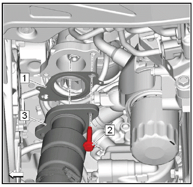
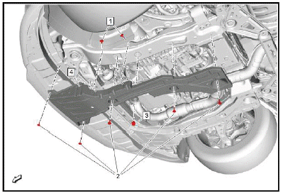
TURBOCHARGER OIL RETURN PIPE REPLACEMENT
Removal Procedure
1. Warm Up Three-Way Catalytic Converter Replacement (2.0L LTG) - Remove.
2. Raise and support the vehicle. Lifting and Jacking the Vehicle.
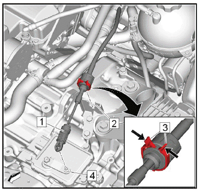
3.
.png)
Turbocharger Oil Return Pipe Bolt (1) - Remove [2x].
4.
.png)
Turbocharger Oil Return Pipe Bolt (1) - Remove [2x].
5. Turbocharger Oil Return Pipe (2) - Remove.
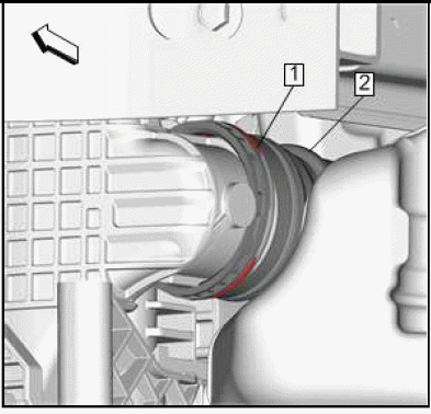
6.
.png)
Turbocharger Oil Return Pipe Gasket (1) - Remove and DISCARD [2x].
Installation Procedure
1.
.png)
NOTE: Install a NEW gasket.
Turbocharger Oil Return Pipe Gasket (1) - Install [2x]
2.
.png)
Turbocharger Oil Return Pipe (2) - Install
CAUTION: Refer to Fastener Caution.
3. Turbocharger Oil Return Pipe Bolt (1) - Install and tighten [2x]10 N.m (89 lb in).
4.
.png)
Turbocharger Oil Return Pipe Bolt (1) - Install and tighten [2x]10 N.m (89 lb in).
5. Warm Up Three-Way Catalytic Converter Replacement (2.0L LTG) - Install.
6. Lower the vehicle. Lifting and Jacking the Vehicle
TURBOCHARGER OIL FEED PIPE REPLACEMENT
.png)
Preliminary Procedure
Turbocharger Replacement.
- Turbocharger Oil Feed Pipe Bolt
CAUTION: Refer to Fastener Caution.
Tighten 35 N.m (26 lb ft) - Turbocharger Oil Feed Pipe Washer [2x]
Procedure
Install NEW sealing washers. - Turbocharger Oil Feed Pipe Gasket
Procedure
Install a NEW gasket. - Turbocharger Oil Feed Pipe
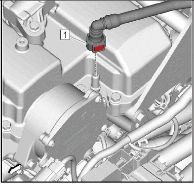
Positive Crankcase Ventilation Valve Replacement
.png)
Preliminary Proced80ure
Intake Manifold Cover Replacement.
NOTE: Inspect each component while attached to the camshaft cover.
Do not remove the PCV
components unless inspection indicates a suspect component. Replace the PCV
valve, PCV
tube assembly, and PCV hose fitting as an assembly. The connections between
these
components are permanent.
- Positive Crankcase Ventilation Valve
Bolt
CAUTION: Refer to Fastener Caution.
Tighten 8 N.m (71 lb in) - Positive Crankcase Ventilation Valve
Procedure
Inspect the PCV valve. If the PCV valve is suspect, use a suitable tool to pry the valve off of the
cover. Retrieve any particles that fall onto the baffle in the cover. Discard the valve and particles.
NOTE: When the PCV valve is removed, small particles of the valve will break and fall into the cover. - Positive Crankcase Ventilation Valve
Fitting Seal
NOTE: Inspect the seal and replace as needed.
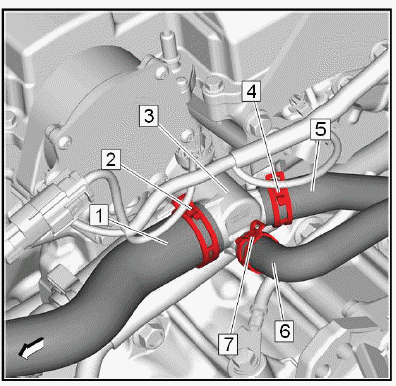
POSITIVE CRANKCASE VENTILATION HOSE/PIPE/TUBE REPLACEMENT
Special Tools
- EN-50956 Tamper Proof Drive Bit
Equivalent regional tools: Special Tools.
Removal Procedure
1. Intake Manifold Cover Replacement - Remove.
2. Positive Crankcase Ventilation Tube @ Air Cleaner Outlet Duct - Disconnect.
3.
.png)
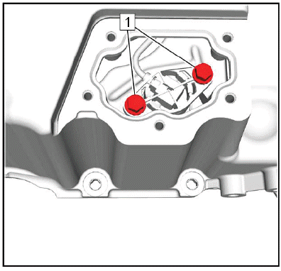
NOTE: PCV Valve fasteners are tamper proof and must have a slot cut in the fastener to be removed.
Using a suitable cutting tool, cut a slot in the fasteners. Remove the PCV valve fasteners with a flat blade screw driver and DISCARD (1).
4. Remove the PCV hose fastener (2) from the camshaft cover.
NOTE: PCV valves and PCV tube assembly have tamper-proof connections and cannot be disassembled.
5. Remove the PCV valves and PCV tube assembly.
Installation Procedure
1.
.png)
Install the PCV hose assembly and PCV valves (3).
CAUTION: Refer to Fastener Caution.
2. Install the NEW PCV valve fasteners (1) using EN-50956 tamper proof drive bit and tighten to 10 N.m (89 lb in).
3. Install the PCV hose fastener (2) and tighten to 12 N.m (106 lb in).
4. Positive Crankcase Ventilation Tube @ Air Cleaner Outlet Duct - Connect.
5. Intake Manifold Cover Replacement - Install.
INTAKE MANIFOLD REPLACEMENT
Removal Procedure
1. Intake Manifold Cover - Remove.
2. Charge Air Cooler Outlet Air Tube - Remove.
3. Fuel Feed Front Pipe - Remove.
4. Engine Coolant Air Bleed Hose - Remov.
NOTE: The Positive Crankcase Ventilation (PCV) tube has a tamper-proof fitting and cannot be disconnected without damage to the PCV tube. Only disconnect the PCV tube if replacing the air cleaner outlet duct. If repositioning the air cleaner outlet duct, leave the PCV tube connected.
5. Positive Crankcase Ventilation Tube - Remove.
6.
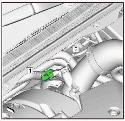
.png)
Evaporative Emission Canister Purge Solenoid Valve (1) - Remove.
7. Throttle Body Assembly - Remove.
8. Fuel Pump - Remove.
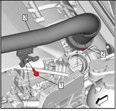
9.
.png)
Disengage the intake manifold cover clips (1) then remove the cover (2).
10.
.png)
NOTE: The intake manifold bolts are retained in the intake manifold. If the bolts cause clearance concerns, secure them as needed using tape.
Fully loosen the intake manifold bolts (1) in order to remove the intake manifold.
NOTE: The fuel injection fuel rail fuel pressure sensor must be removed to obtain enough clearance to remove the intake manifold from the vehicle.
11. Separate the intake manifold from the engine to gain access to the fuel pressure sensor.
12. Fuel Injection Fuel Rail Fuel Pressure Sensor - Remove.
13. Remove the intake manifold. (2).
14.
.png)
Remove and DISCARD the gasket.
15. Clean and inspect the intake manifold.
Installation Procedure
1.
.png)
Install a NEW intake manifold gasket. (1).
2. Fuel Injection Fuel Rail Fuel Pressure Sensor - Install.
3.
.png)
NOTE: When installing the intake manifold, ensure that the gasket seal is securely installed prior to positioning the intake manifold.
Install the intake manifold. (2)
NOTE: If tape has been installed to ease intake manifold removal, remove the tape.
4. Start all bolts by hand before tightening. (1)
.png)
Fig. 2: Intake Manifold Bolts Tightening Sequence
5. CAUTION: Fastener Caution.
Tighten the intake manifold bolts in the sequence shown.
- First Pass: 12N.m (106 lb in)
- Final Pass: 12N.m (106 lb in)
6.
.png)
Position the intake manifold cover (2) over the intake manifold then engage the clips (1) to secure the cover.
7. Fuel Pump - Install.
8. Throttle Body Assembly - Install.
9.
.png)
Evaporative Emission Canister Purge Solenoid Valve (1) - Install.
10. Engine Coolant Air Bleed Hose - Remove.
11. Charge Air Cooler Outlet Air Tube - Remove.
12. Fuel Feed Front Pipe - Remove.
13. Intake Manifold Cover - Remove.
CRANKSHAFT BALANCER REPLACEMENT
Special Tools
- EN-45059 Angle Meter
- EN-51577 Crankshaft Balancer Holder/Remover
- J-41816-2 or EN-38416-2 Crankshaft End Protector
Equivalent regional tools: Special Tools
Removal Procedure
1. Remove the drive belt.
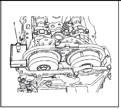
2.
.png)
Use EN-51577-1 Crankshaft Balancer Remover (1) and breaker bar (2) prevent the crankshaft from rotating while loosening the crankshaft balancer fastener (3).
3. Remove and DISCARD the crankshaft balancer fastener (3).
4.
.png)
Remove the crankshaft balancer holder then install the J-41816-2 or EN-38416-2 Crankshaft End Protector (1) and all components of EN-51577 Crankshaft Balancer Remover (2, 3) as shown.
5.
.png)
Tighten the crankshaft balancer remover (1) in order to remove the crankshaft balancer (2).
Installation Procedure
1.
.png)
Install the crankshaft balancer with NEW fastener. Use EN-51577-1 Crankshaft Balancer Remover (1) and breaker bar (2) prevent the crankshaft from rotating while tightening the NEW crankshaft balancer fastener (3).
CAUTION: Refer to Fastener Caution.
2. Tighten the crankshaft balancer bolt to 150 N.m (111 lb ft) plus an additional 140 degrees using the EN-45059 meter.
3. Install the drive belt. Drive Belt Replacement.
TIMING CHAIN CRANKSHAFT SPROCKET REPLACEMENT
Special Tools
- EN-51577-1 Crankshaft Balancer Remover
- EN-50837 Timing Chain Tensioner Retraction Tool
For equivalent regional tools, refer to Special Tools.
Removal Procedure
1. Remove the camshaft cover. Refer to Camshaft Cover Replacement.
2. Remove the timing chain. Refer to Camshaft Timing Chain and Tensioner Replacement.
3.
.png)
Remove the balancer chain tensioner bolt (1).
4. Remove the balancer chain tensioner (2).
5. Compress and lock the tensioner using EN-50837 retention tool.
- Insert EN-50837 retention tool into the lever arm and push in a counterclockwise direction.
- Compress the tensioner while holding lever arm.
- Relax the force on the lever and tensioner slightly, allowing the tensioner to extend 3 ratchet clicks, and then hold in place.
- Pull lever clockwise using EN-50837 retention tool until the hole in the lever aligns with the hole in the tensioner assembly. Push the point of EN-50837 retention tool through the lever and into the tensioner assembly.
6.
.png)
Remove the balancer chain guide bolt (1).
7. Remove the balancer chain guide (2).
8.
.png)
NOTE: The crankshaft balancer and the ORIGINAL balancer bolt will be temporarily installed in order to counter hold the crankshaft while removing the balancer shaft driven sprocket bolt.
TEMPORARILY install the crankshaft balancer (1).
- TEMPORARILY install the ORIGINAL crankshaft balancer bolt (2).
- Counter hold the crankshaft balancer pulley (1) using the EN-51577-1 Crankshaft Balancer Remover (3).
- While counter holding, remove and DISCARD the balancer shaft driven sprocket bolt (4).
- Remove the crankshaft balancer bolt (2), balancer (1) and tool (3).
9.
.png)
Remove the crankshaft sprocket, balancer shaft driven sprocket, and balancer chain (1) simultaneously.
Installation Procedure
1.
.png)
NOTE: Proper setup is critical to ensure correct timing when installing the sprockets and chain simultaneously onto the shafts. The timing links are heat treated blued steel.
Assemble the crankshaft sprocket, balancer shaft driven sprocket, and balancer chain. Ensure the timing link (1) lines up with the timing mark (2) on the crankshaft sprocket. Ensure that both timing teeth (3) on the balancer shaft driven sprocket line up with the timing links (4).
2.
.png)
NOTE: The crankshaft keyway should be in the 12 O'clock position.
Install the sprockets and chain (1) as an assembly to the crankshaft and balancer shaft assembly.
3.
.png)
Ensure the timing link (1) is aligned with the crankshaft sprocket timing mark (2).
4. Ensure the adjacent timing links (4) are aligned with both of the timing marks (3) on the balancer shaft driven sprocket.
5.
.png)
NOTE: The crankshaft balancer and the ORIGINAL balancer bolt will be temporarily installed again in order to counter hold the crankshaft while tightening the balancer shaft driven sprocket bolt.
Hand start the NEW balancer shaft driven sprocket bolt (4).
- TEMPORARILY install the crankshaft balancer (1).
- TEMPORARILY install the ORIGINAL crankshaft balancer bolt (2).
- Counter hold the crankshaft balancer pulley (1) using the EN-51577-1 Crankshaft Balancer Remover (3).
CAUTION: This vehicle is equipped with torque-to-yield or single use fasteners.
Install a NEW torque-to-yield or single use fastener when installing this component. Failure to replace the torque-to-yield or single use fastener could cause damage to the vehicle or component.
CAUTION: Refer to Fastener Caution.
- Counter hold the crankshaft balancer using the EN-51577-1 Crankshaft Balancer Remover (3).
- While counter holding, tighten the balancer shaft driven sprocket bolt (4) to 40 N.m (30 lb ft) plus 50 degrees
NOTE: A NEW crankshaft balancer bolt will be installed during final installation of the crankshaft balancer.
- Remove and DISCARD the crankshaft balancer bolt (2).
- Remove the crankshaft balancer (1) and EN-51577-1 Crankshaft Balancer Remover (3).
6.
.png)
NOTE: Ensure the guide is installed in the correct orientation. The long end must point toward the crankshaft and the flat edge must be adjacent to the balance chain.
Install the balancer chain guide (2).
7. Install the balancer chain guide bolts (1). Tighten the bolts to 10 N.m (89 lb in).
8.
.png)
Install the balancer chain tensioner (2).
9. Install the balancer chain tensioner bolts (1). Tighten the bolts to 10 N.m (89 lb in).
10. Remove EN-50837 retention tool to restore the tension to the balancer chain.
11. Install the timing chain. Refer to Camshaft Timing Chain and Tensioner Replacement.
12. Install the camshaft cover. Refer to Camshaft Cover Replacement.
CRANKSHAFT FRONT OIL SEAL REPLACEMENT
.png)
Preliminary Procedure
Crankshaft Balancer Replacement.
- Crankshaft Front Oil Seal
Procedure- Use a suitable tool to remove the seal.
- Use the EN 50820 Front Crankshaft Seal Installer to install the seal.
Special Tools
EN 50820 Front Crankshaft Seal Installer
Equivalent regional tools: Special Tools
Engine Front Cover Replacement
Special Tools
- EN-45059 Angular Meter
- EN-50820 Front Crankshaft Seal Installer
- KM-470 - B Angular Torque Gauge
Equivalent regional tools: Special Tools
Removal Procedure
1. Air Cleaner Assembly - Remove.
2. Camshaft Cover Replacement - Remove.
3. Engine Mount Replacement - Remove.
4. Crankshaft Balancer Replacement - Remove.
5. Drive Belt Tensioner Replacement - Remove.
6.
.png)
NOTE: Only bolts 3, 5 and 6 will be replaced with NEW bolts.
Engine Front Cover Bolt (3, 5 and 6) - Remove and DISCARD.
7. Engine Front Cover Bolt (2-7, 9) - Remove.
8. Engine Front Cover (1) - Remove.
9. If replacing the engine front cover, remove and DISCARD the crankshaft front oil seal using an appropriate tool.
Installation Procedure
1.
.png)
If removed, Use EN-50820 installer, to install the front crankshaft seal (1) into the engine front cover.
2.
.png)
NOTE:
- The engine front cover surface must be free of contamination prior to applying the sealer.
- Install and align the cover within 20 minutes of applying the sealer.
- The cover must be fastened to final torque specification within 60 minutes of applying the sealer.
- Additional sealant is necessary to reduce the possibility of leakage where the cylinder head to engine block interface along the bead path flange on the front cover.
Apply a 5 mm bead of sealer directly in the flange (1) of the engine front cover perimeter mating surface. Also apply a 5 mm bead of sealer directly to the locations indicated (2). Finally, apply a 14 mm dab of sealant at the locations indicated (3).
3.
.png)
Install the engine front cover (1).
CAUTION: Refer to Fastener Caution.
CAUTION: This vehicle is equipped with torque-to-yield or single use fasteners. Install a NEW torque-to-yield or single use fastener when installing this component.
Failure to replace the torque-to-yield or single use fastener could cause damage to the vehicle or component.
NOTE: Only bolts 3, 5 and 6 will be replaced with NEW bolts.
4. Install by hand 3 NEW M10 bolts (3, 5, 6) in the engine front cover, as shown.
5. Hand start the remaining engine front cover bolts (2, 4, 7, 8).
.png)
Fig. 3: Engine Front Cover Bolts Tightening Sequence
6.
CAUTION: Refer to Fastener Caution.
Tighten the engine front cover bolts in sequence to final torque twice:
Tighten
- Tighten sequence 1 - 3 bolts a first pass to 15 N.m (11 lb ft).
- Tighten sequence 1 - 3 bolts a final pass 130 degrees using EN-45059 meter.
- Tighten sequence 4 - 15 bolts to 25 N.m (18 lb ft).
- Tighten sequence 16 - 17 bolts to 10 N.m (7 lb ft)
- Tighten sequence 18 - 19 bolts to 10 N.m (7 lb ft).
- Tighten sequence 20 bolt to 25 N.m (18 lb ft).
7. Drive Belt Tensioner Replacement - Install.
8. Crankshaft Balancer Replacement - Install.
9. Engine Mount Replacement - Install.
10. Camshaft Cover Replacement - Install.
11. Air Cleaner Assembly - Install.
INTAKE VALVE ROCKER ARM REPLACEMENT
Removal Procedure
1. Remove the camshaft position actuator and camshaft - intake. Refer to Camshaft Position Actuator and Camshaft Replacement - Intake.
2.
.png)
NOTE: Keep all of the valve rocker arms and hydraulic lash adjusters in order so that they can be reinstalled in their respective locations.
Remove the intake rocker arm (1).
Installation Procedure
1.
.png)
Lubricate the valve tips. Refer to Adhesives, Fluids, Lubricants, and Sealers.
2.
.png)
NOTE:
- Used rocker arms must be returned to the original position on the camshaft. If the camshaft is being replaced, the rocker arms actuated by the camshaft must also be replaced.
- Pre-oil roller bearings before installation.
Lubricate the roller bearings with valve rocker arm lubricant. Refer to Adhesives, Fluids, Lubricants, and Sealers.
3. Position the valve rocker arm (1) on the tip of the valve stem and on the lash adjuster and lubricate. Refer to Adhesives, Fluids, Lubricants, and Sealers.
4. Install the camshaft position actuator and camshaft - intake. Refer to Camshaft Position Actuator and Camshaft Replacement - Intake.
EXHAUST VALVE ROCKER ARM REPLACEMENT
Removal Procedure
1. Remove the camshaft position actuator and camshaft - exhaust. Refer to Camshaft Position Actuator and Camshaft Replacement - Exhaust.
2.
.png)
NOTE: Keep all of the Valve Rocker Arms and hydraulic lash adjusters in order so that they can be reinstalled in their respective locations.
Remove the exhaust rocker arm (1).
Installation Procedure
1.
.png)
Lubricate the valve tips. Refer to Adhesives, Fluids, Lubricants, and Sealers.
2.
.png)
NOTE:
- Used rocker arms must be returned to the original position on the camshaft. If the camshaft is being replaced, the rocker arms actuated by the camshaft must also be replaced.
- Pre-oil roller bearings before installation.
Lubricate the roller bearings with valve rocker arm lubricant. Refer to Adhesives, Fluids, Lubricants, and Sealers.
3. Position the valve rocker arm (1) on the tip of the valve stem and on the lash adjuster and lubricate. Refer to Adhesives, Fluids, Lubricants, and Sealers.
4. Install the camshaft position actuator and camshaft - exhaust. Refer to Camshaft Position Actuator and Camshaft Replacement - Exhaust.
Camshaft Timing Chain and Tensioner Replacement
Removal Procedure
1. Remove the engine front cover. Refer to Engine Front Cover Replacement.
2.
.png)
Remove the upper timing chain guide bolts (2, 3).
3. Remove the upper timing chain guide (1).
4.
.png)
Timing Chain Tensioner Bolt (1) - Remove [2x].
5. Timing Chain Tensioner (2) - Remove.
6. Timing Chain Tensioner Gasket (3) - Remove and DISCARD.
7.
.png)
Remove the timing chain tensioner pivot arm bolt (1).
8. Remove the timing chain tensioner pivot arm (2).
9.
.png)
Remove the timing chain guide bolts (1).
10. Remove the timing chain guide (2).
11.
.png)
Remove the timing chain (1).
12.
.png)
Remove the timing chain oil nozzle (1).
13. For camshaft timing chain, sprocket, and tensioner cleaning and inspection. Refer to Camshaft Timing Chain, Sprocket, and Tensioner Cleaning and Inspection.
Installation Procedure
1.
.png)
NOTE: Ensure the timing chain oil nozzle is rotated with the notch facing upward, and aligned with the tab on the engine block.
Install the timing chain oil nozzle (1).
2.
.png)
NOTE: There are three colored links on the timing chain. The two links that align to the timing marks on the actuators are the same color. The timing link that aligns with the timing mark on the crankshaft sprocket is a unique color. Use the following procedure to line up the links with the actuators. Orient the chain so that the colored links are visible.
Loop the timing chain over the intake and exhaust camshaft actuators, aligning one of the same colored links (2) with the timing mark on the exhaust camshaft actuator (3).
NOTE: The same colored link corresponding to the intake actuator will not initially align with the intake actuator timing mark, nor the unique colored timing chain link align with the crankshaft sprocket timing mark.
3. Ensure the crankshaft key in the 12 O'clock position. Loop the timing chain onto the crankshaft sprocket.
4.
.png)
NOTE: Timing will be established before the final install and torque of the guide bolts.
Install the timing chain guide (2) and upper bolt (1) only, finger tight.
5. Install the timing chain tensioner pivot arm (3).
6. Install the pivot arm bolt (1) finger tight.
7.
.png)
With a suitable tool, rotate the crankshaft counterclockwise to align the timing mark on the crankshaft sprocket (1) with the timing link (2).
NOTE:
- Continue to rotate the crankshaft counterclockwise as necessary to maintain timing alignment.
- Ensure that the alignment mark on the exhaust camshaft actuator remains aligned with the timing link.
8. Rotate the lower end of the fixed timing chain guide into installation position and install the lower bolt (3).
9. Tighten the timing chain guide upper and lower bolts to 25 N.m (18 lb ft).
10.
.png)
NOTE:
- The timing for the exhaust camshaft actuator and the crankshaft sprocket has been established.
- Applying or loosening pressure by hand between the timing chain guides will allow the chain to slip or bind during counterclockwise rotation of the camshaft.
Using a suitable tool, rotate the intake camshaft counterclockwise until the timing mark on the intake actuator (2) is aligned with the timing link (1). Maintain tension on intake camshaft until the timing chain tensioner can be installed and activated.
11.
.png)
NOTE: Use a NEW gasket.
Timing Chain Tensioner Gasket (3) - Install.
12. Timing Chain Tensioner (2) - Install.
13. Timing Chain Tensioner Bolt (1) - Install and tighten [2x]25 N.m (18 lb ft).
14.
.png)
Verify the timing links on the timing chain are properly aligned to the timing marks:
- The timing links (1, 2) are aligned to the appropriate timing marks on the camshaft actuators (6, 3).
- The unique colored link (5) is aligned to the timing mark on the crankshaft sprocket (4).
15. If they are not, repeat the portion of the procedure necessary to align the timing marks.
16.
.png)
Install the timing chain guide (1) and bolts (2, 3) finger tight.
.png)
Fig. 4: Front Camshaft Cap Bolts Tightening Sequence
17.
Tighten the front camshaft cap bolts in sequence to 10 N.m (7 lb ft) twice.
18. Rotate the crankshaft clockwise to see if either of the actuators or the crankshaft sprocket jump timing chain teeth. If this occurs, repeat procedure to align the timing marks.
19.
.png)
NOTE: Due to the difference of crankshaft sprocket and balance shaft sprocket, timing marks on the chain will not match during every crankshaft revolution.
Ensure that the marks on the sprockets are aligned appropriately before installing the timing chain.
Rotate the crankshaft slightly in clockwise direction to allow chain to settle on actuator and sprocket teeth. If the timing chain jumps actuator teeth, repeat procedure to align the timing marks.
20. Verify the timing links on both the timing chain & balance chain are properly aligned to the timing marks:
- The timing link (1) is aligned to the timing mark on the crankshaft sprocket (2).
- The adjacent timing links (4) are aligned with both timing marks (3) on the balancer shaft driven sprocket.
21.
.png)
NOTE: Because of slight clockwise rotation all chain marks may be advanced slightly in relation to the actuator and sprocket marks, yet still align.
The timing chain links (1, 2) are aligned to the appropriate timing marks on the camshaft actuators (6, 3).
22. Install the engine front cover. Refer to Engine Front Cover Replacement.
BALANCER SHAFT WITH OIL PUMP REPLACEMENT
Removal Procedure
1. Oil Pan Replacement - Remove.
2. Timing Chain Crankshaft Sprocket Replacement - Remove.
3.
.png)
Balancer Shaft with Oil Pump Bolt (1) - Remove [8x].
4. Balancer Shaft with Oil Pump (2) - Remove.
NOTE: If replacing the oil pump, remove it from the balancer shaft.
5. Remove the oil pump.
Installation Procedure
1. Install the oil pump.
2.
.png)
Balancer Shaft with Oil Pump (2) - Install.
3. Balancer Shaft with Oil Pump Bolt (1) - Loosely install [8x].
.png)
Fig. 5: Engine Balancer Shaft And Oil Pump Bolts Tightening Sequence
4.
Balancer Shaft with Oil Pump Bolt - Tighten in sequence [8x]
Tighten
- First pass 58 N.m (43 lb ft)
- Final pass 58 N.m (43 lb ft)
5. Timing Chain Crankshaft Sprocket Replacement - Install.
6. Oil Pan Replacement - Install.
CAMSHAFT COVER REPLACEMENT
Removal Procedure
1. Ignition Coil Replacement - Remove.
2. Vacuum Pump Replacement - Remove.
3. Positive Crankcase Ventilation Tube @ Air Cleaner Outlet Duct - Disconnect.
4. Turbocharger Heat Shield Replacement - Remove.
5.
.png)
NOTE: The PCV hose and fitting assembly (2) is a permanent connection. Reinstall these components as an assembly unless new components are being used.
NOTE: Always ensure the PCV hose fitting O-Ring (3) seal is free of cuts or abrasions each time the fitting is attached to the turbocharger.
Positive Crankcase Ventilation Hose Fitting Bolt (1) - Remove.
6. Positive Crankcase Ventilation Hose Fitting (2) - Disconnect.
7. Turbocharger Coolant Return Pipe Replacement - Remove.
8. Oil Level Indicator - Remove.
9. Engine Coolant Air Bleed Pipe Replacement (2.0L LTG) - Remove.
10. Camshaft Position Actuator Intake Solenoid Valve Replacement - Remove.
11. Camshaft Position Actuator Exhaust Solenoid Valve Replacement - Remove.
12. Camshaft Cover Heat Shield Replacement - Remove.
13.
.png)
NOTE: Note the location of the four long camshaft cover bolts (2) for proper installation.
Camshaft Cover Bolt (1, 2) - Remove.
14. Camshaft Cover (3) - Remove.
15.
.png)
Camshaft Cover Gasket (1) - Remove and DISCARD.
16. If reinstalling the camshaft cover (2), clean and inspect as needed. Refer to Camshaft Cover and Compressor Air Intake Turbocharger Cleaning and Inspection.
Installation Procedure
1.
.png)
NOTE: Install a NEW gasket.
NOTE: Add 14mm bead of sealant at right and left T-Joint where front cover meets head and at rear of camshaft cover right and left T-Joint where vacuum pump bolts on.
Camshaft Cover Gasket (1) - Install.
2.
.png)
Camshaft Cover (3) - Install.
NOTE: Ensure the long camshaft cover bolts (2) are installed in the correct positions.
3. Camshaft Cover Bolt (1, 2) - Loosely install.
.png)
Fig. 6: Camshaft Cover Bolts Tightening Sequence
4.
Tighten the camshaft cover bolts in sequence to 10 N.m (89 lb in).
5. Camshaft Cover Heat Shield Replacement - Install.
6.
.png)
NOTE: Always ensure the PCV hose fitting O-Ring seal (3) is free of cuts or abrasions each time the fitting is attached to the turbocharger.
Inspect the O-ring and replace if necessary. (3)
7. Positive Crankcase Ventilation Hose Fitting (2) - Connect.
8. Positive Crankcase Ventilation Hose Fitting Bolt (1) - Install and tighten8 N.m (71 lb in).
9. Camshaft Position Actuator Exhaust Solenoid Valve Replacement - Install.
10. Camshaft Position Actuator Intake Solenoid Valve Replacement - Install.
11. Install the engine oil level indicator.
12. Turbocharger Heat Shield Replacement - Install.
13. Turbocharger Coolant Return Pipe Replacement - Install.
14. Engine Coolant Air Bleed Pipe Replacement (2.0L LTG) - Install.
15. Positive Crankcase Ventilation Tube @ Air Cleaner Outlet Duct - Connect.
16. Vacuum Pump Replacement - Install.
17. Ignition Coil Replacement - Install.
Timing Chain Tensioner Replacement
.png)
Preliminary Procedure
Engine Front Cover Replacement.
- Timing Chain Tensioner Bolt [2x]
CAUTION: Refer to Fastener Caution.
Tighten 25 N.m (18 lb ft) - Timing Chain Tensioner
- Timing Chain Tensioner Gasket
Install NEW
HYDRAULIC VALVE LASH ADJUSTER REPLACEMENT - EXHAUST
Removal Procedure
1. Remove the exhaust valve rocker arm. Refer to Exhaust Valve Rocker Arm Replacement.
2.
.png)
Remove the hydraulic lash adjusters (1).
Installation Procedure
1.
.png)
NOTE: Pre-fill the low pressure chamber with engine oil. Maintain a vertical orientation of the assembly to retain the oil in the reservoir and high pressure chamber. Do not install the lash adjusters without pre-filling the low pressure chamber. Apply engine oil to the outer diameter surface of all adjusters.
Lubricate and install the hydraulic valve lash adjusters (1) into their bores in the cylinder head. Refer to Adhesives, Fluids, Lubricants, and Sealers.
2. Install the exhaust valve rocker arm. Refer to Exhaust Valve Rocker Arm Replacement.
HYDRAULIC VALVE LASH ADJUSTER REPLACEMENT - INTAKE
Removal Procedure
1. Remove the intake valve rocker arm. Refer to Intake Valve Rocker Arm Replacement.
2.
.png)
Remove the hydraulic lash adjusters (1).
Installation Procedure
1.
.png)
NOTE: Pre-fill the low pressure chamber with engine oil. Maintain a vertical orientation of the assembly to retain the oil in the reservoir and high pressure chamber. Do not install the lash adjusters without pre-filling the low pressure chamber. Apply engine oil to the outer diameter surface of all adjusters.
Lubricate and install the hydraulic valve lash adjusters (1) into their bores in the cylinder head. Refer to Adhesives, Fluids, Lubricants, and Sealers.
2. Install the intake valve rocker arm. Refer to Intake Valve Rocker Arm Replacement.
CAMSHAFT POSITION ACTUATOR AND CAMSHAFT REPLACEMENT - INTAKE
Special Tools
- EN-50656 Holding Tool
- EN 50793 Locking Tool
For equivalent regional tools, refer to Special Tools.
Removal Procedure
NOTE: Ensure the engine is properly timed to Top Dead Center (TDC), prior to performing repairs.
1. Remove the camshaft cover. Refer to Camshaft Cover Replacement.
2. Remove the high pressure fuel pump. Refer to Fuel Pump Replacement.
3.
.png)
NOTE: Ensure the EN-50656 holding tool is installed and securely tightened to prevent the camshaft chain from dropping into the front engine cover during camshaft actuator replacement.
Install EN-50656 timing chain holding tool (1) and tighten to 8 N.m (71 lb in).
4.
.png)
NOTE: Ensure to mark actuator sprocket and chain before removal.
Align and install camshaft actuator locking tool (2) EN 50793 into the slots of the exhaust camshaft actuator and mount tool to engine front cover assembly and tighten the bolts (1) to 10 N.m (89 lb in).
5.
.png)
Remove and DISCARD the camshaft actuator bolt (1).
6.
.png)
Remove the EN-50793 holding tool (2).
7.
.png)
Remove the upper timing chain guide bolts (1, 2).
8. Remove the upper timing chain guide (3).
9. Remove the camshaft front bearing cap bolts (4).
NOTE: Locate the pry points (6) in the camshaft front bearing cap. When using the 3 pry points to remove the front bearing cap evenly, use a protective material between the camshaft lobes, the cylinder head flange, and pry tool.
10. Remove the camshaft front bearing cap (5).
11.
.png)
Mark the exhaust camshaft rear cap to ensure it is installed in the same position. Remove the exhaust camshaft bearing rear cap bolts (1) and cap (2).
NOTE: Loosen each bolt on each cap one turn at a time until there is no spring tension pushing on the camshaft.
12. Mark the camshaft caps (4) to ensure they are installed in the same position.
13. Remove the exhaust camshaft cap bolts (3).
14. Remove the camshaft caps (4).
15.
.png)
Pull exhaust camshaft actuator assembly forward away from camshaft assembly (1), then lift rear of exhaust camshaft assembly to a tilt and pull free from exhaust camshaft actuator assembly (2).
16.
.png)
Mark the intake camshaft rear cap to ensure it is installed in the same position. Remove the intake camshaft bearing rear cap bolts (1) and cap (2).
NOTE: Loosen each bolt on each cap one turn at a time until there is no spring tension pushing on the camshaft.
17. Mark the camshaft caps (4) to ensure they are installed in the same position.
18. Remove the intake camshaft cap bolts (3).
19. Remove the camshaft caps (4).
20. Lift and roll intake camshaft assembly from original position over into exhaust camshaft position within engine head assembly.
21.
.png)
Align and install camshaft actuator locking tool (2) EN 50793 into the slots of the intake camshaft actuator and mount tool to engine front cover assembly and tighten the bolts (1) to 10 N.m (89 lb in).
22.
.png)
Remove the camshaft actuator bolt (1).
23.
.png)
Remove the EN-50793 holding tool (2).
24.
.png)
Pull intake camshaft actuator assembly forward away from camshaft assembly (1), then lift rear of intake camshaft assembly to a tilt and pull free from intake camshaft actuator assembly (2).
NOTE: If replacing the camshaft, ensure to transfer any marking from the old camshaft to the new one.
25. Replace the camshaft if necessary.
Installation Procedure
1.
.png)
Install the intake camshaft (1) and camshaft actuator (2).
2.
.png)
Align and install camshaft actuator locking tool (2) EN 50793 into the slots of the intake camshaft actuator and mount tool to engine front cover assembly and tighten the bolts (1) to 10 N.m (89 lb in).
3.
.png)
Install a NEW camshaft actuator bolt (1) and tighten to 30 N.m (22 lb ft) plus 100 degrees.
4. Lift and roll intake camshaft assembly from exhaust camshaft position over into original position.
5.
.png)
NOTE: Apply lubricant to all lobes and journals prior to installing the camshafts.
Set the intake camshaft on top of the roller followers in the camshaft bearing journals with the intake actuator timing mark at approximately the 11 O'clock position.
NOTE: To properly position the camshaft caps, install the camshaft cap bolts into the camshaft caps prior to installing the camshaft caps on the camshafts.
6. Install the camshaft cap bolts (1, 3) into the camshaft caps (2, 4).
7. Install the camshaft caps (2, 4) and hand start the camshaft cap bolts (1, 3).
8.
.png)
Install the exhaust camshaft (1) and camshaft actuator (2).
9.
.png)
Align and install camshaft actuator locking tool (2) EN 50793 into the slots of the intake camshaft actuator and mount tool to engine front cover assembly and tighten the bolts (1) to 10 N.m (89 lb in).
10.
.png)
Install a NEW camshaft actuator bolt (1) and tighten to 30 N.m (22 lb ft) plus 100 degrees.
11.
.png)
NOTE: Apply lubricant to all lobes and journals prior to installing the camshafts.
Set the exhaust camshaft on top of the roller followers in the camshaft bearing journals with the exhaust actuator timing mark at approximately the one O'clock position.
NOTE: To properly position the camshaft caps, install the camshaft cap bolts into the camshaft caps prior to installing the camshaft caps on the camshafts.
12. Install the camshaft cap bolts (1, 3) into the camshaft caps (2, 4).
13. Install the camshaft caps (2, 4) and hand start the camshaft cap bolts (1, 3).
14.
.png)
Install the front camshaft bearing cap (1). Install the timing chain guide (2) onto the front camshaft bearing cap, then hand start the camshaft cap bolts (3 - 5).
.png)
Fig. 7: Camshaft Cam Bolts Tightening Sequence
15.
NOTE: During the tightening sequence, locate and tighten each camshaft cap bolt installed into the circular hole first. Then, tighten the bolt installed into the slotted hole.
Tighten the camshaft cap bolts in sequence using the following procedure:
- Tighten the camshaft cap bolts in sequence to 8 N.m (71 lb in).
- Loosen both bolts in each cap in sequence to 180 degrees.
- Tighten the camshaft cap bolts in sequence to 10 N.m (89 lb in) twice.
16.
.png)
Tighten the front camshaft cap bolts in sequence to 10 N.m (89 lb in) twice.
17.
.png)
Remove EN-50656 timing chain holding tool (1).
18. Install the high pressure fuel pump. Refer to Fuel Pump Replacement.
19. Install the camshaft cover. Refer to Camshaft Cover Replacement.
Camshaft Position Actuator and Camshaft Replacement - Exhaust
Special Tools
- EN-50656 Holding Tool
- EN 50793 Locking Tool
For equivalent regional tools, refer to Special Tools.
Removal Procedure
NOTE: Ensure the engine is properly timed to Top Dead Center (TDC), prior to performing repairs.
1. Remove the camshaft cover. Refer to Camshaft Cover Replacement.
2.
.png)
NOTE: Ensure the EN-50656 Holding tool is installed and securely tightened to prevent the camshaft chain from dropping into the front engine cover during camshaft actuator replacement.
Install EN-50656 timing chain holding tool (1) and tighten to 8 N.m (71 lb in).
3.
.png)
NOTE: Ensure to mark actuator sprocket and chain before removal.
Align and install camshaft actuator locking tool (2) EN 50793 into the slots of the exhaust camshaft actuator and mount tool to engine front cover assembly and tighten the bolts (1) to 10 N.m (89 lb in).
4.
.png)
Remove and DISCARD the camshaft actuator bolt (1).
5.
.png)
Remove the EN-50793 holding tool (2).
6.
.png)
Remove the upper timing chain guide bolts (1, 2).
7. Remove the upper timing chain guide (3).
8. Remove the camshaft front bearing cap bolts (4).
NOTE: Locate the pry points (6) in the camshaft front bearing cap. When using the 3 pry points to remove the front bearing cap evenly, use a protective material between the camshaft lobes, the cylinder head flange, and pry tool.
9. Remove the camshaft front bearing cap (5).
10.
.png)
Mark the exhaust camshaft rear cap to ensure it is installed in the same position. Remove the exhaust camshaft bearing rear cap bolts (1) and cap (2).
NOTE: Loosen each bolt on each cap one turn at a time until there is no spring tension pushing on the camshaft.
11. Mark the camshaft caps (4) to ensure they are installed in the same position.
12. Remove the exhaust camshaft cap bolts (3).
13. Remove the camshaft caps (4).
14.
.png)
Pull exhaust camshaft actuator assembly forward away from camshaft assembly (1), then lift rear of exhaust camshaft assembly to a tilt and pull free from exhaust camshaft actuator assembly (2).
NOTE: If replacing the camshaft, ensure to transfer any marking from the old camshaft to the new one.
15. Replace the camshaft if necessary.
Installation Procedure
1.
.png)
Install the exhaust camshaft (1) and camshaft actuator (2).
2.
.png)
Align and install camshaft actuator locking tool (2) EN 50793 into the slots of the intake camshaft actuator and mount tool to engine front cover assembly and tighten the bolts (1) to 10 N.m (89 lb in).
3.
.png)
Install a NEW camshaft actuator bolt (1) and tighten to 30 N.m (22 lb ft) plus 100 degrees.
4.
.png)
NOTE: Apply lubricant to all lobes and journals prior to installing the camshafts.
Set the exhaust camshaft on top of the roller followers in the camshaft bearing journals with the exhaust actuator timing mark at approximately the one O'clock position.
NOTE: To properly position the camshaft caps, install the camshaft cap bolts into the camshaft caps prior to installing the camshaft caps on the camshafts.
5. Install the camshaft cap bolts (1, 3) into the camshaft caps (2, 4).
6. Install the camshaft caps (2, 4) and hand start the camshaft cap bolts (1, 3).
7.
.png)
Install the front camshaft bearing cap (1). Install the timing chain guide (2) onto the front camshaft bearing cap, then hand start the camshaft cap bolts (3 - 5).
8.
.png)
NOTE: During the tightening sequence, locate and tighten each camshaft cap bolt installed into the circular hole first. Then, tighten the bolt installed into the slotted hole.
Install the camshaft cap bolts in sequence using the following procedure:
- Tighten the camshaft cap bolts in sequence to 8 N.m (71 lb in).
- Loosen both bolts in each cap in sequence to 180 degrees.
- Tighten the camshaft cap bolts in sequence to 10 N.m (89 lb in) twice.
9.
.png)
Tighten the front camshaft cap bolts in sequence to 10 N.m (89 lb in) twice.
10.
Remove EN-50656 timing chain holding tool (1).
11. Install the camshaft cover. Refer to Camshaft Cover Replacement.
CAMSHAFT COVER HEAT SHIELD REPLACEMENT
Preliminary Procedures
1. Intake Manifold Cover Replacement.
2. Turbocharger Heat Shield Replacement.
3. Disconnect and reposition the engine wiring harness.
- Camshaft Cover Heat Shield Bolt [4x]
CAUTION: Refer to Fastener Caution.
Tighten 10 N.m (89 lb in) - Camshaft Cover Heat Shield
Procedure
Disconnect the camshaft position actuator solenoid valve.
NOTE: When removing the camshaft cover heat shield, carefully guide the shield past the turbocharger coolant return and PCV pipes.
VALVE STEM OIL SEAL AND VALVE SPRING REPLACEMENT
Special Tools
- EN-37281-A Valve Guide Seal Remover
- EN-50717 Valve Spring Compressor
- EN-50792 Flywheel Holding Tool
Equivalent regional tools: Special Tools
Removal Procedure
NOTE: Prevent the crankshaft from rotating clockwise or counterclockwise before using compressed air in the cylinder. Rotation of the crankshaft may cause damage to EN-50792 Flywheel Holding Tool.
1. If equipped with a manual transmission, leave the transmission in first gear with the vehicle on the ground and the parking brake set.
2. If equipped with an automatic transmission, remove the starter.
4. Remove the camshaft.
5. Valve Rocker Arm - Remove
6.
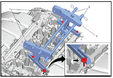
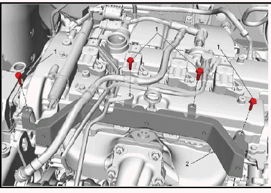
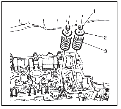
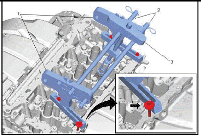
NOTE: When mounting the valve spring compressor to the cylinder head, a suitable large washer should be used as indicated by the arrow.
Install the EN-50717 Valve Spring Compressor (1) to the front and rear of the cylinder head as shown.
7. Install the cross bars and locks (2) of the EN-50717 Valve Spring Compressor to the valve spring compressor adaptors.
8. Remove the spark plugs.
9. Install an air hose adapter into the spark plug hole.
10. Attach an air hose to the adapter and pressurize the cylinder to 690 kPa (100 psi).
11. Compress the valve spring using the valve spring compressor (3).
12.
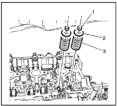
Remove the valve spring keepers (1).
13. Remove the valve spring (3) and retainer (2).
14. Use the EN-37281-A Valve Guide Seal Remover to remove the valve seal.
Installation Procedure
1. Using the EN-37281-A Valve Guide Seal Remover, install the NEW valve seal. Fully seat the seal onto the valve guide.
2.
Install the valve spring (3) and retainer (2).
3. Compress the valve spring using the valve spring compressor.
4. Install the valve spring keepers (1).
5. Disconnect the air hose and air hose adapter.
6.
Remove the EN-50717 Valve Spring Compressor and EN-50717 Valve Spring Compressor adapter set from the cylinder head.
7. Install the spark plugs.
8. Valve Rocker Arm - Install.
9. Install the camshaft.
10. Remove the EN-50792 Flywheel Holding Tool.
11. If equipped with an automatic transmission, install the starter.
Cylinder Head Replacement
Removal Procedure
Special Tools
- EN-38188 Cylinder Head Broken Bolt Extractor Kit - or equivalent aftermarket tool
- EN-45059 Angle Meter
- EN-36857 Engine Lift Bracket
Equivalent regional tools: Special Tools
1. Cooling System Draining and Filling (Static) Cooling System Draining and Filling (GE 47716) - Drain.
2. Camshaft Cover Replacement - Remove.
3. Fuel Pump Replacement - Remove.
4. Intake Manifold Replacement - Remove.
5. Exhaust Manifold Replacement - Remove.
6. Engine Front Cover Replacement - Remove.
7. Camshaft Position Actuator and Camshaft Replacement - Intake - Remove.
8. Camshaft Position Actuator and Camshaft Replacement - Exhaust - Remove.
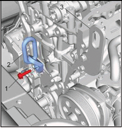
9.
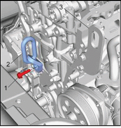
Install the EN-36857 Engine Lift Bracket (2) and fastener (1) into the engine block.
NOTE: Support the engine as necessary from underneath while repositioning the engine support fixture.
10. Reposition the engine support fixture lift hook from the engine lift bracket (3) to the EN-36857 Engine Lift Bracket (2) 11.
Cylinder Head Bolt - Remove and DISCARD.
12.
CAUTION: In order to prevent damage to the valves and injectors during cylinder head removal, set the cylinder head on blocks.
Cylinder Head Bolt (1) - Remove and DISCARD [10x].
13. Cylinder Head (2) - Remove.
14. Cylinder Head Gasket (3) - Remove and DISCARD.
15. Replace or transfer locating pins as necessary.
16. Use the following procedures when cleaning the cylinder head and cylinder block surfaces:
- Be careful not to gouge or scratch the gasket surfaces. Do not gouge or scrape the combustion chamber surfaces. The feel of the gasket surface is important, not the appearance. There will be indentations from the gasket left in the cylinder head after all of the gasket material is removed. These small indentations will be filled in by the new gasket.
- Use a gasket scraper to clean the cylinder head and cylinder block gasket surfaces. Do not scratch or gouge any surface.
- Do not use any other method or technique to clean these gasket surfaces.
NOTE: Do not use a tap to clean the cylinder head bolt holes.
17. Clean the old sealer/lube and dirt from the bolt holes.
18. Clean the bolt holes with a nylon bristle brush.
WARNING: Wear safety glasses to avoid injury when using compressed air or any cleaning solvent. Bodily injury may occur if fumes are inhaled or if skin is exposed to chemicals.
19. When cleaning the cylinder head bolt holes use a suitable commercial spray liquid solvent and compressed air from an extended-tip blow gun to reach the bottom of the holes.
20. Remove any broken long cylinder head bolts using the EN 38188 kit.
21. If replacing the cylinder head, transfer all parts as necessary.
22. Cylinder Head - Clean and inspect.
Installation Procedure
1. If replacing the cylinder head, transfer all parts as necessary.
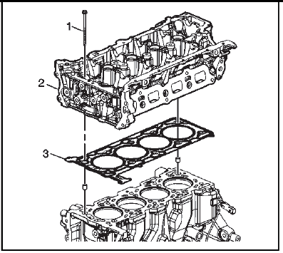
2.
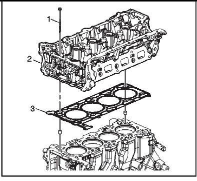
NOTE: Do not use any sealing material.
NOTE: Install a NEW gasket.
Cylinder Head Gasket (3) - Install.
3. Ensure the number 1 cylinder is at top dead center (TDC). The key on the crankshaft should be on top in the 12 o'clock position.
4. Cylinder Head (2) - Install.
5. Install NEW bolts.
Cylinder Head Bolt (1) - Loosely install [10x].
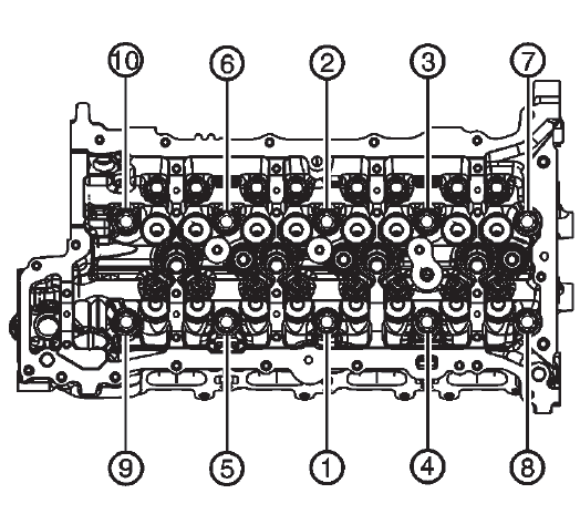
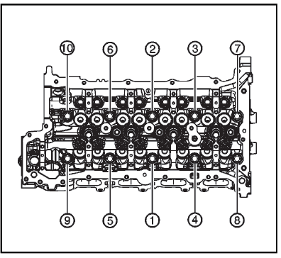
Fig. 8: Cylinder Head Bolts Tightening Sequence
6.
Tighten in the sequence shown.
Tighten
- First Pass: tighten the bolts in sequence to 30 N.m (22 lb ft).
- Final Pass: tighten the bolts an additional 190 degrees in sequence using the EN 45059 meter.
7.
Support engine as necessary from underneath to allow repositioning the engine support lift fixture hook to the EN-36857 Engine Lift Bracket (2). Engine Support Fixture.
8. Reposition the engine support fixture lift hook from the EN-36857 Engine Lift Bracket (2) to the engine lift bracket (3).
9. Remove the EN-36857 Engine Lift Bracket (2) and fastener (1) from the engine block.
10. Camshaft Position Actuator and Camshaft Replacement - Intake - Install.
11. Camshaft Position Actuator and Camshaft Replacement - Exhaust - Install.
12. Engine Front Cover Replacement - Install.
13. Exhaust Manifold Replacement - Install.
14. Intake Manifold Replacement - Install.
15. Fuel Pump Replacement - Install.
16. Camshaft Cover Replacement - Install.
17. Change the engine oil and filter.
18. Cooling System Draining and Filling (Static) Cooling System Draining and Filling (GE 47716) - Fill.
OIL PAN REPLACEMENT
Removal Procedure
1. Support the engine.
2. Drain the engine oil.
3. Remove the engine front cover.
4. Exhaust Front Pipe - Remove.
5. Remove the catalytic converter. Warm Up Three-Way Catalytic Converter. Replacement (2.0L LTG).
6. Remove the engine oil cooler.
7. Front Compartment Air Deflector - Right Side - Remove.
8. Power Transfer Unit Case - Remove.
9.
.png)
Air Conditioning Compressor Bolt (1) - Remove.
10.
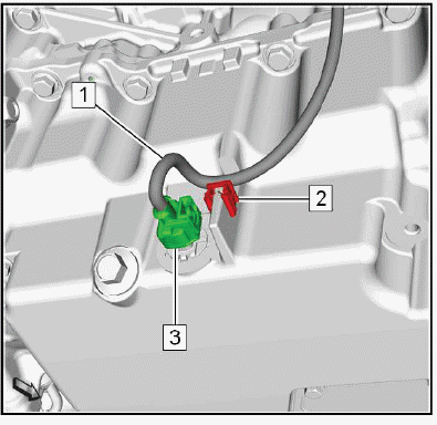
Wiring Harness Retainer (2) - Remove.
11. Disconnect the electrical connector. (3)
12. Wiring Harness (1) - Position aside.
13.
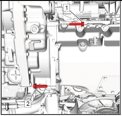
Transmission Bolt (1, 2) - Remove [2x].
14.
NOTE: Take note that there are different bolt lengths.
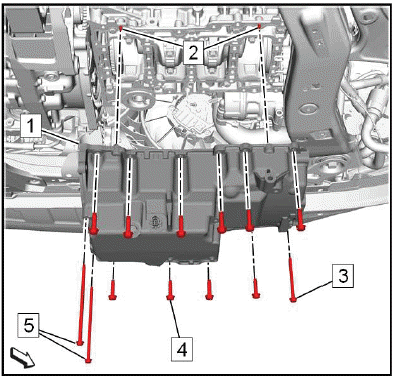
Oil Pan Bolt (3, 4, 5) - Remove [13x].
15. Remove the oil pan. (1)
16. Ensure that the location pins (2) are in the lower crankcase.
Disassemble Procedure
1. Engine Oil Level Indicator Switch - Remove.
Assemble Procedure
1. Engine Oil Level Indicator Switch - Install.
2. Clean the sealing surface of the engine block and the engine front cover from old gasket material, oil, dirt and grease.
Installation Procedure
1.
NOTE:
- The lower crankcase surface must be free of contamination prior to applying the sealer.
- Install and align the oil pan to block within 10 minutes of applying the sealer.
- The oil pan must be fastened to final torque specification within 60 minutes of applying the sealer.
Clean the sealing surface of the lower crankcase and the engine front cover from old gasket material, oil, dirt and grease.
2. In case of reusing the old oil pan, clean and inspect the oil pan.
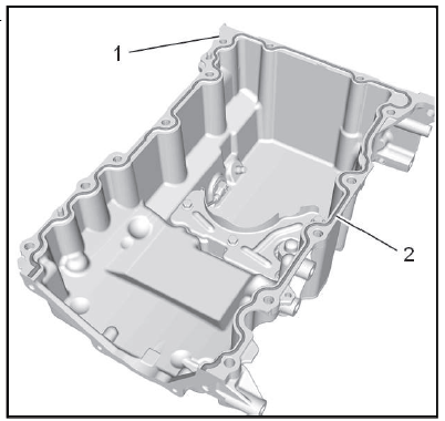
3. Apply a 4.25 mm (0.167 in) bead of sealer (2) on the level part of the flange around the perimeter of the oil pan (1) as shown.
4.
NOTE: When installing the oil pan, carefully align the oil pan (1) to the locating pins (2) then install the pan onto the lower crankcase.
Install the oil pan. (1)
CAUTION: Fastener Caution.
5. Oil Pan Bolt (3, 4, 5) - Install and hand tighten [13x].
Fig. 9: Engine Oil Pan Bolts Tightening Sequence
6.
Oil Pan Bolt - Tighten in sequence
- Tighten bolts in sequence 1 - 11 to 25N.m (18 lb ft).
- Tighten bolts in sequence 12 - 13 to 10N.m (89 lb in).
7.
Transmission Bolt (1, 2) - Install and tighten [2x]58N.m (43 lb ft).
8.
Air Conditioning Compressor Bolt (1) - Install and tighten22N.m (16 lb ft).
9.
Connect the electrical connector. (3)
10. Wiring Harness Retainer (2) - Install.
11. Power Transfer Unit Case - Install.
12. Front Compartment Air Deflector - Right Side - Install.
13. Install the engine oil cooler.
14. Install the catalytic converter. Warm Up Three-Way Catalytic Converter Replacement (2.0L LTG).
15. Exhaust Front Pipe - Install - Exhaust Front Pipe Replacement (LTG).
16. Install the engine front cover.
17. Check and correct the engine oil level.
18. Engine Support Fixture - Remove.
ENGINE OIL LEVEL INDICATOR SWITCH REPLACEMENT
Removal Procedure
1. Remove the oil pan.
CAUTION: Ensure care is taken NOT to damage the mating surfaces of the oil pan and of the case or oil leaks may occur.
2. Place the oil pan onto a workbench.
3. Lay a lint-free cloth under the oil pan.
4.
Oil Pan Cover Bolt (1) - Remove [5x].
5. Oil Pan Cover (2) - Remove.
6. Remove and DISCARD the seal. (3)
7.
Engine Oil Level Indicator Switch Bolt (1) - Remove [2x].
8.
Engine Oil Level Indicator Switch Connector Retainer (1) - Remove.
9.
Wiring Harness (1) @ Wiring Harness Clip (2) - Unclip.
10.
Engine Oil Level Indicator Switch (1) - Remove.
Installation Procedure
1.
Engine Oil Level Indicator Switch (1) - Install.
2.
Wiring Harness (1) @ Wiring Harness Clip (2) - Install.
3.
NOTE: Ensure the correct position of the engine oil level indicator switch connector retainer (1).
Engine Oil Level Indicator Switch Connector Retainer (1) - Install.
4.
CAUTION: Fastener Caution.
Engine Oil Level Indicator Switch Bolt (1) - Install and tighten [2x]10N.m (89 lb in).
5.
Install a NEW seal. (3)
6. Oil Pan Cover (2) - Install.
7. Oil Pan Cover Bolt (1) - Install and tighten [5x]10N.m (89 lb in).
8. Install the oil pan. Oil Pan Replacement.
Automatic Transmission Flex Plate Replacement
Special Tools
- EN-45059 Angle Meter
- EN-50792 Holding Tool
Equivalent regional tools: Special Tools
Removal Procedure
1. Remove the transmission.
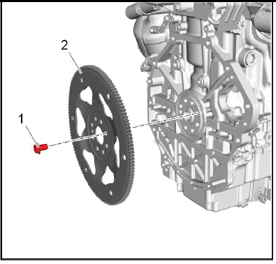
2.
To prevent crankshaft rotation, install the EN-50792 holding tool (2) and starter motor bolts (1) at the starter motor location and engaging the automatic flex plate.
3.
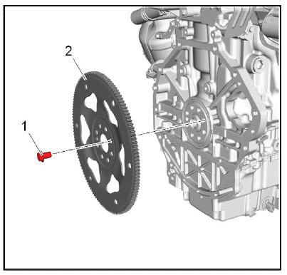
Automatic Transmission Flex Plate Bolt (1) - Remove and DISCARD [8x].
4. Automatic Transmission Flex Plate (2) - Remove.
5. Remove the special tool: EN-50792 holding tool.
Installation Procedure
1.
CAUTION: This vehicle is equipped with torque-to-yield or single use fasteners. Install a NEW torque-to-yield or single use fastener when installing this component.
Failure to replace the torque-to-yield or single use fastener could cause damage to the vehicle or component.
NOTE: Fasteners have adhesive patch and must be tightened to final torque within 5 minutes.
Automatic Transmission Flex Plate (2) - Install.
2. Automatic Transmission Flex Plate Bolt (1) - Install NEW [8x].
3.
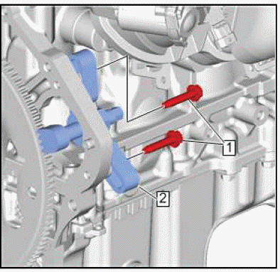
To prevent crankshaft rotation, install EN-50792 holding tool (2) and starter motor bolts (1) at the starter motor location and engaging the flex plate.
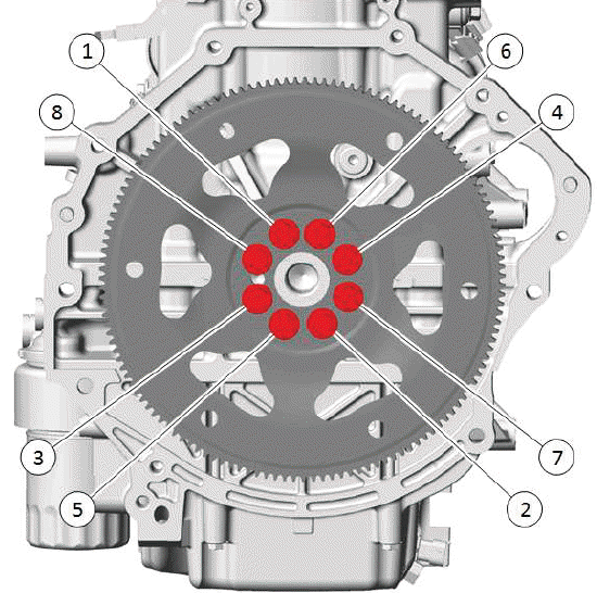
Fig. 10: Flywheel Flex Plate Bolts Tightening Sequence
4.
CAUTION: Fastener Caution.
Tighten in the sequence shown.
- First Pass: 30N.m (22 lb ft)
- Final Pass: 40 degrees - Use the special tool: EN 45059 meter
5. Remove the special tool: EN-50792 holding tool.
6. Transmission - Install.
CRANKSHAFT REAR OIL SEAL REPLACEMENT
Special Tools
EN-51380 Seal Installer
For equivalent regional tools, refer to Special Tools.
Removal Procedure
1. Remove the automatic transmission flex plate. Refer to Automatic Transmission Flex Plate Replacement.
2.
NOTE: Do not damage the outside diameter of the crankshaft or chamber with any tool.
Use a suitable tool to remove the crankshaft rear oil seal (1).
Installation Procedure
1. Using the (2) EN-51380 seal installer, install a NEW crankshaft real oil seal (1).
2. Install the automatic transmission flex plate. Refer to Automatic Transmission Flex Plate Replacement.
Engine Replacement
Removal Procedure
1. Upper Intermediate Steering Shaft - Remove.
2. Recover the refrigerant. Refrigerant Recovery and Recharging (R-1234yf).
3. Drain the coolant. Cooling System Draining and Filling (Static) Cooling System Draining and Filling (GE 47716).
4. Engine Control Module - Remove.
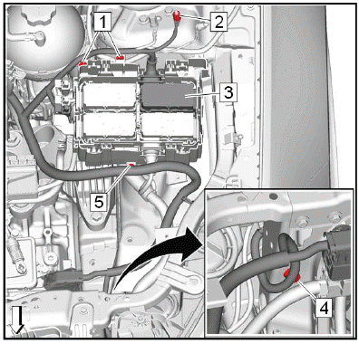
5.
Retaining Tab (2) - Unclip [2x].
6. Battery Distribution Fuse Block Cover (1) - Remove.
7.
Retainer (2) - Unclip.
8. Battery Positive Cable Nut (1) - Remove.
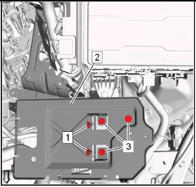
9.
Battery Hold Down Retainer Nut (1) - Remove.
10. Battery Hold Down Bolt (2, 4) - Remove [2x].
11. Battery Hold Down Retainer (6) - Remove.
12. Wiring Harness Retainer (3) - Unclip.
13. Disconnect the electrical connector. (5)
14.
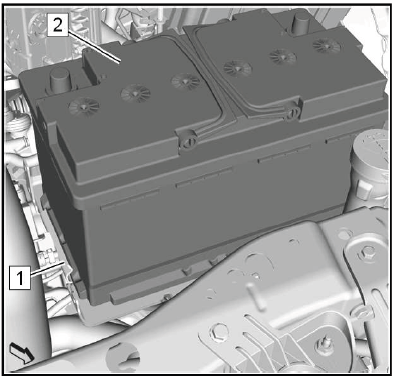
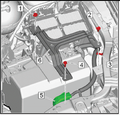
Remove the battery. (2) Battery Replacement (2.0L LTG) 15.
Remove the battery tray. (2) Battery Tray Replacement.
16. Engine Wiring Harness Junction Block - Remove.
17.
Ground Cable Nut (2) - Remove.
18. Wiring Harness Retainer (1, 4, 5) - Remove [4x].
19. Electrical Connector (3) - Unclip.
20.
Ground Cable Bolt (1) - Remove.
21.
Disconnect the electrical connector. (1)
22.
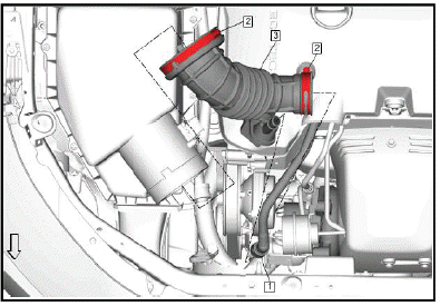
NOTE: The Positive Crankcase Ventilation (PCV) tube has a tamper-proof fitting and cannot be disconnected without damage to the PCV tube. Only disconnect the PCV tube if replacing the air cleaner outlet duct. If repositioning the air cleaner outlet duct, leave the PCV tube connected.
Air Cleaner Outlet Duct (3) - Remove.
23.
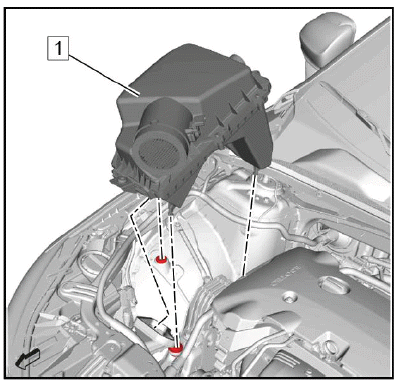
Air Cleaner Assembly (1) - Remove.
24.
Engine Coolant Air Bleed Hose (3) - Remove.
25. Fuel Feed Front Pipe - Remove.
26.
Evaporative Emission Front Pipe (2) @ Evaporative Emission Canister Purge Solenoid Valve (1) - Disconnect.
27. Close all connections with EN-6015 plugs.
28.
Electrical Connector (1) @ Intake Air Pressure and Temperature Sensor (2) - Disconnect.
29.
Charge Air Cooler Outlet Air Tube Fastener (1) - Remove.
30. Retainer Spring (2) - Release.
31. Charge Air Cooler Outlet Air Tube (3) - Disconnect.
32.
Range Selector Lever Cable (1) @ Range Selector Lever Cable Lever (4) - Remove - Use a suitable tool.
33. Range Selector Lever Cable (1) @ Transmission Range Selector Lever Cable Bracket (2) - Remove.
Push the lashes (3) in direction of arrow to release the range selector lever cable from the bracket.
34.
Power Brake Booster Vacuum Pipe (1) - Disconnect.
35.
Clamp (2, 4, 7) - Remove [3x].
36. Radiator Inlet Hose (1) @ Water Outlet (3) - Disconnect.
37. Heater Inlet Hose (5) @ Water Outlet (3) - Disconnect.
38. Heater Outlet Hose (6) @ Water Outlet (3) - Disconnect.
39.
Clamp (1) - Remove.
40. Radiator Outlet Hose (2) - Disconnect.
41.
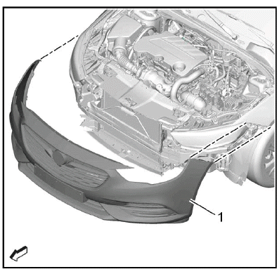
Front Bumper Fascia (1) - Remove.
42.
Ground Cable Nut (1) - Remove.
43. Ground Cable (2) - Remove.
44.
Charge Air Cooler Inlet Air Tube Bolt (1) - Remove.
45. Warm Up Three-Way Catalytic Converter - Remove.
46.
Retainer Spring (2) - Release.
47. Charge Air Cooler Inlet Air Tube (1) - Disconnect.
48.
Charge Air Cooler Inlet Air Tube Bolt (2) - Remove.
49. Charge Air Cooler Inlet Air Tube (3) - Remove.
50. Remove and DISCARD the gasket. (1)
51.
Retainer Spring (1) - Release.
52. Charge Air Cooler Outlet Air Tube (2) - Remove.
53.
Air Conditioning Compressor and Condenser Hose Bolt (1) - Remove.
54. Air Conditioning Compressor and Condenser Hose (2) - Remove.
55. Seal Ring (3) - Remove and DISCARD [2x].
56. Remove the front tire and wheel assemblies.
57.
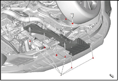
Front Compartment Splash Shield (4) - Remove.
58.
Front Compartment Air Deflector (4) - Remove.
59.
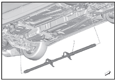
Propeller Shaft (1) - Remove.
60.
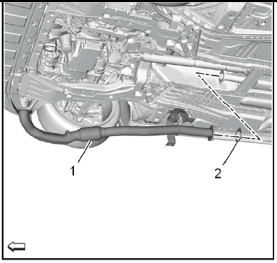
Exhaust Front Pipe (1) - Remove.
61.
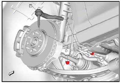
Steering Linkage Outer Tie Rod (3) @ Steering Knuckle - Separate [2x].
62.
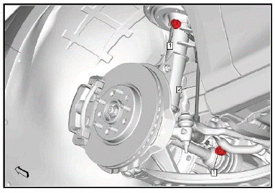
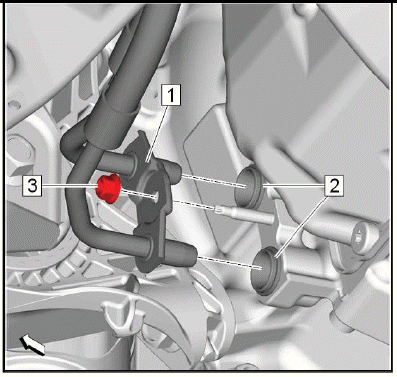
Stabilizer Shaft Link (2) @ Stabilizer Shaft - Separate [2x].
63.
{ If equipped }Front Suspension Automatic Forward Lighting Position Sensor (1) @ Lower Control Arm - Separate [2x].
64.
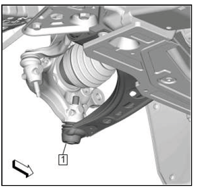
Lower Control Arm (1) @ Steering Knuckle - Separate [2x].
65. Drain the transmission fluid.
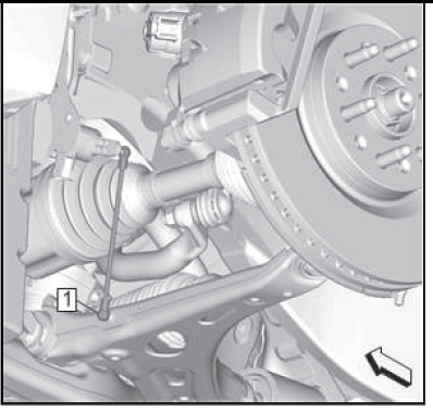
66. Power Transfer Unit Case - Remove.
67. Front Wheel Drive Half Shaft - Left Side @ Front Wheel Bearing - Remove.
68.
Transmission Fluid Cooler Inlet and Outlet Pipe Nut (3) - Remove.
69. Transmission Fluid Cooler Inlet and Outlet Pipe (1) - Remove.
70. Plug and / or cap the hose and transmission to prevent contamination.
71.
Engine Mount Bolt (1) - Remove and DISCARD [2x].
72.
Remove and DISCARD the 4 transmission mount transmission side bolts (1).
73.
Front Cradle Brace-Both Sides - Remove - Front Cradle Brace Replacement.
74.
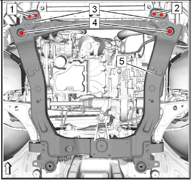
NOTE: A second technician is required.
Simplified graphic. Engine/transmission unit is fixed with engine support tool to suspension frame. Suspension frame is supported by centering frame and base frame.
Front Cradle Brace Bolt (1, 2) - Remove [4x].
75. Drivetrain and Front Suspension Cradle Front Bolt (4) - Remove [2x].
76. Front Cradle Mount Bolt Bracket (3) - Remove [2x].
77. Carefully lower the engine table and raise the body on the hoist until the engine/transmission and frame are separated from the vehicle.
Disassemble Procedure
1. Front Wheel Drive Half Shaft-Left Side - Remove.
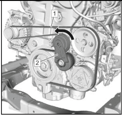
2.
Tension the drive belt tensioner (2) in arrow direction and hold tension.
NOTE: A second technician is required.
3. Drive Belt (1) - Remove.
4. Slowly release the tension on the drive belt tensioner (2).
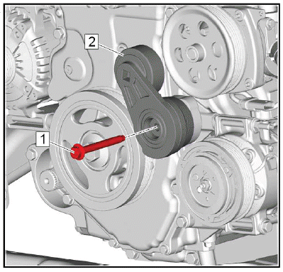
5.
Drive Belt Tensioner Bolt (1) - Remove.
6. Drive Belt Tensioner (2) - Remove.
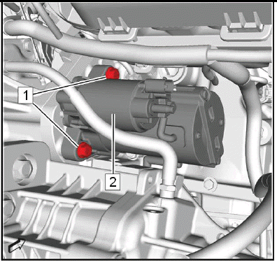
7. Battery Positive Cable - Remove.
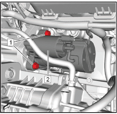
Starter (2) - Remove.
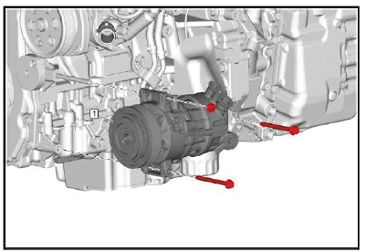
9.
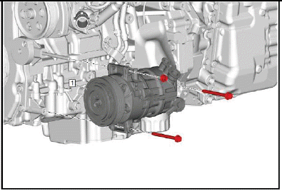
Air Conditioning Compressor (1) - Remove.
10.
Generator (1) - Remove.
11.
Engine Wiring Harness (1) - Remove.
12. Install a suitable cable to the 3 engine lift brackets.
13. Install a suitable engine lifting device to the cable.
14. Extend the engine lifting device until the steel cables are slightly tensioned.
15.

Remove and DISCARD the transmission front mount bolt (1).
16. Put the engine transmission unit down on a wooden pallet.
17.
Torque Converter @ Flex Plate - Loosen
- Turn the engine at the crankshaft balancer clockwise with a suitable tool, until a torque converter bolt (1) shows up.
- Remove and DISCARD the first torque converter bolt.
- Turn the engine at the crankshaft balancer clockwise 60 degrees.
- Remove and DISCARD the second torque converter bolt.
- Repeat the previous 4 steps for the third torque converter bolt.
18.
Transmission Bolt (1) - Remove [2x].
19.
Pump and Component Oil Heat Shield Bolt (2) - Remove [2x].
20. Remove the oil pump flow control valve heat shield bolt (3).
21. Oil Pump Flow Control Valve Heat Shield (1) - Remove.
22.
Transmission Bolt (1, 2) - Remove [3x].
23.
Transmission Bolt (1) - Remove [3x].
24. Wiring Harness Bracket (2) - Remove.
25.
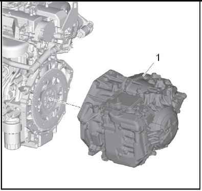
NOTE: A second technician is required.
Transmission (1) - Remove.
26. Install the engine to a suitable engine stand.
27. Transfer components as necessary.
Assemble Procedure
1. Remove the engine from the engine stand.
2. Put the engine down on a wooden pallet.
3.
NOTE: A second technician is required.
Transmission (1) - Install.
4.
CAUTION: Fastener Caution.
Wiring Harness Bracket (2) - Install.
5. Transmission Bolt (1) - Install and tighten [3x]58N.m (43 lb ft).
6.

Transmission Bolt (1, 2) - Install and tighten [3x]58N.m (43 lb ft).
7.
Oil Pump Flow Control Valve Heat Shield (1) - Install.
8. Install the oil pump flow control valve heat shield bolt (3) and tighten to 58N.m (43 lb ft).
9. Pump and Component Oil Heat Shield Bolt (2) - Install and tighten [2x]9N.m (80 lb in).
10.
Transmission Bolt (1) - Remove [2x]58N.m (43 lb ft).
11.
Torque Converter @ Flex Plate - Install.
- Turn the engine at the crankshaft balance clockwise with a suitable tool, until a torque converter bolt (1) shows up.
NOTE: Service may offer bolts without microencapsulated thread locking adhesive. If this is the case, apply thread locking adhesive to the bolt.
If fasteners are microencapsulated, install NEW torque converter to flexplate bolts. Do NOT reuse the old bolts.
- Install the first NEW torque converter bolt (1) and tighten to 60N.m (44 lb ft).
- Turn the engine at the crankshaft balancer clockwise 60 degrees.
- Install the second NEW torque converter bolt and tighten to 60N.m (44 lb ft).
- Repeat the previous 4 steps for the third torque converter bolt.
12. Place the engine transmission unit to the suspension frame.
13.
Install the NEW transmission front mount bolt and tighten to 100N.m (74 lb ft).
14. Remove the engine lifting device and the cable from the engine.
15.
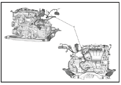
Engine Wiring Harness (1) - Install.
16.
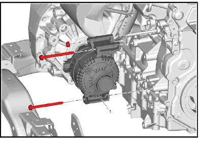
Generator (1) - Install - Generator Replacement (2.0L LTG).
17.
Air Conditioning Compressor (1) - Install.
18.
Starter (2) - Install.
19. Battery Positive Cable - Install.
20.
Drive Belt Tensioner (1) - Install.
21. Drive Belt Tensioner Bolt (2) - Install and tighten58N.m (43 lb ft).
22.
Tension the drive belt tensioner (2) in arrow direction and hold tension.
NOTE: A second technician is required.
23. Drive Belt (1) - Remove.
24. Slowly release the tension on the drive belt tensioner (2).
25. Front Wheel Drive Half Shaft @ Transmission - Install.
Installation Procedure
1.
NOTE:
- A second technician is required.
- Simplified graphic. Engine/transmission unit is fixed with engine support tool to suspension frame. Suspension frame is supported by centering frame and base frame.
- During the tightening procedure check that the pins (7) slide easily in their holes.
Raise the drivetrain and front suspension frame (5) and install it with the engine transmission to the vehicle.
2. Front Cradle Mount Bolt Bracket (3) - Install [2x].
3. Drivetrain and Front Suspension Cradle Front Bolt (4) - Install and hand tighten [2x].
4. Front Cradle Brace Bolt (1, 2) - Install and hand tighten [4x].
5. Front Cradle Brace (9) - Install [2x].
6. Drivetrain and Front Suspension Cradle Rear Bolt (8) - Install and hand tighten [2x].
7. Front Cradle Brace Bolt (6, 10, 11) - Install and hand tighten [4x].
8. Install the 2 CH - 51034 pins (7) to arrange the front suspension frame during tightening.
9. Make sure that the drivetrain and front suspension frame (5) fits closely to the vehicle.
10. Make sure that the 2 CH - 51034 pins (7) fit closely to the drivetrain and front suspension frame (5).
11. Drivetrain and Front Suspension Cradle Front Bolt (4) - Tighten [2x]160N.m (118 lb ft).
12. Drivetrain and Front Suspension Cradle Rear Bolt (8) - Tighten [2x]160N.m (118 lb ft).
13. Front Cradle Brace Bolt (1, 2) - Tighten [4x]58N.m (43 lb ft).
14. Front Cradle Brace Bolt (6, 10, 11) - Tighten [4x]58N.m (43 lb ft).
15. Remove the 2 CH - 51034 pins (7) to arrange the front suspension frame during tightening.
16. Lower the vehicle.
17.
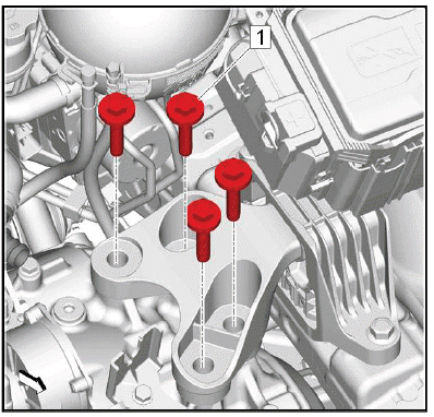
CAUTION: Torque-to-Yield Fastener Caution
Transmission Mount Bolt (1) - Install and tighten the NEW bolt. [4x]
- First Pass: 100N.m (74 lb ft)
- Final Pass: 60 - 75 degrees - Use the special tool: EN-45059 Angle Meter
18.
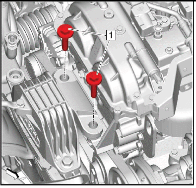
CAUTION: Torque-to-Yield Fastener Caution.
Engine Mount Bolt (1) - Install and tighten the NEW bolt. [2x].
- First Pass: 100N.m (74 lb ft).
- Final Pass: 60 - 75 degrees - Use the special tool: EN-45059 Angle Meter
19. Raise the vehicle.
20. Remove the plugs and / or caps from the hose and transmission.
21.
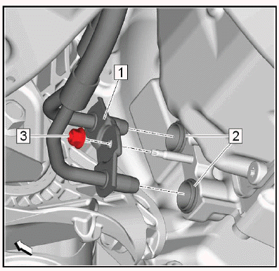
Transmission Fluid Cooler Inlet and Outlet Pipe (1) - Install.
22. Transmission Fluid Cooler Inlet and Outlet Pipe Nut (3) - Install and tighten10N.m (89 lb in).
23. Power Transfer Unit Case - Install.
24. Front Wheel Drive Half Shaft - Left Side @ Front Wheel Bearing - Install.
25.
.png)
Lower Control Arm (1) @ Steering Knuckle - Install [2x].
26.
.png)
{ If equipped }Front Suspension Automatic Forward Lighting Position Sensor (1) @ Lower Control Arm - Install [2x].
27.
.png)
Stabilizer Shaft Link (2) @ Stabilizer Shaft - Install [2x].
28.
.png)
Steering Linkage Outer Tie Rod (3) @ Steering Knuckle - Install [2x].
29.
.png)
Exhaust Front Pipe (1) - Install.
30.
.png)
Propeller Shaft (1) - Install.
31.
.png)
Front Compartment Air Deflector (4) - Install.
32.
.png)
Front Compartment Splash Shield (4) - Install.
33. Tires @ Front - Install.
34.
.png)
Seal Ring (3) - Install NEW [2x].
35. Air Conditioning Compressor and Condenser Hose (2) - Install.
36. Air Conditioning Compressor and Condenser Hose Bolt (1) - Install and tighten19N.m (14 lb ft).
37.
.png)
Install a NEW gasket. (2)
38. Install the 2 charge air cooler inlet air tube bolts (3) to the charge air cooler inlet air tube (1) until they snap to the gasket.
39.
.png)
Charge Air Cooler Inlet Air Tube (1) - Install.
40. Charge Air Cooler Inlet Air Tube Bolt (2) - Install and hand tighten.
41.
.png)
Charge Air Cooler Outlet Air Tube (2) - Install.
42. Lower the vehicle.
43.
.png)
Charge Air Cooler Inlet Air Tube Bolt (1) - Install and tighten22N.m (16 lb ft).
44. Raise the vehicle.
45.
.png)
Charge Air Cooler Inlet Air Tube Bolt (2) - Tighten22N.m (16 lb ft).
46.
.png)
Charge Air Cooler Inlet Air Tube (1) - Connect.
47. Retainer Spring (2) - Engage.
48. Warm Up Three-Way Catalytic Converter - Install.
49. Lower the vehicle.
50.
.png)
Ground Cable (2) - Install.
51. Ground Cable Nut (1) - Install and tighten 9N.m (80 lb in).
52.
.png)
Front Bumper Fascia (1) - Install.
53.
.png)
Radiator Outlet Hose (2) - Connect.
54. Clamp (1) - Install.
55.
.png)
Heater Outlet Hose (6) @ Water Outlet (3) - Connect.
56. Heater Inlet Hose (5) @ Water Outlet (3) - Connect.
57. Radiator Inlet Hose (1) @ Water Outlet (3) - Connect.
58. Clamp (2, 4, 7) - Install [3x].
59.
.png)
Power Brake Booster Vacuum Pipe (1) - Connect.
60. Transmission Fluid - Fill.
61.
.png)
Range Selector Lever Cable (1) @ Transmission Range Selector Lever Cable Bracket (2) - Install.
Push the range selector lever cable into the bracket.
62. Range Selector Lever Cable (1) @ Range Selector Lever Cable Lever (4) - Install - Use a suitable tool.
63.
.png)
Charge Air Cooler Outlet Air Tube (3) - Connect.
64. Retainer Spring (2) - Install.
65. Charge Air Cooler Outlet Air Tube Fastener (1) - Install and tighten 22N.m (16 lb ft).
66.
.png)
Electrical Connector (1) @ Intake Air Pressure and Temperature Sensor (2) - Connect.
67.
.png)
Remove the EN-6015 plugs from all connections.
68. Evaporative Emission Front Pipe (2) @ Evaporative Emission Canister Purge Solenoid Valve (1).
69. Fuel Feed Front Pipe - Install.
70.
.png)
Engine Coolant Air Bleed Hose (3) - Install.
71.
.png)
Air Cleaner Assembly (1) - Install.
72.
.png)
NOTE: The Positive Crankcase Ventilation (PCV) tube has a tamper-proof fitting and cannot be disconnected without damage to the PCV tube. Only disconnect the PCV tube if replacing the air cleaner outlet duct. If repositioning the air cleaner outlet duct, leave the PCV tube connected.
Air Cleaner Outlet Duct (3) - Install - Air Cleaner Outlet Duct Replacement.
73.
.png)
Connect the electrical connector. (1)
74.
.png)
Ground Cable Bolt (1) - Install and tighten9N.m (80 lb in).
75.
.png)
Electrical Connector (3) - Install.
76. Wiring Harness Retainer (1, 4, 5) - Install [4x].
77. Ground Cable Nut (2) - Install and tighten 9N.m (80 lb in).
78. Engine Wiring Harness Junction Block - Install.
79.
.png)
Install the battery tray. (2) Battery Tray Replacement.
80.
.png)
Install the battery. (2) Battery Replacement (2.0L LTG).
81.
.png)
Connect the electrical connector. (5)
82. Wiring Harness Retainer (3) - Install.
83. Battery Hold Down Retainer (6) - Install.
84. Battery Hold Down Bolt (2, 4) - Install and tighten [2x] 9N.m (80 lb in).
85. Battery Hold Down Retainer Nut (1) - Install and tighten 9N.m (80 lb in).
86.
.png)
Battery Positive Cable Nut (1) - Install and tighten16N.m (12 lb ft).
87. Retainer (2) - Install.
88.
.png)
Battery Distribution Fuse Block Cover (1) - Install.
89. Retaining Tab (2) - Install [2x].
90. Recharge the refrigerant.
91. Coolant - Fill.
92. Engine Oil - Fill.
93. Upper Intermediate Steering Shaft - Install.
94. Perform the crankshaft position variation learn.
Engine Oil and Oil Filter Replacement
Removal Procedure
1. Raise and support the vehicle.
2. Place a drain pan under the vehicle.
3.
.png)
Oil Pan Drain Plug (1) - Remove.
4. Oil Pan Drain Plug Seal (2) - Remove and DISCARD.
5. Drain the engine oil into a suitable container.
6.
.png)
Remove and DISCARD the oil filter. (1)
7. Ensure that the old oil filter seal has been removed.
Installation Procedure
1.
.png)
CAUTION: Fastener Caution.
Oil Pan Drain Plug Seal (2) - Install NEW.
2. Oil Pan Drain Plug (1) - Install and tighten 25N.m (18 lb ft).
3.
.png)
Lubricate the NEW oil filter gasket with clean engine oil.
4. Install a NEW oil filter and tighten 3/4 to 1 full turn after the gasket makes contact with the sealing surface on the filter mounting flange.
5. Remove the drain pan.
6. Lower the vehicle.
CAUTION: Using engine oils of any viscosity other than those viscosities recommended could result in engine damage.
7. Fill the engine oil to the proper level with NEW engine oil.
8. Start the engine and allow it to run until the oil pressure control indicator goes off.
9. Check and correct the engine oil level.
10. Perform the engine oil life reset.
READ NEXT:
 Repair Instructions - Off Vehicle
Draining Fluids and Oil Filter Removal
1.
Remove the oil filter (1). Remove the oil pan drain plug and allow the oil to
drain out.
2. Clean the oil filter housing in the engine block.
CAUTION: Refe
Description and Operation
Turbocharger System Description
Turbocharger Description and Operation
A turbocharger is a compressor that is used to increase the power output of
an engine by increasing the mass of the
oxygen and t
Special Tools and Equipment
SPECIAL TOOLS
DT-45866
J-45866
Input Shaft Seal Installer
EN-8062
J-8062
KM-348
Valve Spring Compressor - Head Off
EN-8087
J-8087
Cylinder Bore Gauge
EN-21867-850
J-21867-850
KM-498-B
KM-6106
83 93
SEE MORE:
Description and Operation
ELECTRONIC PARKING BRAKE DESCRIPTION
Vehicles with the electric parking brake have a switch in the center console
or on the dash, which takes
the place of the manual parking brake system, the foot pedal and release handle.
In case of insufficient
electrical power, the electric parking brake cannot
Crankshaft & Main Bearings
REMOVAL
NOTE: Examples used in this article are general in nature and do not
necessarily
relate to a specific engine or system. Illustrations and procedures have
been chosen to guide mechanic through engine overhaul process.
Descriptions of processes of cleaning, inspection, assembly and machine
s
