Opel Insignia: Repair Instructions - Off Vehicle
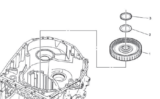
Torque Converter Assembly Removal
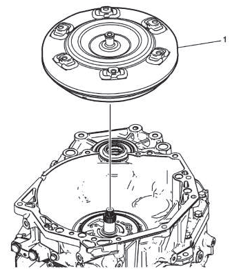
- Torque Converter
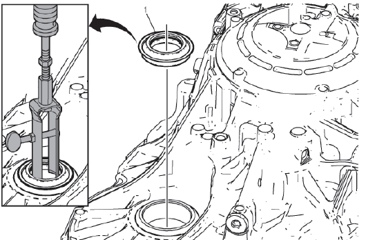
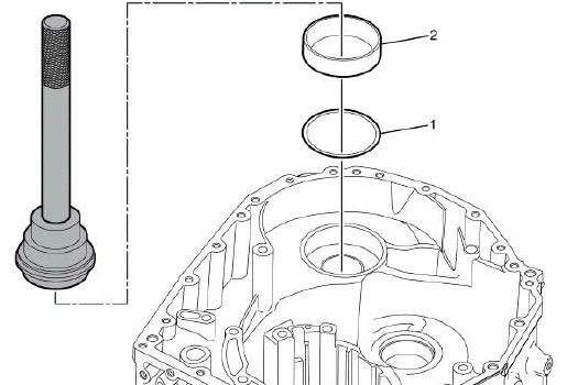
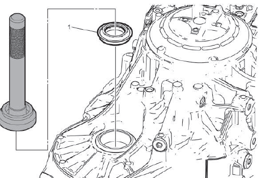
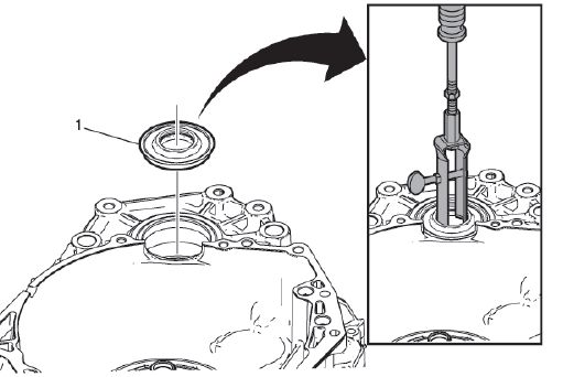
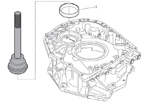
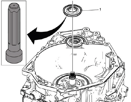
TORQUE CONVERTER FLUID SEAL REMOVAL
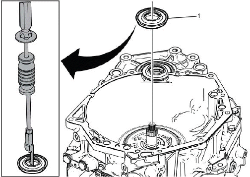
- Torque Converter Fluid Seal
Special Tools
EN-45000 Seal Remover
Equivalent regional tools: Refer to Special Tools
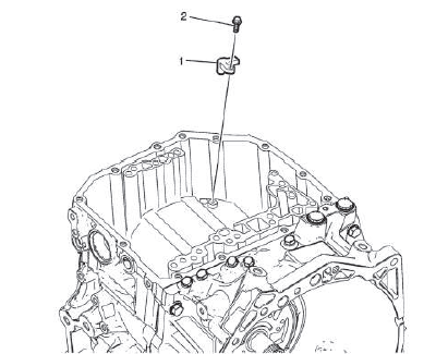
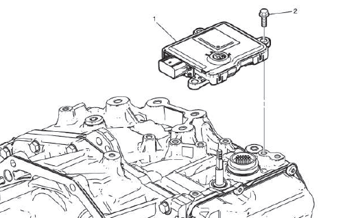
TRANSMISSION CONTROL MODULE REMOVAL
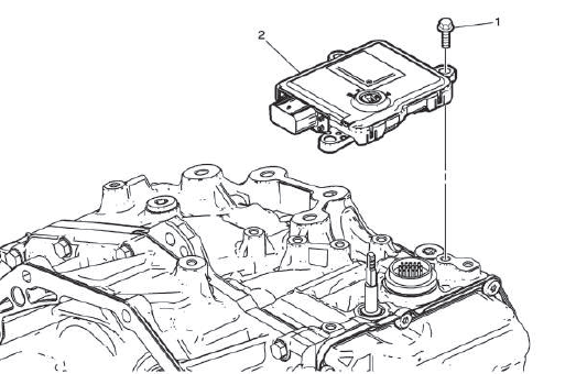
- Transmission Control Module Bolt [3x]
- Transmission Control Module
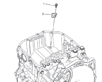
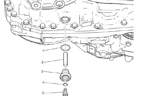
TRANSMISSION FLUID FILLER OVERFLOW TUBE AND DRAIN PLUG REMOVAL
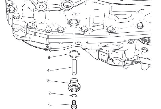
- Transmission Oil Drain Plug
- Transmission Oil Drain Plug Seal
NOTE: Remove and DISCARD the seal.
- Transmission Oil Level Check Plug Seal
- Transmission Fluid Filler Upper Tube
- Transmission Oil Level Check Plug Seal
NOTE: Remove and DISCARD the seal.
CONTROL VALVE BODY COVER REMOVAL
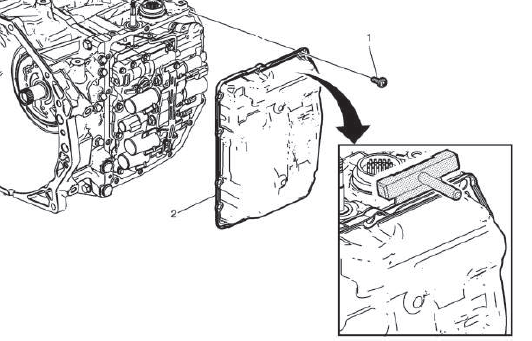
- Control Valve Body Cover Bolt [13x]
- Control Valve Body Cover
Procedure
Carefully slide the DT-37228 seal cutter around the perimeter of the control valve body cover to break the RTV seal.
Special Tools
DT-37228 Seal Cutter
For equivalent regional tools, refer to Special Tools.
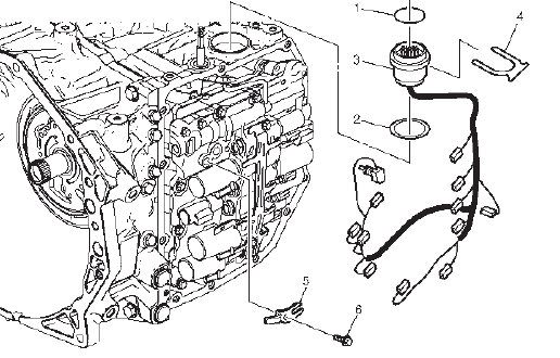
WIRING HARNESS REMOVAL
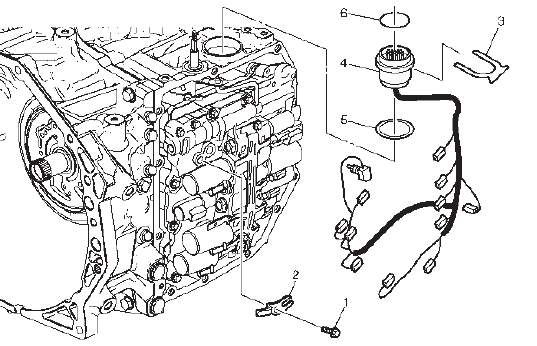
- Automatic Transmission Fluid Temperature Sensor Bolt
- Automatic Transmission Fluid Temperature Sensor Clip
- Automatic Transmission Wiring Harness Retainer
- Wiring Harness Wire
NOTE: Ensure you mark where each connector goes prior to removal.
- Automatic Transmission Wiring Connector Seal
- Automatic Transmission Wiring Connector Seal
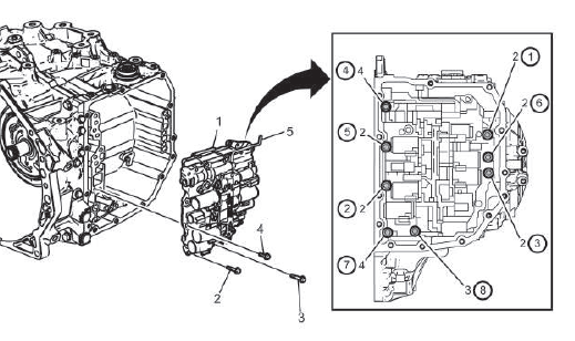
CONTROL VALVE BODY ASSEMBLY REMOVAL
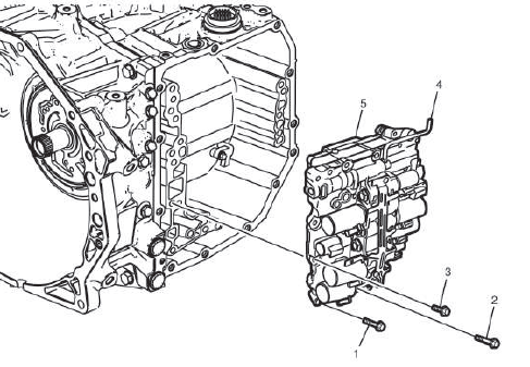
- Valve Body Bolt[2x] M6 x 31
- Valve Body Bolt [1x] M6 x 51
- Valve Body Bolt[5x] M6 x 21
- Manual Valve Link
NOTE: Disconnect the manual valve link, DO NOT remove.
- Control Valve Body - Model Dependent
NOTE: For models with start/stop, Electronic Component Description.
INPUT SPEED SENSOR REMOVAL
- Automatic Transmission Input Speed Sensor Bolt
- Automatic Transmission Input Speed Sensor
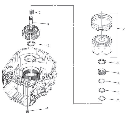
TORQUE CONVERTER AND DIFFERENTIAL HOUSING REMOVAL
- Torque Converter Housing Bolt[5x] M8 x 30
- Torque Converter Housing Bolt[2x] M8 x 35
- Torque Converter Housing Bolt [2x] M10 x 40
- Torque Converter Housing Bolt[14x] M8 x 39
- Torque Converter and Differential Housing
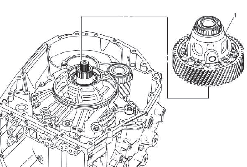
DIFFERENTIAL ASSEMBLY REMOVAL
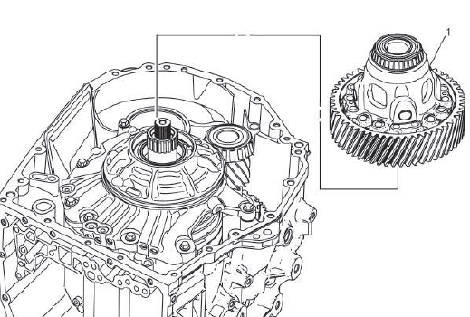
- Differential
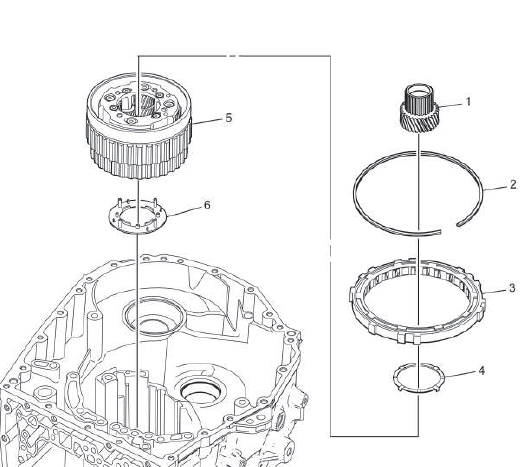
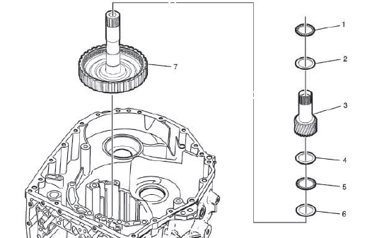
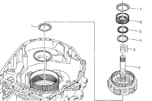
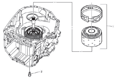
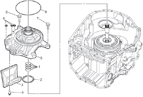
AUTOMATIC TRANSMISSION FLUID PUMP AND FLUID FILTER REMOVAL
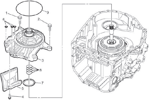
- Automatic Transmission Fluid Pump Bolt [2x]
- Automatic Transmission Fluid Pump Bolt [5x]
- Automatic Transmission Fluid Pump
- Automatic Transmission Fluid Filter Bolt [2x]
- Automatic Transmission Fluid Filter
NOTE: Remove and DISCARD the filter.
- Automatic Transmission Fluid Pump Seal[3x]
NOTE: Remove and DISCARD the seal.
- Automatic Transmission Fluid Pump Shaft Thrust Washer
- Automatic Transmission Fluid Pump Ring[4x]
NOTE: Remove and DISCARD the seal.
- Automatic Transmission Fluid Pump Seal
NOTE: Remove and DISCARD the seal.
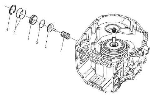
FORWARD BAND SERVO PISTON REMOVAL
- 2-4 Band Servo Cover Retaining Ring
WARNING: Before removing the spring, cover the spring with a towel to prevent the spring from flying and possibly causing damage or personal injury.
NOTE: Remove and DISCARD the retainer.
- 2-4 Band Servo Cover Seal - O-Ring
NOTE: Remove and DISCARD the seal.
- Forward Band Servo Cover
- Forward Clutch Accumulator Piston Fluid Seal Ring
NOTE: Remove and DISCARD the seal.
- Forward Band Servo Piston
- 2nd Clutch Accumulator Piston Spring
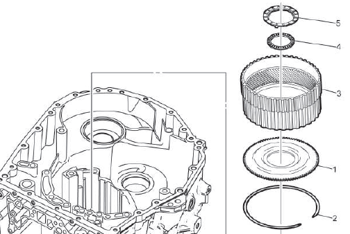
3RD CLUTCH AND FRONT CARRIER REMOVAL
- Automatic Transmission Case Bolt
NOTE: 3rd Clutch Band may be removed without removing automatic transmission case bolt.
- 3rd Clutch
- Automatic Transmission Fluid Pump Shaft Thrust Washer
- Front Sun Gear
- Front Sun Gear Thrust Bearing Race
- Sun Gear Thrust Bearing
- Front Carrier Thrust Bearing Race
- Front Carrier
- Front Carrier Thrust Bearing Race
- Input Shaft Fluid Seal Ring[4x]
NOTE: Install NEW seals. Do NOT reuse old seals.
FRONT INTERNAL GEAR REMOVAL
- Front Carrier Thrust Bearing
- Front Internal Gear
- Forward Clutch Backing Plate Retaining Ring
- Input Carrier Flange
FORWARD CLUTCH ASSEMBLY REMOVAL
- Input Clutch Housing Thrust Bearing
- Forward Clutch Housing Thrust Bearing Race
- Forward Clutch
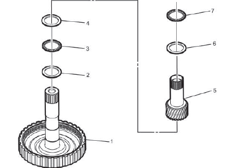
INPUT DRUM REMOVAL
- Input Sun Gear Thrust Bearing
- Sun Gear Front Thrust Bearing Race
- Input Drum
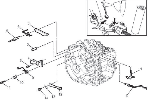
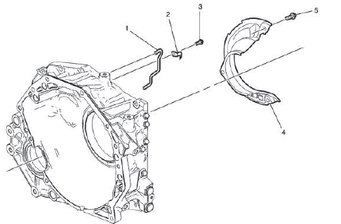
Manual Shift Detent Lever and Park Pawl Removal
Park Components Removal
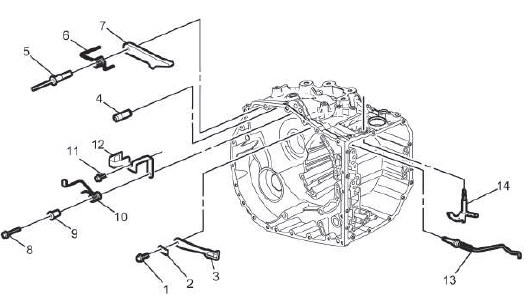
Park Components Removal
- Manual Shift Detent Bolt
- Automatic Transmission Control Lever Detent Spring
- Manual Shift Detent Lever Spring
- Park Pawl Lockout Pin
- Park Pawl Shaft
- Park Pawl Spring
- Park Pawl
- Park Pawl Actuator Bracket Bolt
- Park Pawl Pin Spring Guide Sleeve
- Park Pawl Actuator Lever Spring
- Park Pawl Actuator Bracket Bolt
- Park Pawl Actuator Bracket
- Park Pawl Actuator Rod
- Manual Shift Shaft Lever
Lubricant Fluid Pipe Removal

- Front Differential Transfer Drive Gear Fluid Passage Tube Bolt[2x]
- Automatic Transmission Control Wiring Harness Clamp
- Lubricant Fluid Pipe Retainer
- Lubricant Fluid Pipe
- Torque Converter and Differential Housing Bolt
- Automatic Transmission Vent Baffle Cover
- Torque Converter and Differential Housing Bolt
- Automatic Transmission Vent Baffle Cover
FINAL DRIVE PINION AND RING GEAR REMOVAL
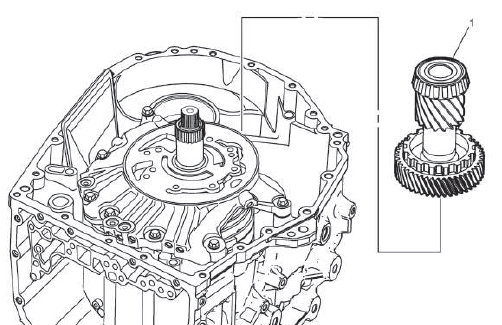
- Final Drive Pinion and Ring Gear
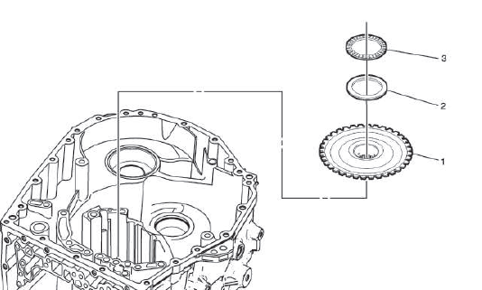
COUNTER DRIVE GEAR REMOVAL
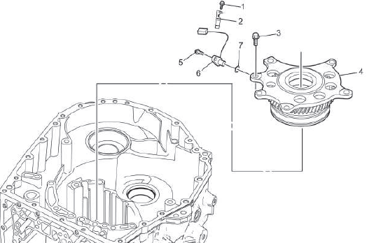
- Front Differential Transfer Drive Gear Fluid Passage Tube Bolt
- Automatic Transmission Control Wiring Harness Clamp
NOTE: It may be necessary to remove the automatic transmission control wiring harness clamp to access all the bolts.
- Center Support Bolt [6x]
- Counter Drive Gear
- Automatic Transmission Intermediate Speed Sensor Bolt
- Vehicle Speed Sensor
- Vehicle Speed Sensor Spacer
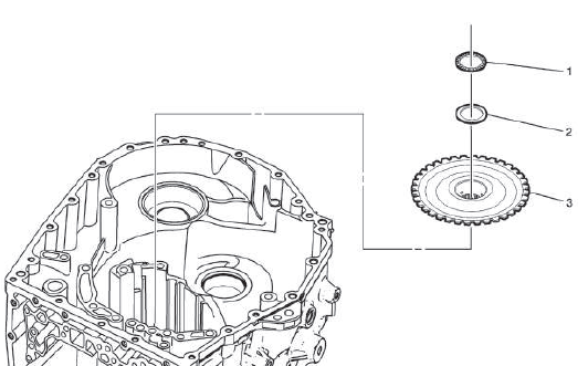
OVERRUN CLUTCH AND REAR CARRIER REMOVAL
- Sun Gear
- Overrun Clutch Retaining Ring
- Overrun Clutch
- Rear Carrier Thrust Washer
- Rear Carrier
- Rear Carrier Thrust Washer
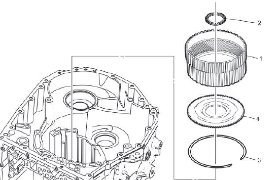
1ST AND REVERSE CLUTCH BACKING PLATE REMOVAL
- 1-Reverse Clutch Backing Plate Retaining Ring
- Forward Clutch Backing Plate
- 1st and Reverse Clutch Plate - Friction Plate
- 1st and Reverse Clutch Plate
- 1st and Reverse Clutch Backing Plate
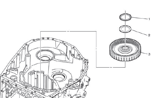
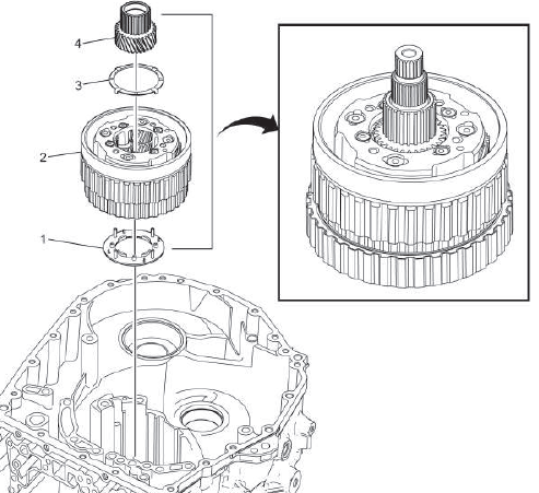
DIRECT CLUTCH ASSEMBLY REMOVAL
- Rear Sun Gear Thrust Bearing
- Rear Sun Gear Thrust Bearing Race
- Rear Sun Gear
- Rear Sun Gear Thrust Bearing Race
- Direct Clutch Bearing
- Direct Clutch Hub Thrust Bearing Race
- Direct Clutch
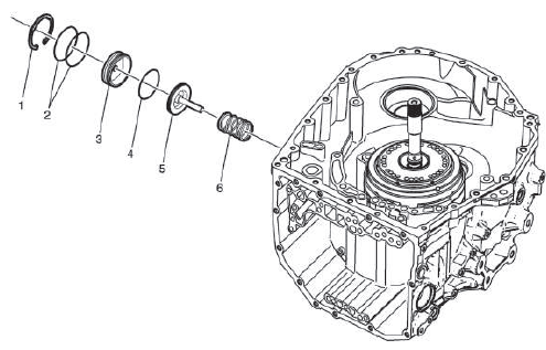
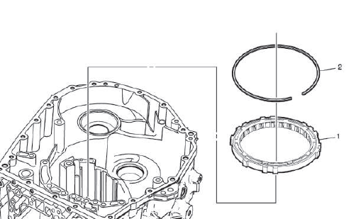
LOW AND REVERSE CLUTCH PISTON REMOVAL
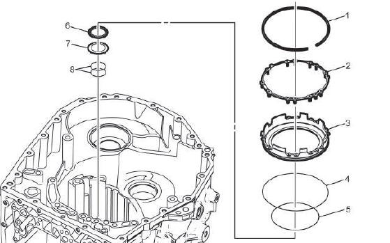
- 1-Reverse Clutch Spring Retaining Ring
- 1-Reverse Clutch Spring
- Low and Reverse Clutch Piston
Procedure
Apply compressed air to the case passage to remove the low and reverse clutch piston.
- Low and Reverse Clutch Application Ring
- Low and Reverse Clutch Application Ring
- 2nd Clutch Housing Rear Bearing
- Direct Clutch Hub Thrust Bearing Race
- Direct Clutch Fluid Seal Ring [2x]
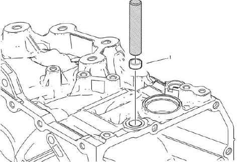
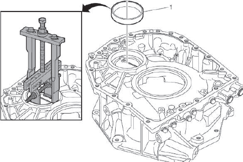
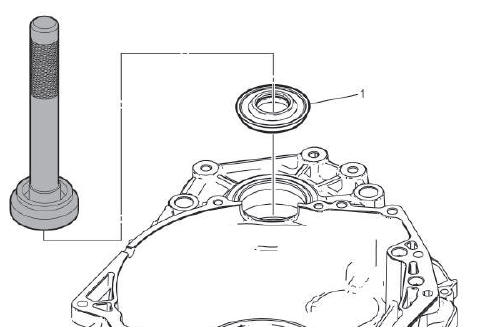
MANUAL SHIFT SHAFT SEAL REMOVAL
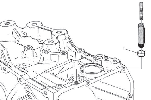
- Manual Shift Shaft Seal
Special Tools
DT-43911 Selector Shaft Seal Remover
For equivalent regional tools, refer to Special Tools.
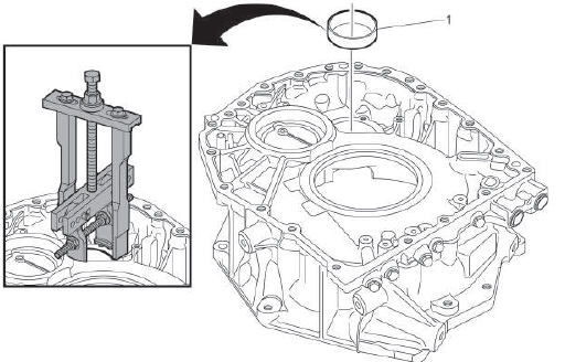
FRONT WHEEL DRIVE SHAFT OIL SEAL REMOVAL - RIGHT SIDE
- Front Wheel Drive Shaft Oil Seal - Right Side
Special Tools
- DT-26941 Remover
- GE-6125-1B Slide Hammer with Adapter
For equivalent regional tools, refer to Special Tools.
DIFFERENTIAL BEARING RACE REMOVAL
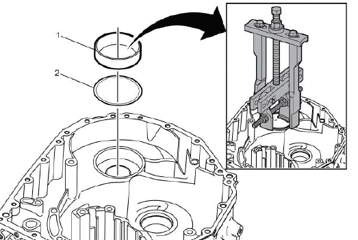
- Differential Bearing Race
Special Tools
- DT-45124 Removal Bridge
- DT-45124-9 Puller Leg
- DT-51919 Bearing Race Remover
Equivalent regional tools: Refer to Special Tools.
COUNTER GEAR THRUST BEARING RACE REMOVAL
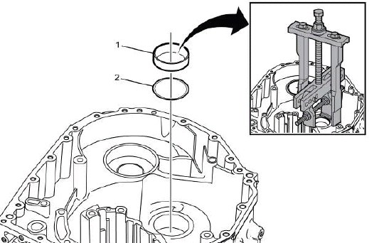
- Counter Gear Thrust Bearing Race
Special Tools
- DT-45124 Removal Bridge
- DT-45124-9 Puller Leg
- DT-51919 Bearing Race Remover
Equivalent regional tools: Refer to Special Tools
COUNTER GEAR THRUST BEARING RACE INSTALLATION
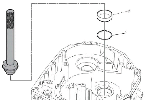
- Counter Gear Thrust Bearing Race
Special Tools
- DT-51918 Bearing Race Installer
- GE-8092 Driver Handle
For equivalent regional tools, refer to Special Tools.
DIFFERENTIAL BEARING RACE INSTALLATION
- Differential Bearing Race
Special Tools
- DT-51918 Bearing Race Installer
- GE-8092 Driver Handle
For equivalent regional tools, refer to Special Tools.
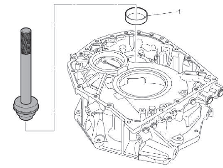
FRONT WHEEL DRIVE SHAFT OIL SEAL INSTALLATION - RIGHT SIDE
- Front Wheel Drive Shaft Oil Seal - Right Side
Special Tools
- DT-50298 Axle Seal Installer
- GE-8092 Driver Handle
For equivalent regional tools, refer to Special Tools.
MANUAL SHIFT SHAFT SEAL INSTALLATION
- Manual Shift Shaft Seal
Special Tools
DT-49101 Seal Installer
For equivalent regional tools, refer to Special Tools.
Low and Reverse Clutch Piston Installation
- Direct Clutch Fluid Seal Ring [2x]
- Direct Clutch Hub Thrust Bearing Race
- 2nd Clutch Housing Rear Bearing
- Low and Reverse Clutch Application Ring
- Low and Reverse Clutch Application Ring
- Low and Reverse Clutch Piston
- 1-Reverse Clutch Spring
- 1-Reverse Clutch Spring Retaining Ring
Procedure
Using the DT-48056 bridge with DT-48903 and DT-51920 compressors, install the retaining ring.
NOTE: Ensure DT-51920 Clutch Spring Compressor is clocked properly and only making contact with the 1-Reverse clutch spring.
Special Tools
- DT-48056 Spring Compressor Bridge
- DT-48903 Spring Compressor
- DT-51920 Clutch Spring Compressor
Equivalent regional tools: Refer to Special Tools
DIRECT CLUTCH ASSEMBLY INSTALLATION
- Direct Clutch
- Direct Clutch Hub Thrust Bearing Race
- Direct Clutch Bearing
- Rear Sun Gear Thrust Bearing Race
- Rear Sun Gear
- Rear Sun Gear Thrust Bearing Race
- Rear Sun Gear Thrust Bearing
REAR CARRIER INSTALLATION
- Rear Carrier Thrust Washer
- Rear Carrier
Procedure
- Assemble this on the table with Direct Clutch Assembly Installation.
- Rotate till seated completely.
- Install complete direct clutch and rear carrier assembly as a unit.
- Rear Carrier Thrust Washer
- Sun Gear
1ST AND REVERSE CLUTCH BACKING PLATE INSTALLATION
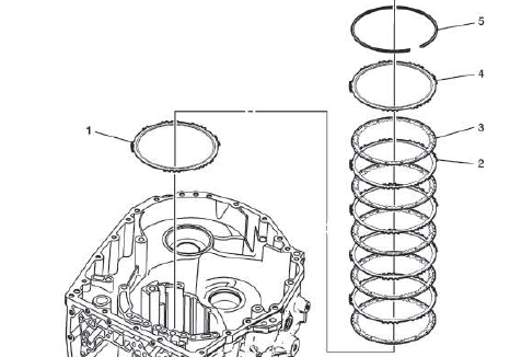
- 1st and Reverse Clutch Backing Plate
NOTE: Machined side down.
- 1st and Reverse Clutch Plate
- 1st and Reverse Clutch Plate - Friction Plate
- Forward Clutch Backing Plate
NOTE: Groove up to accept the retaining ring.
- 1-Reverse Clutch Backing Plate Retaining Ring
OVERRUN CLUTCH INSTALLATION
- Overrun Clutch
NOTE: Rotate the rear carrier clockwise while installing.
- Overrun Clutch Retaining Ring
NOTE: Rotate the rear carrier clockwise until fully seated to accept retaining ring.
COUNTER DRIVE GEAR INSTALLATION
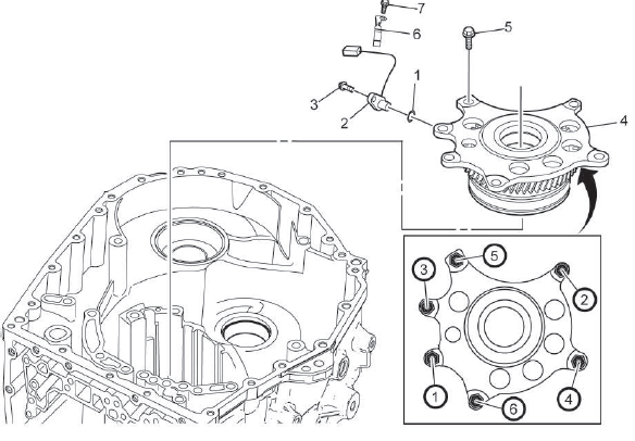
Fig. 3: Automatic Transmission Counter Drive Gear Bolts Tightening Sequence
- Vehicle Speed Sensor Spacer
- Vehicle Speed Sensor
- Automatic Transmission Intermediate Speed Sensor Bolt
CAUTION: Refer to Fastener Caution.
Tighten 5 N.m (44 lb in)
- Counter Drive Gear
- Center Support Bolt[6x]
Tighten in sequence 62 N.m (46 lb ft)
- Automatic Transmission Control Wiring Harness Clamp
- Front Differential Transfer Drive Gear Fluid Passage Tube Bolt
Tighten 7 N.m (62 lb in)
FINAL DRIVE PINION AND RING GEAR INSTALLATION
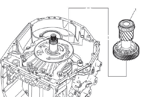
- Final Drive Pinion and Ring Gear
MANUAL SHIFT DETENT LEVER AND PARK PAWL INSTALLATION
Lubricant Fluid Pipe Installation

- Automatic Transmission Vent Baffle Cover
- Torque Converter and Differential Housing Bolt
CAUTION: Refer to Fastener Caution.
Tighten 7 N.m (62 lb in)
- Automatic Transmission Vent Baffle Cover
- Torque Converter and Differential Housing Bolt
Tighten 7 N.m (62 lb in)
- Lubricant Fluid Pipe
- Lubricant Fluid Pipe Retainer
- Automatic Transmission Control Wiring Harness Clamp
- Front Differential Transfer Drive Gear Fluid Passage Tube Bolt [2x]
Tighten 7 N.m (62 lb in)
Park Components Installation
- Manual Shift Shaft Lever
- Park Pawl Actuator Rod
NOTE: Rotate the manual shift shaft lever to get rod in place.
- Park Pawl
- Park Pawl Spring
NOTE: Ensure spring is in proper location like the inset shows.
- Park Pawl Shaft
- Park Pawl Lockout Pin
- Park Pawl Actuator Bracket
NOTE: Ensure park pawl actuator rod is in proper location like the inset shows before tightening the bolts.
- Park Pawl Actuator Bracket Bolt
CAUTION: Refer to Fastener Caution.
Tighten 9 N.m (80 lb in)
- Park Pawl Pin Spring Guide Sleeve
- Park Pawl Actuator Lever Spring
NOTE: Ensure Spring is in proper location like the inset shows.
- Park Pawl Actuator Bracket Bolt
Tighten 9 N.m (80 lb in)
- Manual Shift Detent Lever Spring
- Automatic Transmission Control Lever Detent Spring
- Manual Shift Detent Bolt
Tighten 10 N.m (89 lb in)
INPUT DRUM INSTALLATION
- Input Drum
- Sun Gear Front Thrust Bearing Race
- Input Sun Gear Thrust Bearing
FORWARD CLUTCH ASSEMBLY INSTALLATION
- Forward Clutch
- Forward Clutch Housing Thrust Bearing Race
- Input Clutch Housing Thrust Bearing
Front Internal Gear Installation
- Input Carrier Flange
- Forward Clutch Backing Plate Retaining Ring
- Front Internal Gear
NOTE: Rotate to index the clutch plate and ensure seated.
- Front Carrier Thrust Bearing
- Front Carrier Thrust Bearing Race
FRONT CARRIER INSTALLATION
- Sun Gear Rear Thrust Bearing Race
- Front Carrier
- Input Shaft Fluid Seal Ring[4x]
NOTE: Remove and DISCARD the seal.
- Front Carrier Thrust Bearing Race
- Sun Gear Thrust Bearing
- Front Sun Gear
NOTE: Groove side up.
- Automatic Transmission Fluid Pump Shaft Thrust Washer
3RD CLUTCH INSTALLATION
- 3rd Clutch
NOTE: Line up the fiber plates to help seat, will have to rotate and rock to get to fully seat in place.
- Automatic Transmission Case Bolt (Band Anchor)
CAUTION: Refer to Fastener Caution.
Tighten 167 N.m (123 lb ft)
FORWARD BAND SERVO PISTON INSTALLATION
- 2nd Clutch Accumulator Piston Spring
- Forward Band Servo Piston
NOTE: Pin on the servo piston needs to index on the band.
- Forward Clutch Accumulator Piston Fluid Seal Ring
NOTE: Install a NEW seal. Do NOT reuse the old seal.
- Forward Band Servo Cover
- 2-4 Band Servo Cover Seal (O-ring)
NOTE: Install a NEW seal. Do NOT reuse the old seal.
- 2-4 Band Servo Cover Retaining Ring
NOTE: Install a NEW retaining ring.
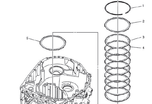
AUTOMATIC TRANSMISSION FLUID PUMP AND FLUID FILTER INSTALLATION
- Automatic Transmission Fluid Pump Ring[4x]
NOTE: Install NEW seals. Do NOT reuse old seals.
- Automatic Transmission Fluid Pump Shaft Thrust Washer
- Automatic Transmission Fluid Filter
NOTE: Install a NEW filter. DO NOT reuse old filter.
- Automatic Transmission Fluid Filter Bolt [2x]
CAUTION: Refer to Fastener Caution.
Tighten 5 N.m (44 lb in)
- Automatic Transmission Fluid Pump
NOTE: Ensure the 3 black seals are on the fluid pump.
- Automatic Transmission Fluid Pump Seal
NOTE: Install a NEW seal. Do NOT reuse the old seal.
- Automatic Transmission Fluid Pump Bolt [5x]
Tighten 25 N.m (18 lb ft)
- Automatic Transmission Fluid Pump Bolt [2x]
Tighten 25 N.m (18 lb ft)
- Automatic Transmission Fluid Pump Seal[3x]
NOTE: Install NEW seals. Do NOT reuse old seals.
DIFFERENTIAL ASSEMBLY INSTALLATION
- Differential
TORQUE CONVERTER AND DIFFERENTIAL HOUSING ASSEMBLY DISASSEMBLE
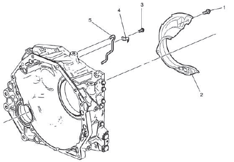
- Automatic Transmission Fluid Baffle Bolt [2x]
- Automatic Transmission Fluid Baffle
- Automatic Transmission Fluid Baffle Bolt
- Lubricant Fluid Hose Clamp
- Front Differential Transfer Drive Gear Fluid Passage Tube
FRONT WHEEL DRIVE SHAFT OIL SEAL REMOVAL - LEFT SIDE
- Front Wheel Drive Shaft Oil Seal - Left Side
Special Tools
- DT-26941 Remover
- GE-6125-1B Slide Hammer with Adapter
For equivalent regional tools, refer to Special Tools.
DIFFERENTIAL DRIVE PINION GEAR OUTER BEARING RACE REMOVAL
- Differential Drive Pinion Gear Outer Bearing Race
Special Tools
- DT-45124 Removal Bridge
- DT-45124-9 Puller Leg
- DT-51919 Bearing Race Remover
Equivalent regional tools: Refer to Special Tools
DIFFERENTIAL CARRIER BEARING RACE REMOVAL
- Differential Carrier Bearing Race
Special Tools
- DT-45124 Removal Bridge
- DT-45124-9 Puller Leg
- DT-51919 Bearing Race Remover
Equivalent regional tools: Refer to Special Tools
DIFFERENTIAL CARRIER BEARING RACE INSTALLATION
- Differential Carrier Bearing Race
Special Tools
- DT-51918 Bearing Race Installer
- GE-8092 Driver Handle
For equivalent regional tools, refer to Special Tools.
DIFFERENTIAL DRIVE PINION GEAR OUTER BEARING RACE INSTALLATION
- Differential Drive Pinion Gear Outer Bearing Race
Special Tools
- DT-51918 Bearing Race Installer
- GE-8092 Driver Handle
For equivalent regional tools, refer to Special Tools.
FRONT WHEEL DRIVE SHAFT OIL SEAL INSTALLATION - LEFT SIDE
- Front Wheel Drive Shaft Oil Seal - Left Side
Special Tools
- DT-52512 Axle Seal Installer
- GE-8092 Driver Handle
For equivalent regional tools, refer to Special Tools.
Torque Converter and Differential Housing Assembly Assemble
- Front Differential Transfer Drive Gear Fluid Passage Tube
- Lubricant Fluid Hose Clamp
- Automatic Transmission Fluid Baffle Bolt
CAUTION: Refer to Fastener Caution.
Tighten 7 N.m (62 lb in)
- Automatic Transmission Fluid Baffle
- Automatic Transmission Fluid Baffle Bolt [2x]
Tighten 7 N.m (62 lb in)
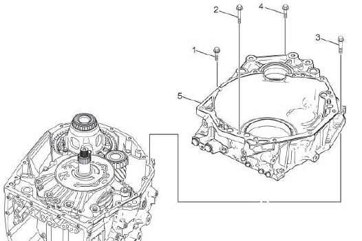
TORQUE CONVERTER AND DIFFERENTIAL HOUSING INSTALLATION
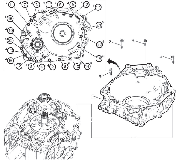
Fig. 4: Torque Converter And Differential Housing Bolts Tightening Sequence
- Torque Converter and Differential Housing
Procedure
Install a bead of sealant around the perimeter of the torque converter and differential housing mating surface: Refer to Adhesives, Fluids, Lubricants, and Sealers.
- Torque Converter Housing Bolt[2x] M10 x 40
CAUTION: Refer to Fastener Caution.
Tighten in sequence 35 N.m (26 lb ft)
- Torque Converter Housing Bolt[2x] M8 x 35
Tighten in sequence 29 N.m (21 lb ft)
- Torque Converter Housing Bolt[14x] M8 x 39
Tighten in sequence 29 N.m (21 lb ft)
- Torque Converter Housing Bolt [5x] M8 x 30
Tighten in sequence 29 N.m (21 lb ft)
INPUT SPEED SENSOR INSTALLATION
- Automatic Transmission Input Speed Sensor
- Automatic Transmission Input Speed Sensor Bolt
CAUTION: Refer to Fastener Caution.
Tighten 5 N.m (44 lb in)
CONTROL VALVE BODY ASSEMBLY INSTALLATION
- Control Valve Body - Model Dependent
NOTE: For models with start/stop, Electronic Component Description.
- Valve Body Bolt [5x] M6 x 21
CAUTION: Refer to Fastener Caution.
Tighten 10 N.m (89 lb in)
- Valve Body Bolt[1x] M6 x 51
Tighten 10 N.m (89 lb in)
- Valve Body Bolt[2x] M6 x 31
Tighten 10 N.m (89 lb in)
- Manual Valve Link
NOTE: Ensure you reconnect the manual valve link.
WIRING HARNESS INSTALLATION
- Automatic Transmission Wiring Connector Seal
- Automatic Transmission Wiring Connector Seal
- Wiring Harness Wire
NOTE: Tab on wiring harness connector fits in slot on case to insure alignment of transmission control module (TCM).
- Automatic Transmission Wiring Harness Retainer
- Automatic Transmission Fluid Temperature Sensor Clip
- Automatic Transmission Fluid Temperature Sensor Bolt
Procedure
Connect the wiring harness connectors to the control valve body in proper location as mark when removed.
Tighten 7 N.m (62 lb in)
CONTROL VALVE BODY COVER INSTALLATION
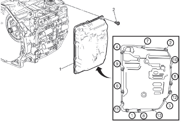
Fig. 5: Automatic Transmission Valve Body Control Unit Cover Bolts Tightening
Sequence
- Control Valve Body Cover
Procedure
Install a bead of sealant around the perimeter of the case to valve body cover mating surface: Refer to Adhesives, Fluids, Lubricants, and Sealers.
- Control Valve Body Cover Bolt [13x]
CAUTION: Refer to Fastener Caution.
Tighten in sequence 13 N.m (115 lb in)
TRANSMISSION FLUID FILLER OVERFLOW TUBE AND DRAIN PLUG INSTALLATION
- Transmission Oil Level Check Plug Seal
NOTE: Install a NEW seal. Do NOT reuse the old seal.
- Transmission Fluid Filler Upper Tube
- Transmission Oil Level Check Plug Seal
CAUTION: Refer to Fastener Caution.
Tighten 47N.m (35 lb ft)
- Transmission Oil Drain Plug Seal
NOTE: Install a NEW seal. Do NOT reuse the old seal.
- Transmission Oil Drain Plug
Tighten 7N.m (62 lb in)
TRANSMISSION CONTROL MODULE INSTALLATION
- Transmission Control Module
- Transmission Control Module Bolt [3x]
CAUTION: Refer to Fastener Caution.
Tighten 25N.m (18 lb ft)
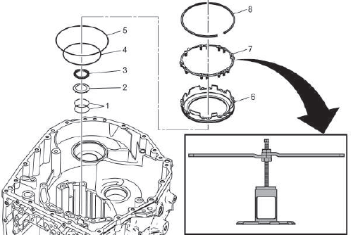
TORQUE CONVERTER FLUID SEAL INSTALLATION
- Torque Converter Fluid Seal
Procedure
Install seal with hand, then finish by tapping around perimeter with rubber mallet until properly seated.
NOTE: Install a NEW seal. Do NOT reuse the old seal.
TORQUE CONVERTER ASSEMBLY INSTALLATION
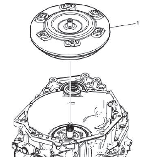
- Torque Converter
READ NEXT:
 Description and Operation
Transmission Identification Information
For automatic transmission AF50, the identification plate is on the top of
the transmission housing.
Aisin Warner transmission type
Fabrication line 1 = 00
Special Tools and Equipment
SPECIAL TOOLS
DT-26941
J-26941
Remover
DT-37228
J-37228
Seal Cutter
DT-43911
J-43911
Selector Shaft Seal
Remover
DT-44215
J-44215
Rear Seal Installer
DT-44809
J-44809
Output Shaft Seal
Installer
SEE MORE:
Diagnostic Information and Procedures
DTC B0072 or B0073
Diagnostic Instructions
Perform the Diagnostic System Check - Vehicle prior to using this
diagnostic procedure.
Review Strategy Based Diagnosis for an overview of the diagnostic
approach.
Diagnostic Procedure Instructions provides an overview of each
diagnostic category
Repair Instructions
Brake Pedal Position Sensor Calibration
Calibration Criteria
NOTE: Do not apply the brake pedal during the brake pedal position
sensor
calibration procedure. Any movement of the brake pedal during this
procedure will cause the calibration procedure to fail. If this occurs, the
brake pedal position
