Opel Insignia: Description and Operation
Transmission Identification Information
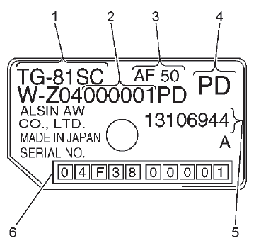
For automatic transmission AF50, the identification plate is on the top of the transmission housing.
- Aisin Warner transmission type
- Fabrication line 1 = 000001 - 500000 Fabrication line 2 = 500001 - 999999
- Transmission type (AF50)
- Model code
- GM parts number
- Production serial number
16 = Year of production (2016)
F = Month of production
- A: January
- B: February
- C: March
- D: April
- E: May
- F: June
- G: July
- H: August
- J: September
- K: October
- L: November
- M: December
38 = Model Designation
00001 = Production Serial Number
TRANSMISSION GENERAL DESCRIPTION
The AF50-8 is a compact, lightweight, next-generation electronically controlled 8-speed automatic transaxle that employs a ravigneaux-type planetary gear. It employs a high-precision clutch hydraulic control system for smooth, highly responsive gear shift feel.
Automatic Transaxle Features
Lock-up Control, Slip Control
Based on output rpm signals (NOUT), signals from the engine control unit (engine rpm and throttle opening) and vehicle speed, smooth lock up control is performed. Also, the slip rate is detected by adding input rpm signals (NIN), and slip control is performed.
Self Learning Control
The TCM helps provide smooth clutch engagement at gear shifting and smooth and delicate shifting while driving by performing shift control learning and garage shift control learning.
Neutral Control (N Control)
When the vehicle is at low speed or stopped in position "D", the transmission enters a neutral condition by releasing the clutch. By reducing drag loss of the torque converter, the load on the engine is lightened, fuel economy is enhanced, and idling vibration is reduced.
Manual Shift Control
By moving the shift lever from the "D" position into the manual shift position and shifting into + (upshift) or - (downshift), the driver can select the desired gear, enabling sporty driving that feels like a manual transmission.
A non-contact type shift position sensor has been adopted in the TCM. The sensor detects shift position by using the Hall Effect, which outputs specified voltage according to the shift position (P, R, N, D). The magnet position in the sensor changes when moving the shift lever, enabling the Hall IC to convert magnetic field strength into an electrical signal according to the shift position. Compared to the conventional contact type switch, the non-contact type sensor does not have contact points and is very compact. This makes it possible to integrate it with the TCM, improving reliability and durability.
If magnetic flux is applied perpendicularly to electric current flowing into a conductor or semiconductor, a potential difference, called Hall voltage, is generated perpendicularly in both the electric current and magnetic flux. This phenomenon is called the "Hall Effect".
A Hall IC is an electronic part that uses impetus caused by potential difference when a magnetic field is generated.
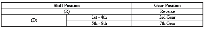
With the fail-safe function, if any malfunction should occur in the automatic transmission system, the TCM will output a control signal, and control will be performed to make traveling a minimum distance possible. If a shift solenoid malfunctions, the TCM will cancel the output of control signals to the solenoid. If this happens, oil pressure circuits alone will control automatic transmission gear shifting. The gears will shift as shown in the chart below.
The transmission may be operated in any of the following gear ranges:
PARK (P)
This position locks the front wheels and prevents the vehicle from rolling either forward or backward. PARK is the best position to use when starting the vehicle. Because the transmission utilizes a shift lock control system, it is necessary to fully depress the brake pedal before shifting out of PARK. For safety reasons, use the parking brake in addition to the PARK position.
REVERSE (R)
This position allows the vehicle to be operated in a rearward direction.
NEUTRAL (N)
This position allows the engine to be started and operated while driving the vehicle. If necessary, you may select this position in order to restart the engine with the vehicle moving. This position should also be used when towing the vehicle.
DRIVE (D)
Drive range should be used for all normal driving conditions for maximum efficiency and fuel economy. Drive range allows the transmission to operate in each of the 8 forward gear ratios. Downshifts to a lower gear, or higher gear ratio, are available for safe passing by depressing the accelerator or by manually selecting a lower gear in the manual mode range.
TRANSMISSION ADAPTIVE FUNCTIONS
The transmission control module (TCM) utilizes speed sensor data during commanded shifts to determine if a shift is occurring too fast (harsh) or too slow (soft). Transmission build variation and normal wear of the clutches can cause the shift time (the time required to apply a clutch) to be longer or shorter than desired. In order to compensate for these changes, the transmission control module (TCM) adjusts the current output to the various pressure control solenoid valves, to maintain the originally calibrated shift timing. This self-learning process is referred to as "adaptive learning" which is used to ensure consistent shift feel and increase transmission durability.
Electronic Component Description
Control Module
K71 Transmission Control Module
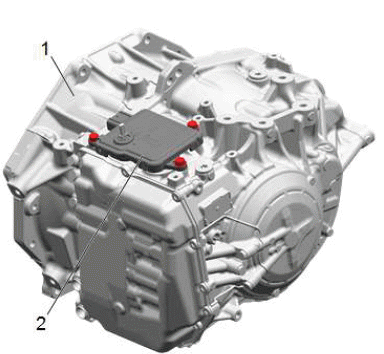
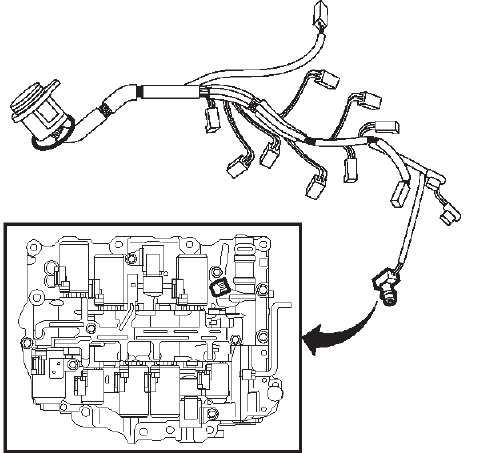
The TCM (2) is mounted directly on top of the transmission (1). The selector lever and transmission range sensor is integrated in the control module. The TCM is mounted so that the selector lever shaft goes through the control module. The selector lever position is calibrated with a scan tool, there is no mechanical adjustment.
An external 16-terminal connector connects to the vehicle's electrical system. Underneath the control module is another connector (33-terminal) that connects directly to the transmission. The TCM makes contact with all the transmission solenoids and sensors here.
NOTE: Magnetic fields from e.g. magnets and from high-current cables, such as starter cables and cables to auxiliary equipment, can interfere with the gear position sensor. A rule of thumb is max 1A per mm in distance from the control module. A starter cable carrying a current of 200A must therefore be kept at least 20 cm away from the control module.
The TCM has a microprocessor with clock, RAM memory and a programmable ROM. An internal bus connects the processor and memory with the I/O unit. The I/O unit reads values from the A/D converter for analogue inputs, digital inputs and bus, as well as activates the transistors' output stages.
Adaptive values are saved in a non-volatile memory (ROM). When changing the transmission, these values must be zeroed using scan tool. The values are will be zeroed automatically after replacing the control module using the scan tool.
B182 Gear Shift Position Sensor
A non-contact type shift position sensor is integrated in the TCM. The sensor detects shift position by using a hall effect sensor, which outputs specified voltage according to the shift position (P, R, N, D). The magnet position in the sensor changes when moving the shift lever, enabling the hall effect sensor to convert magnetic field strength into an electrical signal according to the shift position.
B81 Park/Neutral Position Switch
The park/neutral position (PNP) switch is part of the K71 Transmission Control Module (TCM) assembly. The TCM provides a ground to the K20 Engine Control Module in park and neutral. The K20 ECM sends a 12V trace on the PNP circuit to the K71 TCM, used for circuit diagnostics. The PNP provides a range signal (permission to crank) to the ECM to enable engine start.
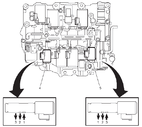
Pressure Control Solenoid Valves - Shifting
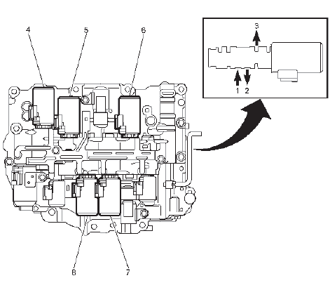
- In
- Out
- Exhaust
- Q27E Pressure Control Solenoid Valve 5
- Q27D Pressure Control Solenoid Valve 4
- Q27A Pressure Control Solenoid Valve 1
- Q27B Pressure Control Solenoid Valve 2
- Q27C Pressure Control Solenoid Valve 3
Q27A Pressure Control Solenoid Valve 1
The PWM controlled solenoid valve is mounted in the transmission valve housing and controls the pressure in C1.
The valve is active in shift position D - (gears 1, 2, 3, 4 and 5).
The control module activates the valve by pulsing it with B+ (300 Hz PWM). The current varies between 100-1100 mA. The solenoid is normally closed and the hydraulic pressure decreases as the current increases.
Q27B Pressure Control Solenoid Valve 2
The PWM controlled solenoid valve is mounted in the transmission valve housing and controls the pressure in C2.
The valve is active in shift position D - (gears 5, 6, 7, 8).
The control module activates the valve by pulsing it with B+ (300 Hz PWM). The current varies between 100-1100 mA. The solenoid is normally closed and the hydraulic pressure decreases as the current increases.
Q27C Pressure Control Solenoid Valve 3
The PWM controlled solenoid valve is mounted in the transmission valve housing and controls the pressure in C3.
The valve is active in shift position P, R, N, D - (gears 3 and 7).
The control module activates the valve by pulsing it with B+ (300 Hz PWM). The current varies between 100-1100 mA. The solenoid is normally closed and the hydraulic pressure decreases as the current increases.
Q27D Pressure Control Solenoid Valve 4
The PWM controlled solenoid valve is mounted in the transmission valve housing and controls the pressure in clutch C4. The valve is active in shift position D - (gears 4 and 6).
The control module activates the valve by pulsing it with B+ (300 Hz PWM). The current varies between 100-11000 mA. The solenoid is normally closed and the hydraulic pressure decreases as the current increases.
Q27E Pressure Control Solenoid Valve 5
The PWM controlled solenoid valve is mounted in the transmission valve housing and controls the pressure in C5.
The valve is active in shift position D - (gears 2 and 8).
The control module activates the valve by pulsing it with B+ (300 Hz PWM). The current varies between 100-1100 mA. The solenoid is normally closed and the hydraulic pressure decreases as the current increases.
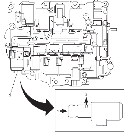
Pressure Control Solenoid Valve - Non-Shifting
- In
- Out
- Exhaust
- Q23 Line Pressure Control Solenoid Valve
- Q39A Torque Converter Clutch Pressure Control Solenoid Valve
Q23 Line Pressure Control Solenoid Valve - Pressure Control Solenoid Valve 6
The PWM controlled solenoid valve is mounted in the transmission valve housing and controls the transmission line pressure
The control module activates the valve by pulsing it with B+ (300 Hz PWM). The current varies between 100-1100 mA. The solenoid is normally open and the hydraulic pressure increases as the current increases.
Q39A Torque Converter Clutch Pressure Control Solenoid Valve
The solenoid valve is mounted in the transmission valve housing and controls the pressure for the torque converter clutch The pressure is modulated so that full, partial or no engagement is achieved.
The control module activates the valve by pulsing it with B+ (300 Hz PWM). The current varies between 100-1100 mA. The solenoid is normally closed and the hydraulic pressure increases the current increases.
Q27G Pressure Control Solenoid Valve 7 { If equipped }
Q27G Pressure Control Solenoid Valve 7 { If equipped }
The normally closed solenoid valve is mounted in the transmission valve housing and is used to engage the C1 clutch during an autostop event.
The control module activates the valve by applying B+.
Shift Solenoids
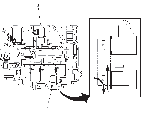
- On
- Off
- Q32A Shift Solenoid Valve 1
- Q32B Shift Solenoid Valve 2
Q32A Shift Solenoid Valve 1 & Q32B Shift Solenoid Valve 2
The normally closed solenoid valves are mounted in the transmission valve housing and are turned on and off by the TCM. Activating these components will cause 1st gear engine braking or a gear shift, depending on the state of the other solenoids within the transmission.
The control module activates the valves by applying B+. The solenoid is grounded through its housing
Speed Sensors
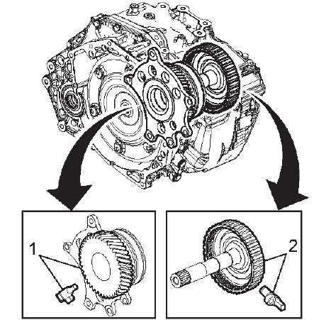
- Counter Drive Gear & B14A Transmission Output Shaft Speed Sensor
- C2 Clutch Drum & B14C Transmission Input Shaft Speed Sensor
B14A Transmission Output Shaft Speed Sensor
The sensor is mounted inside the valve housing in the rear part of the transmission and measures the transmission output shaft speed. This value is used by TCM to determine gear change points and vehicle speed. The sensor contains a hall-effect sensor and additional electronics that processes the signal. It detects the change of strength of the magnetic field caused by the reluctor ring. When the strength changes, the sensor changes the amount of current it consumes. This results in a square wave signal of the current, while the voltage stays constant. The control module detects the frequency in which the current changes, which is proportional to the rotational speed. The 2 - wire hall effect sensor faces the counter drive gear, there are 56 teeth on the gear.
B14C Transmission Input Shaft Speed Sensor
The sensor is mounted inside the valve housing in the front part of the transmission and measures the speed of the transmission input shaft. This value is used by the TCM to calculate the actual gear change time and to regulate lock up. The sensor contains a hall-effect sensor and additional electronics that processes the signal. It detects the change of strength of the magnetic field caused by the reluctor ring. When the strength changes, the sensor changes the amount of current it consumes. This results in a square wave signal of the current, while the voltage stays constant.
The control module detects the frequency in which the current changes, which is proportional to the rotational speed.
The 2 - wire hall effect sensor faces the indentations on the C2 clutch drum, there are 36 indentations on the drum.
Temperature Sensor
B13 Transmission Fluid Temperature Sensor
The temperature sensor is mounted in the transmission valve housing and informs the control module about the current temperature. The value is used to correct the PWM ratio to the solenoids so that the gear changes are not affected by the viscosity of the oil. It is also used to activate the special gear change program in case of overheating.
The sensor comprises an NTC resistor built into a plastic casing. The NTC resistor characteristic means that the resistance drops as the temperature rises. The NTC resistor is supplied with 5V through a pull up from control module.
READ NEXT:
 Special Tools and Equipment
SPECIAL TOOLS
DT-26941
J-26941
Remover
DT-37228
J-37228
Seal Cutter
DT-43911
J-43911
Selector Shaft Seal
Remover
DT-44215
J-44215
Rear Seal Installer
DT-44809
J-44809
Output Shaft Seal
Installer
Specifications
FASTENER SPECIFICATIONS
Single Use Non-Threaded Fasteners/Components
NOTE:
All fasteners/components listed in this table MUST BE DISCARDED and replaced
with NEW
after removal.
Application
Power Trans
SEE MORE:
Diagnostic Information and Procedures
DTC B2745
Diagnostic Instructions
Perform the Diagnostic System Check - Vehicle prior to using this
diagnostic procedure.
Review Strategy Based Diagnosis for an overview of the diagnostic
approach.
Diagnostic Procedure Instructions provides an overview of each
diagnostic category.
DTC Des
Description and Operation
Active Safety System Description and Operation
The active safety system is a comprehensive feature set designed to help a
driver avoid collisions or
reduce crash damage while driving, backing, and parking. The K124 Active Safety
Control Module is
the primary controller for the active safety system
