Opel Insignia: Repair Instructions
Hose Clamp Replacement Guidelines - Spring Type
Special Tools
- BO-38185 Hose Clamp Pliers
- GE-47622 Hose Clamp Pliers.
Equivalent regional tools: Special Tools
Spring Type Hose Clamp Replacement Guidelines
.png)
Vehicles utilize spring type hose clamps (1) to secure joints in which fluids, gases, or engine vacuum can travel to various vehicle systems. Spring type hose clamps are engineered to provide the proper amount of tension to maintain a leak & maintenance free joint for the life of the vehicle.
Spring type hose clamps have a special coating applied to the exterior of the clamp that is engineered to resist rust/corrosion, improve durability and increase the life of the hose clamp. If the coating is damaged, rust/corrosion could form resulting in the need to replace the hose clamp.
Many spring type hose clamps within GM utilize a small amount of adhesive placed directly on the hose clamp to secure the clamp to the mating hose for manufacturing purposes. Over time the strength of the adhesive will deteriorate. It is extremely important when a technician is attempting to service a joint or remove the hose clamp, that the clamp is not rotated or repositioned so that is tears and/or damages the hose. In this case, the hose and clamp must both be replaced.
When repairing a vehicle it is very important to observe the condition of both the hose and the spring type hose clamp as well as the orientation of the clamp to the hose.
If the spring type hose clamp (s) have any of the following conditions on any area of the clamp, replace the clamp (s) immediately.
- Rust/Corrosion
- Cracks
- Physical damage
- Leakage attributed to the retention of the clamp
Removing The Spring Type Hose Clamp
While keeping the hose stationary, use BO-38185 Hose Clamp Pliers or GE-47622 Hose Clamp Pliers and release the spring type hose clamp tension while attempting to separate the hose clamp from the hose.
- If the spring type hose clamp will not easily separate from the hose and/or the clamp tears or damages the hose, both the hose and hose clamp must be replaced
- If the spring type hose clamp is easily removed from the hose, the clamp can be reused provided that the clamp does not have any of the conditions as noted above.
If The Spring Type Hose Clamp Is Being Reused
It is extremely important that the spring type hose clamp is orientated to the hose in the exact same position as it was installed during vehicle assembly so that the hose clamp is not damaged or the hose clamp does not contact or damage any adjacent components. Do not use any type of adhesive on the hose clamp prior to installation.
When Reusing The Spring Type Hose Clamp and Replacing The Hose
- The inside and outside hose diameter must be identical between the new hose and the existing hose to guarantee proper hose clamp tension and joint integrity.
- Always place the existing spring type hose clamp in the same orientation as it was positioned prior to separating the joint. The new hose might have a marking on the hose indicating the correct position of a hose clamp, which should re-confirm the correct hose clamp position. The hose clamp should not contact any adjacent components after installation.
When Reusing The Spring Type Hose Clamp with an Existing Hose
Always place the existing spring type hose clamp in the same orientation as it was positioned prior to separating the joint. The existing hose might have an indentation or compression mark on the hose from where the hose clamp was installed previously. The hose clamp should identically overlay this position.
The existing hose might also have a marking on the hose indicating the correct position of the hose clamp, which should re-confirm the correct hose clamp position. The hose clamp should not contact any adjacent components after installation.
If The Spring Type Hose Clamp Is Being Replaced
If the hose clamp needs to be replaced, always replace the hose as part of the service repair. It is extremely important that a new spring type hose clamp is orientated to the hose in the exact same position as it was installed during vehicle assembly so that the hose clamp is not damaged or the hose clamp does not contact or damage any adjacent components. Do not use any type of adhesive on the hose clamp prior to installation.
When Replacing The Spring Type Hose Clamp and Replacing The Hose
- The inside and outside hose diameter must be identical between the new hose and the existing hose to guarantee proper hose clamp tension and joint integrity.
- Always place the new spring type hose clamp in the same orientation as it was positioned prior to separating the joint. The new hose might have a marking on the hose indicating the correct position of a hose clamp, which should re-confirm the correct hose clamp position. The hose clamp should not contact any adjacent components after installation.
When Replacing The Spring Type Hose Clamp with an Existing Hose
Always place the new spring type hose clamp in the same orientation as it was positioned prior to separating the joint. The existing hose might have an indentation or compression mark on the hose from where a hose clamp was installed previously. The hose clamp should identically overlay this position. The existing hose might also have a marking on the hose indicating the correct position of the hose clamp, which should re-confirm the correct hose clamp position. The hose clamp should not contact any adjacent components after installation.
Cooling System Draining and Filling (Static)
Special Tools
GE-26568 Coolant and Battery Tester
WARNING: With a pressurized cooling system, the coolant temperature in the radiator can be considerably higher than the boiling point of the solution at atmospheric pressure. Removal of the surge tank cap, while the cooling system is hot and under high pressure, causes the solution to boil instantaneously with explosive force. This will cause the solution to spew out over the engine, the fenders, and the person removing the cap. Serious bodily injury may result.
NOTE: Use only a GM released anti-freeze mixture and ensure a concentration of 50 percent water to 50 percent antifreeze. Antifreeze does not just prevent the cooling system from freezing up, it also protects all the components that are in contact with coolant from rust/limescale deposits. As a result, antifreeze should always be added, even in tropical countries.
In addition to the anti-freeze mixture, water quality also plays an important role. Potable tap water should normally suffice to fulfil this requirement.
The quality of regenerated sea water is not suitable.
Damage may also be caused to the engine if unauthorized anti-freeze agent is used.
If radiator, cylinder head or cylinder head seal have been replaced the old coolant must not be re-used.
Cooling System Draining
1. Radiator Surge Tank Cap - Remove.
2. Raise and support the vehicle.
3.
.png)
{ If equipped }Underbody Skid Shield (2) - Remove.
4.
.png)
Front Compartment Air Deflector (4) - Remove.
5. Place a drain pan under the drain cock.
6.
.png)
Attach a rubber hose to the radiator drain port to guide the coolant into the drain pan. (1, 2).
7. Radiator Drain Cock (3) - Open.
8. Drain the cooling system.
9. Radiator Drain Cock (3) - Close.
10. Remove the drain hose (1) at the radiator drain port.
11.
.png)
Front Compartment Air Deflector (4) - Install.
12.
.png)
{ If equipped }Underbody Skid Shield (2) - Remove.
13. Lower the vehicle.
Cooling System Filling
CAUTION: The procedure below must be followed. Improper coolant level could result in a low or high coolant level condition, causing engine damage.
NOTE: Use a 50/50 mixture of DEX-COOL antifreeze and clean, drinkable water.
1. Slowly fill the cooling system with a 50/50 coolant mixture until the coolant level is visible and stable. Approximate Fluid Capacities.
2. Install the pressure cap loosely (threaded on about one turn).
3. Start the engine and raise the engine speed to 2500 RPM and hold it there for 40 seconds, then shut engine off.
4. Remove the pressure cap and fill the coolant system until the level is visible and stable.
5. Install the pressure cap loosely (threaded on about one turn).
6. Start the engine and raise the engine speed to 2500 RPM and hold it there for 30 seconds, then shut engine off.
7. Remove the pressure cap and fill the coolant system until the level is visible and stable.
8. Install the pressure cap loosely (threaded on about one turn).
9. Start the engine and raise the engine speed to 2500 RPM and hold it there for 20 seconds, then shut engine off.
10. Fill the radiator surge tank to the indicator line, then add 400 milliliters (13.5 ounces) more.
11. Install the pressure cap, fully threaded on.
12. Start the engine and run it above 2500 RPM until it is hot enough to open the thermostat, this will allow the trapped air to be purged from the engine.
13. Complete a series of three, 4-second-duration idles with 4-second-duration 3000 RPM cycles.
14. Turn the engine off and allow it to cool down to room temperature.
15.
.png)
Fill the radiator surge tank to the indicator line (1).
16. Inspect the concentration of the engine coolant, using the GE-26568 tester.
17. Rinse away any excess coolant from the engine and the engine compartment.
Cooling System Draining and Filling (GE 47716)
Special Tools
- GE-26568 Coolant and Battery Fluid Tester
- GE-42401 Radiator Cap and Surge Tank Test Adapter
- GE-47716 Vac N Fill Coolant Refill Tool
Draining Procedure
WARNING: With a pressurized cooling system, the coolant temperature in the radiator can be considerably higher than the boiling point of the solution at atmospheric pressure. Removal of the surge tank cap, while the cooling system is hot and under high pressure, causes the solution to boil instantaneously with explosive force. This will cause the solution to spew out over the engine, the fenders, and the person removing the cap. Serious bodily injury may result.
1. Remove the coolant pressure cap.
2. Raise and support the vehicle. Lifting and Jacking the Vehicle.
3.
.png)
{ If equipped }Underbody Skid Shield (2) - Remove.
4.
.png)
Front Compartment Air Deflector (4) - Remove.
5. Place a drain pan under the drain cock.
6.
.png)
Attach a rubber hose to the radiator drain port to guide the coolant into the drain pan. (1, 2).
7. Radiator Drain Cock (3) - Open.
8. Drain the cooling system.
9. Radiator Drain Cock (3) - Close.
10. Remove the drain hose (1) at the radiator drain port (2).
11. Remove the drain pan.
12.
.png)
Front Compartment Air Deflector (4) - Install.
13.
.png)
{ If equipped }Underbody Skid Shield (2) - Install.
14. Lower the vehicle.
15. Inspect the coolant.
16. Follow the appropriate procedure based on the condition of the coolant.
- Normal in appearance - Follow the filling procedure.
- Discolored - Follow the flush procedure.
Vac-N-Fill Procedure
WARNING: To avoid being burned, do not remove the radiator cap or surge tank cap while the engine is hot. The cooling system will release scalding fluid and steam under pressure if radiator cap or surge tank cap is removed while the engine and radiator are still hot.
1. Install the GE-42401 adapter onto the coolant surge tank.
2. Attach the Vac-N-Fill cap to the GE-42401 adapter.
3.
.png)
Attach the vacuum gauge assembly (1) to the Vac-N-Fill cap.
4.
.png)
Attach the fill hose (2) to the barb fitting on the vacuum gauge assembly (1).
Ensure that the valve is closed.
5.
.png)
NOTE: Use a 50/50 mixture of DEX-COOL antifreeze and clean, drinkable water.
Always use more coolant than necessary. This will eliminate air from being drawn into the cooling system.
Pour the coolant mixture into the graduated reservoir (1).
6. Place the fill hose in the graduated reservoir (1).
NOTE: Prior to installing the vacuum tank onto the graduated reservoir, ensure that the drain valve located on the bottom of the tank is closed.
7. Install the vacuum tank (2) on the graduated reservoir with the fill hose routed through the cut-out area (3) in the vacuum tank.
8.
.png)
Attach the venturi assembly (1) to the vacuum tank (2).
9.
.png)
Attach a shop air hose to the venturi assembly (1).
Ensure the valve (2) on the venturi assembly is closed.
10.
.png)
Attach the vacuum hose (1) to the vacuum gauge assembly (2) and the vacuum tank (3).
11.
.png)
Open the valve (1) on the venturi assembly (2). The vacuum gauge will begin to rise and a hissing noise will be present.
12.
.png)
Continue to draw vacuum until the needle stops rising (1). This should be 610-660 mm Hg (24-26 in Hg).
Cooling hoses may start to collapse. This is normal due to vacuum draw.
13. To aid in the fill process, position the graduated reservoir above the coolant fill port.
14.
.png)
Slowly open the valve (1) on the vacuum gauge assembly (2). When the coolant reaches the top of the fill hose, close the valve. This will eliminate air from the fill hose.
15. Close the valve on the venturi assembly.
16. If there is a suspected leak in the cooling system, allow the system to stabilize under vacuum and monitor for vacuum loss.
If vacuum loss is observed, refer to Loss of Coolant.
17. Open the valve on the vacuum gauge assembly. The vacuum gauge will drop as coolant is drawn into the system.
18.
.png)
Once the vacuum gauge reaches zero (1), close the valve on the vacuum gauge assembly and repeat steps 11 - 17.
19. Detach the Vac-N-Fill cap from the GE-42401 adapter.
20. Remove the GE-42401 adapter from the coolant surge tank.
21. Add coolant to the system as necessary.
22. Inspect the concentration of the coolant mixture using GE-26568 tester.
NOTE: After filling the cooling system, the extraction hose can be used to remove excess coolant to achieve the proper coolant level.
23. Detach the vacuum hose from the vacuum gauge assembly.
24.
.png)
Attach the extraction hose (1) to the vacuum hose (2).
25.
.png)
Open the valve (1) on the venturi assembly (2) to start a vacuum draw.
26.
.png)
Use the extraction hose (1) to draw out coolant to the proper level.
27. The vacuum tank has a drain valve on the bottom of the tank. Open the valve to drain coolant from the vacuum tank into a suitable container for disposal.
28. Install the surge tank cap.
Coolant System Flushing
WARNING: In order to avoid personal injury, do not remove the cap or open the cooling system drains from a hot system. Allow the system to cool first.
NOTE: Do not use a chemical flush.
Store used coolant in the proper manner, such as in a used engine coolant holding tank.
Do not pour used coolant down a drain. Ethylene glycol antifreeze is a very toxic chemical.
Do not dispose of coolant into the sewer system or ground water. This is illegal and ecologically unsound.
Various methods and equipment can be used to flush the cooling system. If special equipment is used, such as a back flusher, follow the manufactures instruction. However, always remove the thermostat before back flushing the system.
1. Apply the park brake.
2. Drain the coolant. Refer to Cooling System Draining and Filling (Static) or Cooling System Draining and Filling (GE 47716).
3. Fill the coolant system with clean drinkable water. Refer to Cooling System Draining and Filling (Static) or Cooling System Draining and Filling (GE 47716).
4. Start the engine and run at 2.000 RPM until the thermostat opens.
5. Turn OFF the engine.
6. Drain the coolant system. Refer to Cooling System Draining and Filling (Static) or Cooling System Draining and Filling (GE 47716).
7. Repeat the above procedure until the water from the coolant system is colorless.
8. Drain the coolant system. Refer to Cooling System Draining and Filling (Static) or Cooling System Draining and Filling (GE 47716).
9. Add 3.8 liters (1.0 gal) of concentrated antifreeze since there will be some water in the system.
10. Add a mixture of 50/50 antifreeze and clean drinkable water until the level stabilizes at the weld seam on the surge tank. Refer to Cooling System Draining and Filling (Static) or Cooling System Draining and Filling (GE 47716).
Radiator Cleaning
WARNING: NEVER spray water on a hot heat exchanger. The resulting steam could cause personal injury.
CAUTION: The heat exchanger fins are necessary for good heat transfer. Do not brush the fins. This may cause damage to the fins, reducing heat transfer.
NOTE: Remove bugs, leaves, dirt and other debris by blowing compressed air through the engine side of the radiator.
- Some conditions may require the use of warm water and a mild detergent.
- Clean the A/C condenser fins.
- Clean between the A/C condenser and radiator.
- Clean the radiator cooling fins.
- Straighten any damaged cooling fins.
RADIATOR SURGE TANK REPLACEMENT
Removal Procedure
WARNING: With a pressurized cooling system, the coolant temperature in the radiator can be considerably higher than the boiling point of the solution at atmospheric pressure. Removal of the surge tank cap, while the cooling system is hot and under high pressure, causes the solution to boil instantaneously with explosive force. This will cause the solution to spew out over the engine, the fenders, and the person removing the cap. Serious bodily injury may result.
1.
.png)
Retainer (3) - Unclip.
2. { If equipped }Power Transfer Unit Vent Hose (4) - Position aside.
3. Clamp (2, 6) - Disengage - Hose Clamp Replacement Guidelines - Spring Type.
4. Engine Coolant Air Bleed Hose (1) @ Radiator Surge Tank - Remove.
5. Hose (5) @ Radiator Surge Tank - Remove.
6.
.png)
Radiator Surge Tank Bolt (2) - Remove.
7. Radiator Surge Tank (1) @ Radiator Surge Tank Bracket (3) - Remove.
8. Radiator Surge Tank (1) - Remove.
Installation Procedure
1.
.png)
Radiator Surge Tank (1) - Install.
2. Radiator Surge Tank (1) @ Radiator Surge Tank Bracket (3) - Install.
CAUTION: Refer to Fastener Caution.
3. Radiator Surge Tank Bolt (2) - Install and tighten9N.m (80 lb in).
4.
.png)
Hose (5) @ Radiator Surge Tank - Install.
5. Engine Coolant Air Bleed Hose (1) @ Radiator Surge Tank - Install.
6. Clamp (2, 6) - Install - Hose Clamp Replacement Guidelines - Spring Type.
7. { If equipped }Power Transfer Unit Vent Hose (4) - Reposition.
8. Retainer (3) - Install.
9. Fill the cooling system to the proper level. Cooling System Draining and Filling (Static) or Cooling System Draining and Filling (GE 47716).
10. Start the engine and check for coolant leaks.
RADIATOR SURGE TANK INLET HOSE REPLACEMENT (3.6L LGX)
Removal Procedure
1.
.png)
Radiator Surge Tank Inlet Hose Clamp (1) - Disengage - Hose Clamp Replacement Guidelines - Spring Type.
2. Radiator Surge Tank Inlet Hose (2) @ Radiator Surge Tank - Remove.
3. Intake Manifold Cover - Remove - Intake Manifold Cover Replacement.
4.
.png)
Radiator Surge Tank Inlet Hose Clamp (1) - Disengage - Hose Clamp Replacement Guidelines - Spring Type.
5. Radiator Surge Tank Inlet Hose (2) @ Engine Coolant Air Bleed Pipe - Remove.
6.
.png)
Radiator Surge Tank Inlet Hose Clip (1) @ Intake Manifold - Remove [2x].
7. Transfer components as necessary.
Installation Procedure
1.
.png)
Radiator Surge Tank Inlet Hose Clip (1) @ Intake Manifold - Install [2x]
2.
.png)
Radiator Surge Tank Inlet Hose (2) @ Engine Coolant Air Bleed Pipe - Install.
3. Radiator Surge Tank Inlet Hose Clamp (1) - Engage.
4. Intake Manifold Cover - Install - Intake Manifold Cover Replacement.
5.
.png)
Radiator Surge Tank Inlet Hose (2) @ Radiator Surge Tank - Install.
6. Radiator Surge Tank Inlet Hose Clamp (1) - Engage.
7. Fill the cooling system.
8. Start the engine and check for coolant leaks.
RADIATOR SURGE TANK INLET HOSE REPLACEMENT (2.0L LTG)
.png)
Preliminary Procedure
Drain the cooling system.
- Radiator Surge Tank Inlet Hose Clamp [2x]
Procedure
Hose Clamp Replacement Guidelines - Spring Type
- Radiator Surge Tank Inlet Hose
Procedure
1. Fill the cooling system.
2. Check the cooling system for leaks.
RADIATOR INLET HOSE REPLACEMENT (2.0L LTG)
.png)
Preliminary Procedure
Drain the cooling system.
- Radiator Inlet Hose Clamp [2x]
Procedure
Reposition the radiator inlet hose clamps using GE-47622 Hose Clamp Pliers.
Special Tools GE-47622 Hose Clamp Pliers Special Tools
- Radiator Inlet Hose
Procedure
1. Fill the coolant to the proper level.
2. Inspect for coolant leaks.
RADIATOR INLET HOSE REPLACEMENT (3.6L LGX)
Removal Procedure
1. Drain the cooling system.
2. Air Cleaner Assembly - Remove.
3. Engine Wiring Harness - Reposition.
4.
.png)
Radiator Inlet Hose Clamp (1) - Disengage.
5. Radiator Inlet Hose (2) @ Engine Coolant Thermostat Housing Inlet Pipe - Remove.
6.
.png)
Radiator Inlet Hose Clamp (1) - Disengage.
7. Radiator Inlet Hose (2) @ Radiator - Remove.
8. Radiator Inlet Hose (2) - Remove.
Installation Procedure
1.
.png)
Radiator Inlet Hose (2) @ Radiator - Install.
2. Radiator Inlet Hose Clamp (1) - Engage.
3.
.png)
Radiator Inlet Hose (2) @ Engine Coolant Thermostat Housing Inlet Pipe - Install.
4. Radiator Inlet Hose Clamp (1) - Engage.
5. Engine Wiring Harness - Install.
6. Air Cleaner Assembly - Install.
7. Fill the cooling system.
8. Start the engine and check for coolant leaks.
RADIATOR OUTLET HOSE REPLACEMENT (2.0L LTG)
.png)
Preliminary Procedures
1. Drain the cooling system.
2. Air Cleaner Outlet Duct Replacement.
- Radiator Outlet Hose Clamp [2x]
Procedure
Reposition the radiator outlet hose clamps using GE-47622 Hose Clamp Pliers.
Special Tools GE-47622 Hose Clamp Pliers Special Tools
- Radiator Outlet Hose
Procedure
1. Fill the coolant to the proper level.
2. Inspect for coolant leaks.
RADIATOR OUTLET HOSE REPLACEMENT (3.6L LGX WITHOUT ENGINE OIL COOLER)
Removal Procedure
1. Drain the cooling system.
2. Front Bumper Fascia - Remove.
3.
.png)
Radiator Outlet Hose Clamp (1) - Disengage.
4. Radiator Outlet Hose (2) @ Water Pump Inlet Pipe - Remove.
5.
.png)
Radiator Outlet Hose Clamp (1) - Disengage.
6. Radiator Outlet Hose (2) @ Radiator - Remove.
7. Radiator Outlet Hose (2) - Remove.
Installation Procedure
1.
.png)
Radiator Outlet Hose (2) @ Radiator - Install.
2. Radiator Outlet Hose Clamp (1) - Engage.
3.
.png)
Radiator Outlet Hose (2) @ Water Pump Inlet Pipe - Install.
4. Radiator Outlet Hose Clamp (1) - Engage.
5. Front Bumper Fascia - Install.
6. Fill the cooling system.
7. Start the engine and check for coolant leaks.
RADIATOR OUTLET HOSE REPLACEMENT (3.6L LGX WITH ENGINE OIL COOLER)
Removal Procedure
1. Drain the cooling system.
2. Front Bumper Fascia - Remove.
3.
.png)
Radiator Outlet Hose Clamp (1) - Disengage.
4. Radiator Outlet Hose (2) @ Water Pump Inlet Pipe - Remove.
5.
.png)
Radiator Outlet Hose Clamp (1) - Disengage.
6. Radiator Outlet Hose (2) @ Radiator - Remove.
7.
.png)
Radiator Outlet Pipe Bolt (1) @ Drivetrain and Front Suspension Cradle - Remove [2x].
8.
.png)
Radiator Outlet Hose Clamp (1) - Disengage.
9. Radiator Outlet Hose (2) @ Engine Oil Cooler - Remove.
10. Radiator Outlet Hose (2) - Remove.
Installation Procedure
1.
.png)
Radiator Outlet Hose (2) @ Engine Oil Cooler - Install.
2. Radiator Outlet Hose Clamp (1) - Engage.
3.
.png)
Radiator Outlet Hose (2) @ Radiator - Install.
4. Radiator Outlet Hose Clamp (1) - Engage.
5.
.png)
CAUTION: Refer to Fastener Caution.
Radiator Outlet Pipe Bolt (1) - @ Drivetrain and Front Suspension Cradle - Install and tighten [2x] 9 N.m (80 lb in).
6.
.png)
Radiator Outlet Hose (2) @ Water Pump Inlet Pipe - Install.
7. Radiator Outlet Hose Clamp (1) - Engage.
8. Front Bumper Fascia - Install.
9. Fill the cooling system to the proper level.
10. Start the engine and check for coolant leaks.
Engine Coolant Fan Wiring Harness Replacement (2.0L LTG)
Removal Procedure
1. Front Bumper Fascia Center Support - Remove.
2.
.png)
Clip (2) - Remove.
3. Disconnect the electrical connector. (1).
4.
.png)
Clip (1) - Remove [2x].
5.
.png)
Clip (1) - Remove.
6. Engine Coolant Fan Electrical Connector (2) - Disconnect [2x].
7.
.png)
Clip (1) - Remove [2x].
8.
.png)
Ground Cable Nut (1) - Remove.
9. Ground Cable (2) - Remove.
10.
.png)
Clip (1, 4) - Remove [2x].
11. Electrical Connector (3) @ Air Conditioning Refrigerant Pressure Sensor (2) - Disconnect.
12.
.png)
Clip (2) - Remove.
13. Electrical Connector (1) @ Body Wiring Harness - Disconnect.
14.
.png)
Engine Coolant Fan Wiring Harness (1) - Remove.
Installation Procedure
1.
.png)
Engine Coolant Fan Wiring Harness (1) - Install.
2.
.png)
Electrical Connector (1) @ Body Wiring Harness - Connect.
3. Clip (2) - Install.
4.
.png)
Electrical Connector (3) @ Air Conditioning Refrigerant Pressure Sensor (2) - Connect.
5. Clip (1, 4) - Install [2x].
6.
.png)
Ground Cable (2) - Install.
CAUTION: Refer to Fastener Caution.
7. Ground Cable Nut (1) - Install and tighten9N.m (80 lb in).
8.
.png)
Clip (1) - Install [2x].
9.
.png)
Engine Coolant Fan Electrical Connector (2) - Connect [2x].
10. Clip (1) - Install.
11.
.png)
Clip (1) - Install [2x].
12.
.png)
Connect the electrical connector. (1).
13. Clip (2) - Install.
14. Front Bumper Fascia Center Support - Install.
Engine Coolant Fan Wiring Harness Replacement (3.6L LGX)
Removal Procedure
1. Front Bumper Fascia - Remove.
2. Headlamp- Left Side - Remove.
3.
.png)
Engine Coolant Fan Wiring Harness (1) @ Air Conditioning Refrigerant Pressure Sensor - Disconnect.
4. Engine Coolant Fan Wiring Harness (2) @ Air Conditioning Evaporator Tube - Unclip.
5.
.png)
Engine Coolant Fan Wiring Harness (1) @ Radiator - Remove.
6.
.png)
Engine Coolant Fan Wiring Harness (1) @ Engine Coolant Fan Motor - Disconnect.
7.
.png)
Ground Nut (1) - Remove.
8. Engine Coolant Fan Wiring Harness (2) @ Stud - Remove.
9.
.png)
Engine Coolant Fan Wiring Harness (1) @ Engine Wiring Harness - Disconnect [2x].
10.
.png)
Engine Coolant Fan Wiring Harness (1) @ Engine Coolant Fan Motor - Disconnect.
11.
.png)
NOTE: Typical wiring harness shown. Individual wiring harnesses may differ based on option content.
Remove the wiring harness retainers and wiring harness (1) from the engine coolant fan as an assembly.
Installation Procedure
1.
.png)
NOTE: Typical wiring harness shown. Individual wiring harnesses may differ based on option content.
Install the wiring harness retainers and wiring harness (1) to the engine coolant fan as an assembly.
2.
.png)
Engine Coolant Fan Wiring Harness (1) @ Engine Coolant Fan Motor - Connect.
3.
.png)
Engine Coolant Fan Wiring Harness (1) @ Engine Wiring Harness - Connect [2x].
4.
.png)
Engine Coolant Fan Wiring Harness (2) @ Stud - Install.
CAUTION: Fastener Caution.
5. Ground Nut (1) - Install and tighten9N.m (80 lb in).
6.
.png)
Engine Coolant Fan Wiring Harness (1) @ Engine Coolant Fan Motor - Connect.
7.
.png)
Engine Coolant Fan Wiring Harness (1) @ Radiator - Install.
8.
.png)
Engine Coolant Fan Wiring Harness (2) @ Air Conditioning Evaporator Tube - Clip.
9. Engine Coolant Fan Wiring Harness (1) @ Air Conditioning Refrigerant Pressure Sensor - Connect.
10. Headlamp- Left Side - Install.
11. Front Bumper Fascia - Install.
Radiator Lower Bracket Replacement - Left Side
.png)
Preliminary Procedure
Radiator Replacement (2.0L LTG) or Radiator Replacement (3.6L LGX).
- Radiator Lower Bracket
Procedure
Depress the locking tab on the bracket to remove.
RADIATOR LOWER BRACKET REPLACEMENT - RIGHT SIDE
.png)
Preliminary Procedure
Radiator Replacement (2.0L LTG) or Radiator Replacement (3.6L LGX).
- Radiator Lower Bracket
Procedure
Depress the locking tab on the bracket to remove.
RADIATOR UPPER BRACKET REPLACEMENT - BODY SIDE
.png)
- Radiator Upper Mount Bracket Bolt
CAUTION: Fastener Caution
Tighten 7N.m (62 lb in)
- Radiator Upper Bracket Nut
Tighten 7N.m (62 lb in)
- Radiator Upper Bracket
RADIATOR UPPER BRACKET REPLACEMENT - RADIATOR SIDE
.png)
Preliminary Procedure
Radiator Upper Bracket Replacement - Body Side.
- Radiator Upper Bracket
Procedure
Depress the locking tab on the bracket to remove.
NOTE: Left side shown, right side similar.
ENGINE OIL COOLER REPLACEMENT (LTG)
Removal Procedure
1. Drain the cooling system.
2. Remove the engine oil filter.
3. Warm Up Three-Way Catalytic Converter - Remove - Warm Up Three-Way Catalytic Converter Replacement (2.0L LTG).
4. Oil Pump Flow Control Valve Heat Shield Replacement - Remove.
5.
.png)
Remove the engine oil cooler pipe fastener. (1).
6. Disconnect the inlet and outlet hoses from the engine oil cooler. (2).
7.
.png)
Remove the engine oil cooler connector (1).
8. Remove the engine oil cooler. (2).
9. Remove and DISCARD the seal. (3).
Installation Procedure
1.
.png)
When installing the engine oil cooler, position the engine oil cooler so that the tab (1) is against the engine block (2).
2.
.png)
Install a NEW seal. (3)
3. Install the engine oil cooler. (2)
CAUTION: Refer to Component Fastener Tightening Caution.
4. Install the engine oil cooler connector. 50 N.m (37 lb ft)
5.
.png)
Install the oil cooler inlet and outlet hoses. (2) Hose Clamp Replacement Guidelines - Spring Type.
CAUTION: Refer to Fastener Caution.
6. Install the engine oil cooler pipe fastener.10 N.m (89 lb in).
7. Oil Pump Flow Control Valve Heat Shield Replacement - Install.
8. Warm Up Three-Way Catalytic Converter - Install - Warm Up Three-Way Catalytic Converter Replacement (2.0L LTG).
9. Fill the cooling system to the proper level.
10. Change the engine oil and filter. Engine Oil and Oil Filter Replacement.
ENGINE OIL COOLER REPLACEMENT (LGX)
Removal Procedure
1. Drain the engine oil.
2. Drain the cooling system.
3.
.png)
Hose Clamp (1) - Disengage [2x].
4. Radiator Outlet Hose (2) @ Engine Oil Cooler - Disconnect.
5. Engine Oil Cooler Inlet Pipe (3) @ Engine Oil Cooler - Disconnect.
6.
.png)
Engine Oil Cooler Bolt (1) - Remove [4x].
7. Engine Oil Cooler (2) - Remove.
8. Engine Oil Cooler Seal (3) - Remove and DISCARD [2x].
Installation Procedure
1.
.png)
NOTE: Install NEW seal rings.
Engine Oil Cooler Seal (3) - Install [2x].
2. Engine Oil Cooler (2) - Install.
CAUTION: Refer to Fastener Caution.
3. Engine Oil Cooler Bolt (1) - Install and tighten [4x] 10 N.m (89 lb in).
4.
.png)
Engine Oil Cooler Inlet Pipe (3) @ Engine Oil Cooler - Connect.
5. Radiator Outlet Hose (2) @ Engine Oil Cooler - Connect.
6. Hose Clamp (1) - Engage [2x].
7. Fill the cooling system.
8. Fill the engine oil to the proper level with NEW engine oil.
Engine Oil Cooler Inlet Pipe Replacement (3.6L LGX)
Removal Procedure
1. Drain the cooling system.
2. Oil Level Indicator Tube - Remove.
3. Raise and support the vehicle.
4.
.png)
Engine Oil Cooler Inlet Pipe Bolt (1) - Remove.
5. Hose Clamp (2) - Disengage.
6. Engine Oil Cooler Inlet Pipe (3) @ Engine Oil Cooler - Remove 7.
.png)
Remove the retainer from the quick connect fitting. (1).
8. Engine Oil Cooler Inlet Pipe (2) - Remove.
Installation Procedure
1.
.png)
Engine Oil Cooler Inlet Pipe (2) - Install.
2. Install the retainer to the quick connect fitting. (1).
3.
.png)
Engine Oil Cooler Inlet Pipe (3) @ Engine Oil Cooler - Install.
4. Hose Clamp (2) - Engage.
CAUTION: Refer to Fastener Caution.
5. Engine Oil Cooler Inlet Pipe Bolt (1) - Install and tighten10 N.m (89 lb in).
6. Lower the vehicle.
7. Oil Level Indicator Tube - Install.
8. Fill the cooling system.
Engine Coolant Fan Replacement (2.0L LTG)
Removal Procedure
1.
.png)
Engine Coolant Fan Module Radiator (1) - Remove.
2.
.png)
Engine Coolant Fan Shroud Bolt (1) @ Radiator - Remove [2x].
3. Engine Coolant Fan (2) @ Radiator - Remove.
4.
.png)
Engine Coolant Fan Wiring Harness (2) @ Engine Coolant Fan - Remove.
5. Transfer components as necessary.
Installation Procedure
1.
.png)
Engine Coolant Fan Wiring Harness (2) @ Engine Coolant Fan - Install.
2.
.png)
Engine Coolant Fan (2) @ Radiator - Install.
CAUTION: Refer to Fastener Caution.
3. Engine Coolant Fan Shroud Bolt (1) @ Radiator - Install and tighten [2x] 5.1 N.m (45 lb in).
4.
.png)
Engine Coolant Fan Module Radiator (1) - Install.
ENGINE COOLANT FAN REPLACEMENT (3.6L LGX)
Removal Procedure
1.
.png)
Radiator (1) - Remove.
2.
.png)
Engine Coolant Fan Shroud Clip (1) @ Engine Coolant Fan - Remove.
3.
.png)
Engine Coolant Fan Bolt (1) @ Radiator - Remove [2x].
4. Engine Coolant Fan (2) @ Radiator - Remove.
5.
.png)
Engine Coolant Fan Wiring Harness (1) - Remove.
6. Transfer components as necessary.
Installation Procedure
1.
.png)
Engine Coolant Fan Wiring Harness (1) - Install.
2.
.png)
Engine Coolant Fan (2) @ Radiator - Install.
CAUTION: Refer to Fastener Caution.
3. Engine Coolant Fan Bolt (1) @ Radiator - Install and tighten [2x] 5.1 N.m (45 lb in).
4.
.png)
Engine Coolant Fan Shroud Clip (1) @ Engine Coolant Fan - Install.
5.
.png)
Radiator (1) - Install.
ENGINE COOLANT FAN MOTOR REPLACEMENT
Removal Procedure
1.
.png)
NOTE: The left and right side engine coolant fans are different. Ensure you install the left or right side engine coolant fans on the proper side.
Engine Coolant Fan (2) @ Radiator - Remove.
2. Disconnect the electrical connectors.
3.
.png)
Engine Coolant Fan Motor Heat Shield (1) @ Engine Coolant Fan - Remove.
4.
.png)
Engine Coolant Fan Motor Bolt (1) - Remove [6x].
5. Engine Coolant Fan Motor (2) - Remove [2x].
6. Transfer components as necessary.
Installation Procedure
1.
.png)
Engine Coolant Fan Motor (2) - Install [2x].
CAUTION: Refer to Fastener Caution.
2. Engine Coolant Fan Motor Bolt (1) - Install and tighten [6x] 6 N.m (53 lb in).
3.
.png)
Engine Coolant Fan Motor Heat Shield (1) @ Engine Coolant Fan - Install.
4. Connect the electrical connectors.
5.
.png)
Engine Coolant Fan (2) @ Radiator - Install.
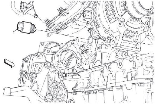
Turbocharger Coolant Feed Pipe Replacement
Special Tools
BO-38185 Hose Clamp Pliers
For equivalent regional tools, refer to Special Tools.
Removal Procedure
1. Drain the cooling system.
2. Warm Up Three-Way Catalytic Converter Replacement (2.0L LTG) - Remove.
3.
.png)
Turbocharger Coolant Feed Pipe Hollow Screw (1) - Remove.
4. Remove and DISCARD the copper washers (2).
5. Turbocharger Coolant Feed Pipe Fastener (3) - Remove [2x].
6. Remove and DISCARD the gasket (4).
7. Using the BO-38185 Hose Clamp Pliers, relocate the turbocharger coolant feed pipe hose clamp (5).
8. Turbocharger Coolant Feed Pipe (6) - Remove.
Installation Procedure
1.
.png)
Turbocharger Coolant Feed Pipe (6) - Install.
2. Using the BO-38185 Hose Clamp Pliers, install the turbocharger coolant feed pipe hose clamp (5).
3. Install a NEW gasket (4).
CAUTION: Refer to Fastener Caution.
4. Turbocharger Coolant Feed Pipe Fastener (3) - Install and tighten [2x] 10 N.m (89 lb in).
5. Install NEW copper washers (2).
6. Turbocharger Coolant Feed Pipe Hollow Screw (1) - Install and tighten35 N.m (26 lb ft).
7. Warm Up Three-Way Catalytic Converter Replacement (2.0L LTG) - Install.
8. Fill the cooling system.
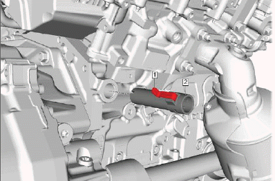
TURBOCHARGER COOLANT RETURN PIPE REPLACEMENT
Removal Procedure
1. Drain the cooling system.
2. Intake Manifold Cover - Remove.
3. Turbocharger Heat Shield - Remove.
4.
.png)
Turbocharger Coolant Return Pipe Banjo Bolt (1) - Remove.
5. Washer (2) - Remove and DISCARD [2x].
6.
.png)
Turbocharger Coolant Return Pipe Bracket Bolt (1) - Remove.
7. Clamp (2) - Loosen.
8. Turbocharger Coolant Return Pipe (4) @ Engine Coolant Air Bleed Hose (3) - Disconnect.
9. Turbocharger Coolant Return Pipe (4) - Remove.
Installation Procedure
1.
.png)
Turbocharger Coolant Return Pipe (4) - Install.
2. Turbocharger Coolant Return Pipe (4) @ Engine Coolant Air Bleed Hose (3) - Connect.
3. Clamp (2) - Install.
4. Turbocharger Coolant Return Pipe Bracket Bolt (1) - Install and hand tighten.
5.
.png)
Washer (2) - Install NEW [2x].
CAUTION: Fastener Caution
6. Turbocharger Coolant Return Pipe Banjo Bolt (1) - Install and tighten35N.m (26 lb ft).
7.
.png)
Turbocharger Coolant Return Pipe Bracket Bolt (1) - Tighten10N.m (89 lb in).
8. Turbocharger Heat Shield - Install.
9. Intake Manifold Cover - Install.
10. Fill the cooling system.
Thermostat Bypass Hose Replacement (2.0L LTG)
.png)
Preliminary Procedures
1. Drain the cooling system.
2. Radiator Inlet Hose @ Water Outlet - Remove.
- Thermostat Bypass Hose Clamp [2x]
Procedure
Hose Clamp Replacement Guidelines - Spring Type
- Thermostat Bypass Hose
Procedure
1. Radiator Inlet Hose @ Water Outlet - Install.
2. Fill the cooling system. 3. Check the cooling system for leaks.
WATER PUMP INLET PIPE REPLACEMENT (3.6L LGX)
Removal Procedure
1. Drain the cooling system.
2. Generator - Remove.
3.
.png)
Radiator Outlet Hose Clamp (1) - Disconnect.
4. Radiator Outlet Hose (2) @ Water Pump Inlet Pipe - Remove.
5. Water Pump Inlet Pipe Bolt (3) - Remove.
6.
.png)
Water Pump Inlet Pipe Bolt (1) - Remove [2x].
7. Water Pump Inlet Pipe (2) - Remove.
8. Water Pump Inlet Pipe Seal (3) - Remove and DISCARD.
Installation Procedure
1.
.png)
Water Pump Inlet Pipe Seal (3) - Install NEW.
2. Water Pump Inlet Pipe (2) - Install.
CAUTION: Refer to Fastener Caution.
3. Water Pump Inlet Pipe Bolt (1) - Install and tighten [2x] 15 N.m (11 lb ft).
4.
.png)
Water Pump Inlet Pipe Bolt (3) - Install and tighten15 N.m (11 lb ft).
5. Radiator Outlet Hose (2) @ Water Pump Inlet Pipe - Install.
6. Radiator Outlet Hose Clamp (1) - Connect.
7. Generator - Install.
8. Fill the cooling system.
9. Start the engine and check for leaks.
ENGINE COOLANT THERMOSTAT HOUSING REPLACEMENT (2.0L LTG)
.png)
Preliminary Procedure
Radiator Outlet Hose Replacement (2.0L LTG) or Radiator Outlet Hose Replacement (3.6L LGX without Engine Oil Cooler) or Radiator Outlet Hose Replacement (3.6L LGX with Engine Oil Cooler).
- Engine Coolant Thermostat Housing Bolt [2x]
CAUTION: Refer to Fastener Caution.
Tighten 10 N.m (89 lb in)
- Engine Coolant Thermostat Housing
Procedure
Install a NEW engine coolant thermostat housing seal.
ENGINE COOLANT THERMOSTAT HOUSING REPLACEMENT (3.6L LGX)
Removal Procedure
1. Drain the cooling system.
2.
.png)
Fuel Injection Fuel Rail Noise Shield (1) - Remove.
3.
.png)
Engine Coolant Air Bleed Pipe (1) - Remove.
4. Engine Rear Noise Shield - Remove.
5.
.png)
Engine Coolant Thermostat Housing Inlet Pipe Bolt (1) - Remove.
6.
.png)
Using a suitable flat bladed tool as shown, separate the engine coolant thermostat housing inlet pipe from the thermostat housing.
7.
.png)
Engine Coolant Thermostat Housing Bolt (1) - Remove [2x].
8. Engine Coolant Thermostat Housing (2) - Remove.
9. Engine Coolant Thermostat Housing Seal (3) - Remove and DISCARD.
10.
.png)
Engine Coolant Thermostat Housing Inlet Pipe O-ring Seal (1) - Remove and DISCARD.
Installation Procedure
1.
.png)
Engine Coolant Thermostat Housing Inlet Pipe O-ring Seal (1) - Install NEW.
2.
.png)
Engine Coolant Thermostat Housing Seal (3) - Install NEW.
3. Engine Coolant Thermostat Housing (2) - Install.
CAUTION: Refer to Fastener Caution.
4. Engine Coolant Thermostat Housing Bolt (1) - Install and tighten [2x] 10 N.m (89 lb in).
5.
.png)
Insert the engine coolant thermostat housing inlet pipe (1) to the thermostat housing.
6.
.png)
Engine Coolant Thermostat Housing Inlet Pipe Bolt (1) - Install and tighten 10 N.m (89 lb in).
7.
.png)
Engine Coolant Air Bleed Pipe (1) - Install.
8. Engine Rear Noise Shield - Install.
9.
.png)
Fuel Injection Fuel Rail Noise Shield (1) - Install.
10. Fill the cooling system.
11. Start the engine and check for leaks.
Engine Coolant Thermostat Housing Inlet Pipe Replacement (3.6L LGX)
Removal Procedure
1. Drain the cooling system.
2. Engine Rear Noise Shield - Remove.
3.
.png)
Radiator Inlet Hose Clamp (1) - Disengage.
4. Radiator Inlet Hose (2) - Disconnect.
5. Engine Coolant Thermostat Housing Inlet Pipe Bolt (3) - Remove.
6.
.png)
Engine Coolant Thermostat Housing Inlet Pipe (1) - Remove.
7. Engine Coolant Thermostat Housing Seal (2) - Remove and DISCARD.
Installation Procedure
1.
.png)
Engine Coolant Thermostat Housing Seal (2) - Install NEW.
2. Engine Coolant Thermostat Housing Inlet Pipe (1) - Install.
3.
.png)
CAUTION: Refer to Fastener Caution.
Engine Coolant Thermostat Housing Inlet Pipe Bolt (3) - Install and tighten10 N.m (89 lb in).
4. Radiator Inlet Hose (2) - Connect.
5. Radiator Inlet Hose Clamp (1) - Engage.
6. Engine Rear Noise Shield - Install.
7. Fill the cooling system.
8. Start the engine and check for leaks.
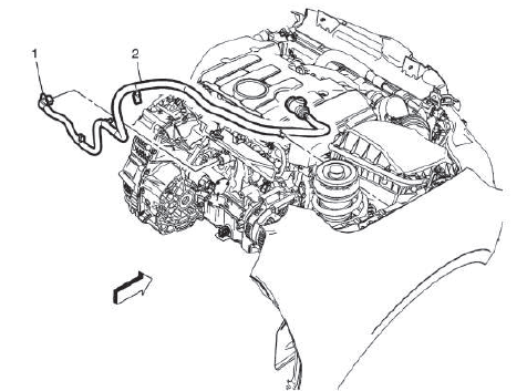
ENGINE COOLANT AIR BLEED PIPE REPLACEMENT (3.6L LGX)
Removal Procedure
1. Drain the cooling system.
2. Air Cleaner Outlet Duct - Remove.
3.
.png)
NOTE: To aid in removal of the engine air bleed pipes, separate the air bleed hose and remove the pipes individually.
NOTE: Using penetrating oil at the locations indicated by the arrows will aid in removal of the pipes from the cylinder heads.
Engine Coolant Air Bleed Hose Clamp (1) - Disengage.
4. Engine Coolant Air Bleed Hose (2) - Disconnect.
5.
.png)
Radiator Surge Tank Inlet Hose Clamp (1) - Disengage.
6. Engine Coolant Temperature Sensor Jumper Harness Retainer Clip (2) - Disconnect.
7. Engine Coolant Air Bleed Pipe Bolt (3) - Remove [2x].
8.
.png)
Engine Coolant Air Bleed Pipe (1) - Remove.
9. Engine Coolant Air Bleed Pipe O-Ring (2) - Remove and DISCARD [2x].
Installation Procedure
1.
.png)
Engine Coolant Air Bleed Pipe O-Ring (2) - Install NEW [2x].
2. Engine Coolant Air Bleed Pipe (1) - Install.
3.
.png)
CAUTION: Refer to Fastener Caution.
Engine Coolant Air Bleed Pipe Bolt (3) - Install and tighten [2x] 10 N.m (89 lb in).
4. Engine Coolant Temperature Sensor Jumper Harness Retainer Clip (2) - Connect.
5. Radiator Surge Tank Inlet Hose Clamp (1) - Engage.
6. Air Cleaner Outlet Duct - Install.
7. Fill the cooling system.
8. Start the engine and check for leaks.
ENGINE COOLANT AIR BLEED PIPE REPLACEMENT (2.0L LTG)
.png)
Preliminary Procedures
1. Turbocharger Coolant Return Pipe Replacement.
2. Positive Crankcase Ventilation Hose/Pipe/Tube Replacement.
3. Disconnect the electrical wiring harness connector from the ignition coil.
-
Radiator Surge Tank Inlet Hose Clamp
-
Engine Coolant Air Bleed Pipe Bolt
CAUTION: Refer to Fastener Caution.
Tighten 9 N.m (80 lb in)
-
Engine Coolant Air Bleed Pipe
-
Engine Coolant Air Bleed Pipe O-Ring
Procedure
Install a NEW O-ring seal.
ENGINE COOLANT AIR BLEED HOSE REPLACEMENT (3.6L LGX)
.png)
Preliminary Procedures
1. Drain the cooling system.
2. Air Cleaner Outlet Duct Replacement.
- Engine Coolant Air Bleed Hose Clamp [2x].
- Engine Coolant Air Bleed Hose.
ENGINE COOLANT AIR BLEED HOSE REPLACEMENT - AIR BLEED PIPE TO TURBOCHARGER COOLANT RETURN PIPE (2.0L LTG)
.png)
Preliminary Procedure
Remove the engine coolant air bleed pipe. Refer to Engine Coolant Air Bleed Pipe Replacement (3.6L LGX) or Engine Coolant Air Bleed Pipe Replacement (2.0L LTG).
Special Tools
BO-38185 Hose Clamp Pliers
For equivalent regional tools, refer to Special Tools.
- Engine Coolant Air Bleed Hose
NOTE: Replace hose clamps if necessary.
ENGINE COOLANT AIR BLEED HOSE REPLACEMENT - AIR BLEED PIPE TO RADIATOR SURGE TANK (2.0L LTG)
.png)
Preliminary Procedures
1. Intake Manifold Cover - Remove.
- Engine Coolant Air Bleed Hose Clip
- Engine Coolant Air Bleed Hose Clamp [2x]
Procedure
Hose Clamp Replacement Guidelines - Spring Type.
- Engine Coolant Air Bleed Hose
Procedure
1. Intake Manifold Cover - Install.
2. Check the cooling system for leaks.
WATER OUTLET REPLACEMENT (2.0L LTG)
Special Tools
BO-38185 Hose Clamp Pliers
For equivalent regional tools, refer to Special Tools.
Removal Procedure
1. Drain the cooling system. Refer to Cooling System Draining and Filling (Static) or Cooling System Draining and Filling (GE 47716).
2. Remove the intake manifold cover. Refer to Intake Manifold Cover Replacement.
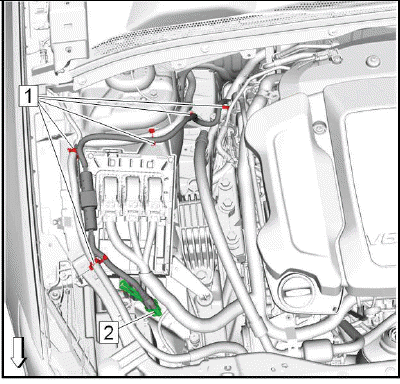
3. Reposition the engine control module and bracket without disconnecting the module electrical connectors. Refer to Engine Control Module Replacement.
4.
.png)
Disconnect the engine coolant temperature (ECT) sensor connector (3) from the water outlet (2).
5. Remove the following hoses from the water outlet:
- Radiator inlet hose (1).
- Heater inlet hose (4).
- Heater outlet hose (5).
6.
.png)
Remove the water outlet fasteners (3) and remove the water outlet (2).
7.
.png)
Remove the thermostat bypass hose (2) from the water outlet (3).
8. Discard the water outlet seal (1).
Installation Procedure
1.
.png)
Install the thermostat bypass hose (2) to the water outlet (3).
2.
.png)
Install the water outlet (2) into position with a NEW seal (1).
CAUTION: Refer to Fastener Caution.
3. Install the water outlet fasteners (3) and tighten to 12 N.m (106 lb in).
4.
.png)
Connect the engine coolant temperature (ECT) sensor connector (3) to the water outlet (2).
5. Install the following hoses to the water outlet:
- Radiator inlet hose (1).
- Heater inlet hose (4).
- Heater outlet hose (5).
6. Install the engine control module and bracket. Refer to Engine Control Module Replacement.
7. Install the intake manifold cover. Refer to Intake Manifold Cover Replacement.
8. Fill the cooling system. Refer to Cooling System Draining and Filling (Static) or Cooling System Draining and Filling (GE 47716).
9. Start the engine and check for coolant leaks.
THERMOSTAT BYPASS PIPE REPLACEMENT (2.0L LTG)
Removal Procedure
1. Drain the cooling system.
2. Exhaust Manifold Brace - Remove.
3.
.png)
Thermostat Bypass Hose Clamp (1) - Disengage.
4. Engine Oil Cooler Inlet Hose Clamp (2) - Disengage.
5.
.png)
Thermostat Bypass Pipe Bolt (1) - Remove [2x].
6. Thermostat Bypass Pipe (2) - Remove.
7. Thermostat Bypass Pipe Gasket (3) - Remove and DISCARD.
Installation Procedure
1.
.png)
NOTE: Install a NEW thermostat bypass pipe gasket.
Thermostat Bypass Pipe Gasket (3) - Install.
2. Thermostat Bypass Pipe (2) - Install.
CAUTION: Refer to Fastener Caution.
3. Thermostat Bypass Pipe Bolt (1) - Install and tighten [2x] 10 N.m (89 lb in).
4.
.png)
Engine Oil Cooler Inlet Hose Clamp (2) - Engage.
5. Thermostat Bypass Hose Clamp (1) - Engage.
6. Exhaust Manifold Brace - Install.
7. Fill the cooling system.
8. Start the engine and check for leaks.
HEATER INLET AND OUTLET PIPE REPLACEMENT
.png)
Preliminary Procedures
1. Drain the cooling system.
2. Air Cleaner Assembly Replacement.
- Heater Hose Clamp [2x]
- Heater Inlet and Outlet Pipe Bolt [2x]
CAUTION: Refer to Fastener Caution.
Tighten 9 N.m (80 lb in)
- Heater Inlet and Outlet Pipe
- Heater Inlet and Outlet Pipe Gasket
Water Pump Pulley Replacement (3.6L LGX)
.png)
Preliminary Procedure
Drive Belt Replacement.
- Water Pump Pulley Bolt [4x]
CAUTION: Refer to Fastener Caution.
Tighten 10 N.m (89 lb in)
- Water Pump Pulley
Procedure
1. Install the EN-46104 Water Pump Pulley Holding Tool onto the water pump pulley mounting holes.
2. Remove the water pump pulley bolts.
3. Remove the EN-46104 Water Pump Pulley Holding Tool from the water pump pulley.
Special Tools
EN-46104 Water Pump Pulley Holding Tool
For equivalent regional tools, refer to Special Tools.
WATER PUMP REPLACEMENT (3.6L LGX)
Removal Procedure
1. Drain the cooling system.
2. Drive Belt Tensioner - Remove.
3. Drive Belt Idler Pulley - Remove.
4. Water Pump Pulley - Remove.
5.
.png)
Engine Front Cover Bolt (1) - Remove [9x].
6. Water Pump Bolt (2) - Remove [5x].
7.
.png)
Water Pump (1) - Remove.
8. Water Pump Gasket (2) - Remove and DISCARD.
9. Carefully clean the water pump sealing surfaces.
Installation Procedure
1.
.png)
Water Pump Gasket (2) - Install NEW.
2. Water Pump (1) - Install.
3.
.png)
Water Pump Bolt (2) - Install and hand tighten - Hand tighten [5x].
4. Engine Front Cover Bolt (1) - Install and hand tighten [9x].
.png)
Fig. 1: Water Pump Bolts Tightening Sequence
5.
CAUTION: Refer to Fastener Caution.
Tighten the water pump bolts in the sequence shown to 15 N.m (11 lb ft).
6. Water Pump Pulley - Install.
7. Drive Belt Idler Pulley - Install.
8. Drive Belt Tensioner - Install.
9. Fill the cooling system.
10. Start the engine and check for leaks.
WATER PUMP REPLACEMENT (2.0L LTG)
Removal Procedure
1. Drain the cooling system.
2. Drive Belt - Remove.
3. Turbocharger - Remove.
4.
.png)
Wiring Harness Clip (4) - Remove.
5. Wiring Harness (1) - Position aside.
6. Clamp (2) - Loosen.
7. Radiator Outlet Hose (3) - Disconnect.
8.
.png)
Thermostat Bypass Pipe Bolt (1) - Remove [2x].
9.
.png)
Water Pump Bolt (2) - Remove [3x].
10. Water Pump (3) - Remove.
11. Water Pump Seal (1) - Remove and DISCARD.
12.
.png)
Thermostat Bypass Pipe Gasket (1) - Remove and DISCARD.
Installation Procedure
1.
.png)
Thermostat Bypass Pipe Gasket (1) - Install NEW.
2.
.png)
Water Pump Seal (1) - Install NEW.
3. Water Pump (3) - Install.
CAUTION: Refer to: Fastener Caution
4. Water Pump Bolt (2) - Install and hand tighten [3x].
5.
.png)
Thermostat Bypass Pipe Bolt (1) - Install and hand tighten [2x].
6.
.png)
Water Pump Bolt (2) - Tighten [3x] 25N.m (18 lb ft).
7.
.png)
Thermostat Bypass Pipe Bolt (1) - Tighten [2x] 10N.m (89 lb in).
8.
.png)
Radiator Outlet Hose (3) - Connect.
9. Clamp (2) - Install.
10. Wiring Harness (1) - Reposition.
11. Wiring Harness Clip (4) - Install.
12. Turbocharger - Install.
13. Drive Belt - Install.
14. Fill the cooling system.
Auxiliary Water Pump Replacement (FWD)
Removal Procedure
1. Drain the cooling system.
2.
.png)
Steering Gear Heat Shield (2) - Remove.
3.
.png)
Heater Outlet Hose Clamp (1) - Disengage.
4. Heater Outlet Hose (2) @ Auxiliary Water Pump - Remove.
5.
.png)
Heater Coolant Pump Hose Clamp (1) - Disengage.
6. Heater Coolant Pump Hose (2) @ Auxiliary Water Pump - Remove.
7. Electrical Connector @ Auxiliary Water Pump - Disconnect.
8.
.png)
Auxiliary Water Pump Bolt (1) - Remove.
9.
.png)
Auxiliary Water Pump (1) - Remove.
Installation Procedure
1.
.png)
Auxiliary Water Pump (1) - Install.
2.
.png)
CAUTION: Refer to Fastener Caution.
Auxiliary Water Pump Bolt (1) - Install and tighten 9 N.m (80 lb in).
3. Electrical Connector @ Auxiliary Water Pump - Connect.
4.
.png)
Heater Coolant Pump Hose (2) @ Auxiliary Water Pump - Install.
5. Heater Coolant Pump Hose Clamp (1) - Engage.
6.
.png)
Heater Outlet Hose (2) @ Auxiliary Water Pump - Install.
7. Heater Outlet Hose Clamp (1) - Engage.
8.
.png)
Steering Gear Heat Shield (2) - Install.
9. Fill the cooling system to the proper level.
10. Start the engine and check for coolant leaks.
AUXILIARY WATER PUMP REPLACEMENT (AWD)
Removal Procedure
1. Drain the cooling system.
2. Electrical Connector @ Auxiliary Water Pump - Disconnect.
3.
.png)
Auxiliary Water Pump Bolt (1) - Remove.
4. Lower the vehicle.
NOTE: Note the heater hose routing for proper installation.
5. Reposition the auxiliary water pump to access the Heater Hoses.
6.
.png)
Heater Coolant Pump Hose (2) @ Auxiliary Water Pump - Remove.
7.
.png)
Heater Outlet Hose (2) @ Auxiliary Water Pump - Remove.
8.
.png)
Auxiliary Water Pump (1) - Remove.
Installation Procedure
1.
.png)
Heater Outlet Hose (2) @ Auxiliary Water Pump - Install.
2.
.png)
Heater Coolant Pump Hose (2) @ Auxiliary Water Pump - Install.
3. Reposition the auxiliary water pump.
4. Raise the vehicle.
5.
.png)
CAUTION: Refer to Fastener Caution.
Auxiliary Water Pump Bolt (1) - Install and tighten 9 N.m (80 lb in).
6. Electrical Connector @ Auxiliary Water Pump - Connect.
7. Fill the cooling system to the proper level.
8. Start the engine and check for coolant leaks.
Radiator Drain Cock Replacement
.png)
Preliminary Procedures
1. Raise and support the vehicle. Lifting and Jacking the Vehicle.
2. Place a drain pan under the drain cock.
- Radiator Drain Cock
Procedure
- Fill the cooling system to the proper level.
- Start the engine and check for coolant leaks.
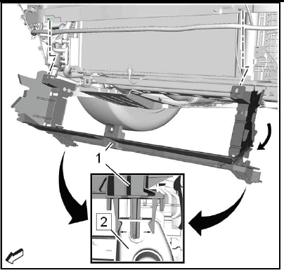
RADIATOR REPLACEMENT (2.0L LTG)
Removal Procedure
1. Drain the cooling system.
2.
.png)
Front Bumper Fascia (1) - Remove.
3.
.png)
Hood Primary Latch Mount Panel Bracket (3) - Remove.
4. Recover the refrigerant.
5.
.png)
Air Conditioning Condenser & Air Conditioning Condenser Bracket (1) - Remove.
6.
.png)
Charge Air Cooler (2) - Remove.
7.
.png)
Transmission Fluid Cooler Inlet and Outlet Pipe Retainer (1) @ Radiator - Remove [2x].
8. Transmission Fluid Cooler Inlet and Outlet Pipe Retainer (2) - Unclip.
9.
.png)
Transmission Fluid Cooler Inlet Pipe (1) @ Radiator - Remove.
10.
.png)
Transmission Fluid Cooler Outlet Pipe (1) @ Radiator - Remove.
11.
.png)
Electrical Connector (3) @ Air Conditioning Condenser Hose (2) - Disconnect.
12. Retainer (1, 4) - Unclip [2x].
13.
.png)
Ground Cable Nut (1) - Remove.
14. Ground Cable (2) - Remove.
15.
.png)
Electrical Connector (1) - Disconnect [2x].
16. Retainer (2) - Unclip.
17.
.png)
Clip (5) - Remove.
18. Disconnect the electrical connector. (4).
19. Clamp (6) - Remove.
20. Radiator Inlet Hose (3) - Remove.
21. Radiator Upper Bracket Bolt (1) - Remove.
22. Radiator Upper Bracket Nut (2) - Remove.
23. Radiator Upper Bracket (7) - Remove.
24.
.png)
Clamp (2) - Remove.
25. Radiator Outlet Hose (1) @ Radiator (3) - Remove.
26.
.png)
Radiator Upper Bracket Nut (1) - Remove.
27. Radiator Upper Bracket Bolt (2) - Remove.
28. Radiator Upper Bracket (3) - Remove.
29.
.png)
Radiator Assembly (1) - Remove.
30. Radiator Lower Insulator (2) - Remove [2x].
31.
.png)
Engine Coolant Fan Shroud Bolt (3) - Remove [2x].
32. Engine Coolant Fan (2) @ Radiator (1) - Remove.
33.
.png)
Radiator Upper Bracket (1) - Remove [2x] - Unlock the retaining tabs in direction of the arrow.
34. Radiator Lower Bracket (4) - Remove [2x] - Unlock the retaining tabs in direction of the arrow.
35. Radiator Sleeve (3) - Remove - Unlock the retaining tabs in direction of the arrow.
36. Remove the 4 radiator nuts (2, 5).
Installation Procedure
1.
.png)
Install the 4 radiator nuts (2, 5).
2. Radiator Upper Bracket (1) - Install [2x].
3. Radiator Lower Bracket (4) - Install [2x].
4. Radiator Sleeve (3) - Install.
5.
.png)
Engine Coolant Fan (2) @ Radiator (1) - Install.
CAUTION: Fastener Caution.
6. Engine Coolant Fan Shroud Bolt (3) - Install and tighten [2x] 5.1N.m (45 lb in).
7.
.png)
Radiator Lower Insulator (2) - Install [2x].
8. Radiator Assembly (1) - Install.
9.
.png)
Radiator Upper Bracket (3) - Install.
10. Radiator Upper Bracket Bolt (2) - Install and tighten7N.m (62 lb in).
11. Radiator Upper Bracket Nut (1) - Install and tighten7N.m (62 lb in).
12.
.png)
Radiator Outlet Hose (1) @ Radiator (3) - Install.
13. Clamp (2) - Install.
14.
.png)
Radiator Upper Bracket (7) - Install.
15. Radiator Upper Bracket Bolt (1) - Install and tighten7N.m (62 lb in).
16. Radiator Upper Bracket Nut (2) - Install and tighten7N.m (62 lb in).
17. Radiator Inlet Hose (3) - Install.
18. Clamp (6) - Install.
19. Connect the electrical connector. (4).
20. Clip (5) - Install [2x].
21.
.png)
Retainer (2) - Install.
22. Electrical Connector (1) - Connect [2x].
23.
.png)
Ground Cable (2) - Install.
24. Ground Cable Nut (1) - Install and tighten9N.m (80 lb in).
25.
.png)
Electrical Connector (3) @ Air Conditioning Condenser Hose (2) - Connect.
26. Retainer (1, 4) - Install [2x].
27.
.png)
Transmission Fluid Cooler Outlet Pipe (1) @ Radiator - Install.
28.
.png)
Transmission Fluid Cooler Inlet Pipe (1) @ Radiator - Install.
29.
.png)
Transmission Fluid Cooler Inlet and Outlet Pipe Retainer (1) @ Radiator - Install [2x].
30. Transmission Fluid Cooler Inlet and Outlet Pipe Retainer (2) - Install.
31.
.png)
Charge Air Cooler (2) - Install.
32.
.png)
Air Conditioning Condenser & Air Conditioning Condenser Bracket (1) - Install.
33.
.png)
Hood Primary Latch Mount Panel Bracket (3) - Install.
34. Recharge the refrigerant. Refrigerant Recovery and Recharging (R-1234yf).
35.
.png)
Front Bumper Fascia (1) - Install.
36. Fill the cooling system.
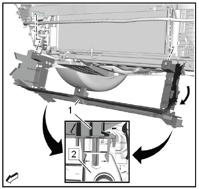
Radiator Replacement (3.6L LGX)
Removal Procedure
1. Drain the cooling system.
2. Front Bumper Fascia - Remove.
3.
.png)
Hood Primary Latch Mount Panel Bracket (3) - Remove.
4. Recover the refrigerant.
5.
.png)
Air Conditioning Condenser Bracket (1) - Remove.
6. Transmission Fluid Cooler Inlet and Outlet Pipe Retainer @ Engine Cooler Fan - Remove.
7.
.png)
Transmission Fluid Cooler Inlet Pipe (1) @ Radiator - Remove.
8.
.png)
Transmission Fluid Cooler Outlet Pipe (2) @ Radiator - Remove.
9. Intake Air Duct - Remove.
10.
.png)
Remove the engine coolant fan wiring harness ground nut (1).
11. Remove the engine coolant fan wiring harness (2) from the front end upper tie bar support.
12. Retainer @ Radiator - Unclip.
13.
.png)
Electrical Connector (1) - Disconnect [2x].
14.
.png)
Clamp (4) - Disengage.
15. Radiator Inlet Hose (3) - Remove.
16. Radiator Upper Bracket (5) - Remove.
17.
.png)
Clamp (1) - Disengage.
18. Radiator Outlet Hose (2) @ Radiator - Remove.
19.
Radiator Upper Bracket (3) - Remove.
20.
.png)
Radiator Sleeve (3) - Remove.
21.
.png)
Radiator Assembly (1) - Remove.
22. Radiator Lower Insulator (2) - Remove [2x].
23.
.png)
Engine Coolant Fan Shroud Clip (1) @ Engine Coolant Fan - Remove.
24.
.png)
Engine Coolant Fan Shroud Bolt (3) - Remove [2x].
25. Engine Coolant Fan (2) @ Radiator (1) - Remove.
26.
.png)
Radiator Upper Bracket (1) - Remove [2x].
27. Radiator Lower Bracket (4) - Remove [2x].
28. Remove the 4 radiator nuts (2, 5).
Installation Procedure
1.
.png)
Install the 4 radiator nuts (2, 5).
2. Radiator Upper Bracket (1) - Install [2x].
3. Radiator Lower Bracket (4) - Install [2x].
4.
.png)
Engine Coolant Fan (2) @ Radiator (1) - Install.
CAUTION: Refer to Fastener Caution.
5. Engine Coolant Fan Shroud Bolt (3) - Install and tighten [2x] 5.1N.m (45 lb in).
6.
.png)
Engine Coolant Fan Shroud Clip (1) @ Engine Coolant Fan - Install.
7. Radiator Lower Insulator (2) - Install [2x].
8.
.png)
Radiator Assembly (1) - Install.
9.
.png)
Radiator Sleeve (3) - Install.
10.
.png)
Radiator Upper Bracket (3) - Install.
11.
.png)
Radiator Outlet Hose (2) @ Radiator - Install.
12. Clamp (1) - Engage.
13.
.png)
Radiator Upper Bracket (5) - Install.
14. Radiator Inlet Hose (3) - Install.
15. Clamp (4) - Engage.
16.
.png)
Electrical Connector (1) - Connect [2x].
17. Retainer @ Radiator - Install.
18.
.png)
Install the engine coolant fan wiring harness (2) to the front end upper tie bar support.
19. Install and tighten the engine coolant fan wiring harness ground nut (1).
20. Intake Air Duct - Install.
21.
.png)
Transmission Fluid Cooler Outlet Pipe (2) @ Radiator - Install.
22.
.png)
Transmission Fluid Cooler Inlet Pipe (1) @ Radiator - Install.
23. Transmission Fluid Cooler Inlet and Outlet Pipe Retainer @ Engine Cooler Fan - Install.
24.
.png)
Air Conditioning Condenser Bracket (1) - Install.
25.
.png)
Hood Primary Latch Mount Panel Bracket (3) - Install.
26. Recharge the refrigerant.
27. Front Bumper Fascia - Install.
28. Fill the cooling system.
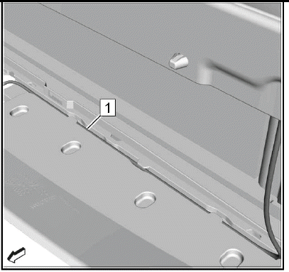
Radiator Lower Insulator Replacement
.png)
Preliminary Procedure
Radiator Replacement (2.0L LTG) or Radiator Replacement (3.6L LGX)
- Radiator Lower Insulator [2x]
RADIATOR AIR LOWER BAFFLE REPLACEMENT
Removal Procedure
1. Front Bumper Fascia - Remove.
2.
.png)
Body Wiring Harness (2) - Unclip.
3. Ambient Air Temperature Sensor (3) - Remove.
4. Radiator Air Lower Baffle Bolt (1) - Remove [2x].
5.
.png)
Wiring Harness (1) - Unclip.
6.
Radiator Air Lower Baffle (1) @ Radiator Lower Bracket (2) - Unclip [2x].
7. Rotate the radiator air lower baffle (1) a little bit clockwise that it is removed from radiator lower bracket and then move it downwards.
8. Radiator Air Lower Baffle (1) - Remove.
Installation Procedure
1.
Radiator Air Lower Baffle (1) - Install.
2. Rotate the radiator air lower baffle (1) a little bit clockwise and then move it upwards to the front bumper impact bar. Then rotate it counterclockwise to install it to the radiator lower bracket.
3. Radiator Air Lower Baffle (1) @ Radiator Lower Bracket (2) - Install [2x].
4.
Wiring Harness (1) - Install.
5.
Body Wiring Harness (2) - Install.
6. Ambient Air Temperature Sensor (3) - Install.
CAUTION: Fastener Caution.
7. Radiator Air Lower Baffle Bolt (1) - Install and tighten 2.5N.m (22 lb in) [2x].
8. Front Bumper Fascia - Install.
RADIATOR AIR SIDE UPPER BAFFLE REPLACEMENT - LEFT SIDE
Preliminary Procedures
1. Remove the radiator air upper baffle.
2. Remove the front bumper fascia.
- Radiator Air Side Upper Baffle - Left Side
Procedure
- Install the front bumper fascia.
- Install the radiator air upper baffle.
RADIATOR AIR SIDE UPPER BAFFLE REPLACEMENT - RIGHT SIDE
Preliminary Procedures
1. Remove the radiator air upper baffle.
2. Remove the front bumper fascia.
- Radiator Air Side Upper Baffle - Right Side
Procedure
- Install the front bumper fascia.
- Install the radiator air upper baffle.
RADIATOR AIR UPPER BAFFLE REPLACEMENT
- Retainer [7x]
- Radiator Air Upper Baffle
COOLANT HEATER REPLACEMENT (2.0L LTG)
Preliminary Procedure
1. Drain the cooling system. Refer to Cooling System Draining and Filling (Static) or Cooling System Draining and Filling (GE 47716).
2. Remove the starter. Refer to Starter Replacement (2.0L LTG) or Starter Replacement (3.6L LGX).
- Engine Coolant Heater
CAUTION: Refer to Component Fastener Tightening Caution.
Procedure
Disconnect the engine coolant heater cord.
Tighten 50 N.m (37 lb ft)
COOLANT HEATER REPLACEMENT (3.6L LGX)
Preliminary Procedure
Lifting and Jacking the Vehicle.
- Engine Coolant Heater Clip
- Engine Coolant Heater
Procedure
Disconnect the coolant heater cord.
COOLANT HEATER CORD REPLACEMENT (2.0L LTG)
Preliminary Procedure
Raise and support the vehicle. Refer to Lifting and Jacking the Vehicle.
- Coolant Heater Connector
- Coolant Heater Cord
NOTE: Observe how the coolant heater cord was routed within the engine compartment.
COOLANT HEATER CORD REPLACEMENT (3.6L LGX)
Removal Procedure
1.
Electrical Connector (2) - Disconnect.
2. Coolant Heater Cord Clip (1) - Unclip [5x].
3.
Coolant Heater Cord Clip (2) - Unclip [4x].
4. Electrical Connector (3) - Disconnect.
5. Coolant Heater Cord (1) - Remove.
Installation Procedure
1.
Coolant Heater Cord (1) - Install.
2. Electrical Connector (3) - Connect.
3. Coolant Heater Cord Clip (2) - Install [4x].
4.
Coolant Heater Cord Clip (1) - Install [5x].
5. Electrical Connector (2) - Connect.
READ NEXT:
 Description and Operation
Cooling Fan Description and Operation
System Overview
The engine cooling fan system consists of 2 electric cooling fans and 3 fan
relays. The cooling fan relays
are arranged in a series/parallel (S/P
Firing Order and Cylinder Identification
NOTE: This information is intended as a quick reference for firing
order and
cylinder identification only. The information provided covers many
vehicles and may include some information that does not
SEE MORE:
Collision Damage Repair
If the vehicle is involved in a
collision and it is damaged, have the
damage repaired by a qualified
technician using the proper
equipment and quality replacement
parts. Poorly performed collision
repairs diminish the vehicle resale
value, and safety performance can
be compromised in subsequent
coll
Camshaft
CLEANING & INSPECTION
NOTE: Examples used in this article are general in nature and do not
necessarily
relate to a specific engine or system. Illustrations and procedures have
been chosen to guide mechanic through engine overhaul process.
Descriptions of processes of cleaning, inspection, asse
