Opel Insignia: Timing Chains & Belts
TIMING CHAINS
NOTE: Examples used in this article are general in nature and do not necessarily relate to a specific engine or system. Illustrations and procedures have been chosen to guide mechanic through engine overhaul process.
Descriptions of processes of cleaning, inspection, assembly and machine shop practice are included.
Always refer to appropriate engine overhaul article, if available, in the ENGINES section for complete overhaul procedures and specifications for the vehicle being repaired.
Timing chains will stretch during operation. Limits are placed upon amount of stretch before replacement is required. Timing chain stretch will alter ignition timing and valve timing.
To check timing chain stretch, rotate crankshaft to eliminate slack from one side of timing chain. Mark reference point on cylinder block. Rotate crankshaft in opposite direction to eliminate slack from remaining side of timing chain. Force other side of chain outward and measure distance between reference point and timing chain. See Fig. 23. Replace timing chain and gears if not within specification.
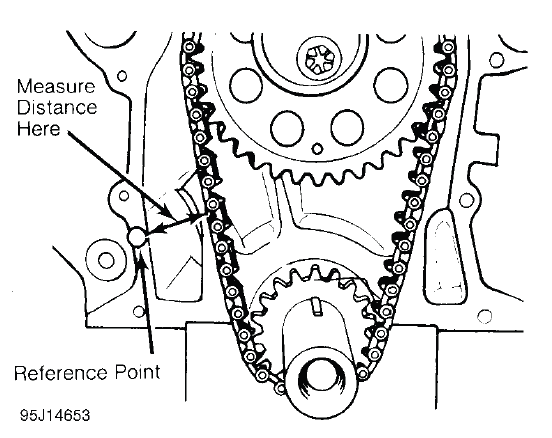
Fig. 23: Measuring Timing Chain Stretch
Timing chains must be installed so timing marks on camshaft gear and crankshaft gear are aligned according to manufacturer. See Fig. 24.
.png)
Fig. 24: Typical Gear Timing Mark Alignment
TIMING BELTS
NOTE: Examples used in this article are general in nature and do not necessarily relate to a specific engine or system. Illustrations and procedures have been chosen to guide mechanic through engine overhaul process.
Descriptions of processes of cleaning, inspection, assembly and machine shop practice are included.
Always refer to appropriate engine overhaul article, if available, in the ENGINES section for complete overhaul procedures and specifications for the vehicle being repaired.
Cogged tooth belts are commonly used on overhead cam engines. Inspect belt teeth for rounded corners or cracking. Replace belt if it is cracked, damaged, missing teeth or oil soaked.
Used timing belt must be installed in original direction of rotation. Inspect all sprocket teeth for wear.
Replace all worn sprockets. Sprockets are marked for timing purposes. Engine is positioned so that crankshaft sprocket mark will be upward. Camshaft sprocket is aligned with reference mark on cylinder head or timing belt cover and then timing belt can be installed. See Fig. 25.
.png)
Fig. 25: Typical Camshaft Belt Sprocket Alignment
TENSION ADJUSTMENT
NOTE: Examples used in this article are general in nature and do not necessarily relate to a specific engine or system. Illustrations and procedures have been chosen to guide mechanic through engine overhaul process.
Descriptions of processes of cleaning, inspection, assembly and machine shop practice are included.
Always refer to appropriate engine overhaul article, if available, in the ENGINES section for complete overhaul procedures and specifications for the vehicle being repaired.
If guide rails are used with spring loaded tensioners, ensure at least half of original rail thickness remains. Spring loaded tensioner should be inspected for damage.
Ensure all timing marks are aligned. Adjust belt tension using manufacturer's recommendations. Belt tension may require checking using tension gauge. See Fig. 26.
.png)
Fig. 26: Adjusting Typical Timing Belt Tension
READ NEXT:
 Timing Gears
TIMING GEAR BACKLASH & RUNOUT
NOTE: Examples used in this article are general in nature and do not
necessarily
relate to a specific engine or system. Illustrations and procedures have
been chosen
Oil Pump
ROTOR TYPE
NOTE: Examples used in this article are general in nature and do not
necessarily
relate to a specific engine or system. Illustrations and procedures have
been chosen to guide mechanic thro
Break-In Procedure
ENGINE PRE-OILING
NOTE: Examples used in this article are general in nature and do not
necessarily
relate to a specific engine or system. Illustrations and procedures have
been chosen to guide mechan
SEE MORE:
Technical Data
Vehicle Identification
Vehicle Identification
Number (VIN)
This legal identifier is in the front
corner of the instrument panel, on
the driver side of the vehicle. It can
be seen through the windshield from
outside. The Vehicle Identification
Number (VIN) also appears on the
Vehicle Certification
Climate Control Systems
Dual Automatic Climate
Control System
The climate control buttons on the center stack and on the climate control
display are used to adjust the heating, cooling, and ventilation.
Center Stack Climate Controls
Driver and Passenger
Temperature Displays
Driver and Passenger
Temperature Controls
