Opel Insignia: Diagnostic Information and Procedures
DTC P0218
Diagnostic Instructions
- Perform the Diagnostic System Check prior to using this diagnostic procedure: Refer to Diagnostic System Check - Vehicle
- Review the description of Strategy Based Diagnosis: Refer to Strategy Based Diagnosis
- An overview of each diagnostic category can be found here: Refer to Diagnostic Procedure Instructions
DTC Descriptor
DTC P0218
Transmission Fluid Overtemperature - Hydraulic/Mechanical Problem
Circuit/System Description
For an overview of the component/system, refer to Electronic Component Description The transmission control module monitors the transmission fluid temperature sensor to determine an overtemperature condition.
Conditions for Running the DTC
Condition 1
- DTC P0711, P0712, P0713 = Not set
- Ignition Voltage=9 to 32 V
- Vehicle Speed=Less than 180 km/h (112 MPH)
Frequency the DTC runs=Continuously - After the running conditions are met
Condition 2
- DTC P0711, P0712, P0713 = Not set
- Ignition Voltage=9 to 32 V
- Vehicle Speed=Greater than 180 km/h (112 MPH)
Frequency the DTC runs=Continuously - After the running conditions are met
Conditions for Setting the DTC
Condition 1
Transmission Fluid Temperature=Warmer than 150ºC (302ºF) - For greater than 10 s
Condition 2
Transmission Fluid Temperature=Warmer than 150ºC (302ºF) - For greater than 60 s
Actions Taken When the DTC Sets
DTCs listed in the DTC Descriptor Category=Type C DTC
Driver Information Display=Transmission Hot - Idle Engine
Conditions for Clearing the DTC
DTCs listed in the DTC Descriptor Category=Type C DTC
Diagnostic Aids
Obtain additional information from the customer to determine if the vehicle has been modified, damaged or operated in any of the following conditions, which can cause the transmission to overheat:
- Driving in hot climates
- Driving in extreme off-road conditions
- Tow/haul capacity exceeded
- Towing in the incorrect gear
Reference Information
DTC Type: Reference
Refer to Powertrain Diagnostic Trouble Code (DTC) Type Definitions
Scan Tool: Reference
Refer to Control Module: References
Circuit/System Verification
1. Verify the scan tool Freeze Frame/Failure Records parameter: ECT Sensor=Colder than 125ºC (257ºF)
- If 125ºC (257ºF) or warmer
Refer to: Engine Overheating
- Go to next step: If colder than 125ºC (257ºF)
2. Verify the condition does not exist: Incorrect fluid level or condition - Transmission - Refer to Transmission Fluid Level and Condition Check
- If a condition exists
Repair or replace as necessary.
- Go to next step: If no condition exists
3. Verify the condition does not exist: Overheating - Transmission - Refer to: Transmission Overheats
- If a condition exists
Repair or replace as necessary.
- Go to next step: If no condition exists
4. Operate the vehicle within the Conditions for Running the DTC. You may also operate the vehicle within the conditions that you observed from the Freeze Frame/Failure Records data.
Verify the DTC does not set.
- If any DTC is set
Refer to: Diagnostic Trouble Code (DTC) List - Vehicle
- Go to next step: If no DTC is set
5. All OK.
Repair Instructions
Perform the Diagnostic Repair Verification after completing the repair: Refer to Diagnostic Repair Verification
- Refer to Transmission Fluid Drain and Fill
- For control module replacement, programming, and setup: Refer to Control Module: References
DTC P0601, P0602, P0603, or P0604
Diagnostic Instructions
- Perform the Diagnostic System Check prior to using this diagnostic procedure: Refer to Diagnostic System Check - Vehicle
- Review the description of Strategy Based Diagnosis: Strategy Based Diagnosis
- An overview of each diagnostic category can be found here: Refer to Diagnostic Procedure Instructions
DTC Descriptor
DTC P0601
Control Module Read Only Memory Performance
DTC P0602
Control Module Not Programmed
DTC P0603
Control Module Long Term Memory Reset
DTC P0604
Control Module Random Access Memory Performance
Circuit/System Description
For an overview of the component/system, refer to Electronic Component Description This diagnostic applies to microprocessor integrity conditions within the control module. This diagnostic also checks if the control module is not programmed, or is programmed incorrectly.
Conditions for Running the DTC
Ignition Voltage=On
Frequency the DTC runs=Continuously - After the running conditions are met
Conditions for Setting the DTC
P0601
ROM Malfunction
P0602
Programming Malfunction
P0603
EEPROM Performance/Malfunction
P0604
RAM Malfunction
Actions Taken When the DTC Sets
DTCs listed in the DTC Descriptor Category=Type A DTC
Conditions for Clearing the DTC
DTCs listed in the DTC Descriptor Category=Type A DTC
Reference Information
Schematic: Reference
Refer to Automatic Transmission Controls Wiring Schematics
Connector End View: Reference
Refer to Component Connector End View Index
Component View: Reference
Refer to Disassembled Views
Electrical Information: Reference
- Refer to Circuit Testing
- Refer to Connector Repairs
- Refer to Testing for Intermittent Conditions and Poor Connections
- Refer to Wiring Repairs
DTC Type: Reference
Refer to Powertrain Diagnostic Trouble Code (DTC) Type Definitions
Scan Tool: Reference
Refer to Control Module: References
Circuit/System Verification
1. Ignition - On / Vehicle - In Service Mode
2. Verify DTC P0601, P0602, P0603, P0604 is not set.
- If the DTC is set
- Perform all necessary programming and setup procedures for the control module:K71 Transmission Control Module
- Verify the DTC does not set.
- If the DTC sets - Replace the component:K71 Transmission Control Module
- Go to next step: If the DTC is not set
- All OK.
- Go to next step: If the DTC is not set
3. All OK.
Repair Instructions
Perform the Diagnostic Repair Verification after completing the repair: Refer to Diagnostic Repair Verification
For control module replacement, programming, and setup: Refer to Control Module: References
DTC P0606, P177F, P2637, or P2638
Diagnostic Instructions
- Perform the Diagnostic System Check prior to using this diagnostic procedure: Refer to Diagnostic System Check - Vehicle
- Review the description of Strategy Based Diagnosis: Strategy Based Diagnosis
- An overview of each diagnostic category can be found here: Refer to Diagnostic Procedure Instructions
DTC Descriptor
DTC P0606
Control Module Processor Performance
DTC P177F
Detected Gear Incorrect
DTC P2637
Torque Increase Calculation Malfunction
DTC P2638
Breaking Torque Calculation Malfunction
Circuit/System Description
For an overview of the component/system, refer to Electronic Component Description
Conditions for Running the DTC
P0606Condition 1
Engine=Running - For greater than 10 min
Frequency the DTC runs=Continuously - After the running conditions are met
Condition 2
K71 Transmission Control Module=During control module power down
Frequency the DTC runs=Continuously - After the running conditions are met
P177F
DTC P0606 = Not set
Frequency the DTC runs=Continuously - After the running conditions are met
P2637
Engine=Running
Frequency the DTC runs=Continuously - After the running conditions are met
P2638
Ignition=On
Frequency the DTC runs=Continuously - After the running conditions are met
Conditions for Setting the DTC
P0606Condition 1
K71 Transmission Control Module=Internal Malfunction
Condition 2
Pressure Control Solenoid Valve=Commanded state does not match the actual state
P177F
Commanded gear=Incorrect - Engine Overspeed
P2637
Requested Torque Signal=Greater than a predefined threshold - For greater than 1 s
P2638
Automatic Braking Torque=Greater than a predefined threshold
Actions Taken When the DTC Sets
DTCs listed in the DTC Descriptor Category=Type A DTC - Exceptions listed below
DTC P2637=Type B
One or more of the following may occur:
- K71 Transmission Control Module=Reset
- Transmission gear allowed=3rd Gear
- TCM Requested Torque=0 Nm (0 lb ft)
Conditions for Clearing the DTC
DTCs listed in the DTC Descriptor Category=Type A - Exceptions listed below
DTC P2637=Type B
Reference Information
Schematic: Reference
Refer to Automatic Transmission Controls Wiring Schematics
Connector End View: Reference
Refer to Component Connector End View Index
Component View: Reference
Refer to Disassembled Views
Electrical Information: Reference
- Refer to Circuit Testing
- Refer to Connector Repairs
- Refer to Testing for Intermittent Conditions and Poor Connections
- Refer to Wiring Repairs
DTC Type: Reference
Refer to Powertrain Diagnostic Trouble Code (DTC) Type Definitions
Scan Tool: Reference
Refer to Control Module: References
Circuit/System Verification
1. Ignition - On / Vehicle - In Service Mode
2. Verify DTC P0606, P177F, P2637, P2638 is not set.
- If the DTC is set
- Perform all necessary programming and setup procedures for the control module:K71 Transmission Control Module
- Verify the DTC does not set.
- If the DTC sets - Replace the component:K71 Transmission Control Module
- Go to next step: If the DTC is not set
- All OK.
- Go to next step: If the DTC is not set
3. All OK.
Repair Instructions
Perform the Diagnostic Repair Verification after completing the repair: Refer to Diagnostic Repair Verification.
For control module replacement, programming, and setup: Refer to Control Module: References.
DTC P0657
Diagnostic Instructions
- Perform the Diagnostic System Check prior to using this diagnostic procedure: Diagnostic System Check - Vehicle
- Review the description of Strategy Based Diagnosis: Strategy Based Diagnosis
- An overview of each diagnostic category can be found here: Diagnostic Procedure Instructions
DTC Descriptor
DTC P0657
Actuator High Control Circuit Group 1
Circuit/System Description
For an overview of the component/system, refer to Electronic Component Description This diagnostic applies to microprocessor integrity conditions within the control module. This diagnostic also checks if the control module is not programmed, or is programmed incorrectly.
Conditions for Running the DTC
K71 Transmission Control Module=Communication Enabled
Conditions for Setting the DTC
K71 Transmission Control Module=Internal Malfunction
Actions Taken When the DTC Sets
DTCs listed in the DTC Descriptor Category=Type A DTC
Conditions for Clearing the DTC
DTCs listed in the DTC Descriptor Category=Type A DTC
Reference Information
Schematic: Reference
Refer to Automatic Transmission Controls Wiring Schematics
Connector End View: Reference
Refer to Component Connector End View Index
Component View: Reference
Refer to Disassembled Views
Electrical Information: Reference
- Refer to Circuit Testing
- Refer to Connector Repairs
- Refer to Testing for Intermittent Conditions and Poor Connections
- Refer to Wiring Repairs
DTC Type: Reference
Refer to Powertrain Diagnostic Trouble Code (DTC) Type Definitions
Scan Tool: Reference
Refer to Control Module: References
Circuit/System Verification
1. Ignition - On / Vehicle - In Service Mode
2. Verify DTC P0657 is not set.
- If the DTC is set
- Perform all necessary programming and setup procedures for the control module:K71 Transmission Control Module
- Verify the DTC does not set.
- If the DTC sets - Replace the component:K71 Transmission Control Module
- Go to next step: If the DTC is not set
- All OK.
- Go to next step: If the DTC is not set
Repair Instructions
Perform the Diagnostic Repair Verification after completing the repair: Refer to Diagnostic Repair Verification
For control module replacement, programming, and setup: Refer to Control Module: References
DTC P0705, P0707, P0708, or P0851
Diagnostic Instructions
- Perform the Diagnostic System Check prior to using this diagnostic procedure: Refer to Diagnostic System Check - Vehicle
- Review the description of Strategy Based Diagnosis: Refer to Strategy Based Diagnosis
- An overview of each diagnostic category can be found here: Refer to Diagnostic Procedure Instructions
DTC Descriptor
NOTE: This procedure may also diagnose malfunctions that are not detected by a DTC.
DTC P0705
Transmission Range Switch Circuit
DTC P0707
Transmission Range Switch Circuit Low Voltage
DTC P0708
Transmission Range Switch Circuit High Voltage
DTC P0851
Park/Neutral Position Switch Circuit Low Voltage
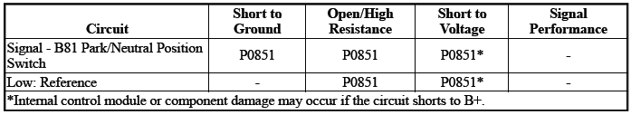
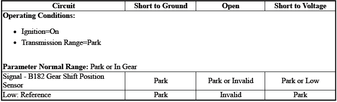
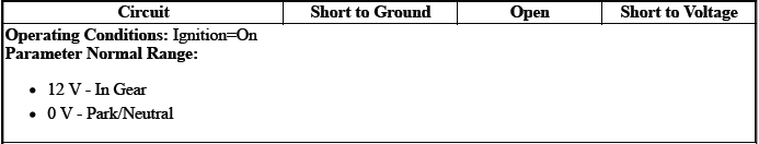
Diagnostic Fault Information
Typical Scan Tool Data
Transmission Range Switch
Park/Neutral Position Switch

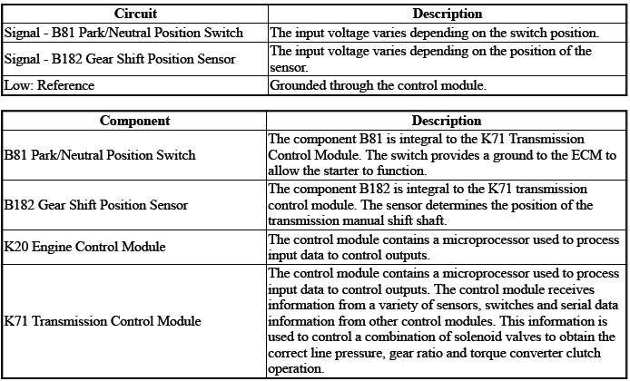
Circuit/System Description
P0705, P0707, P0708
The sensor is an input to the control module K71. The control module K71 uses the information from the sensor signal B182 to determine what transmission gear range the vehicle operator selected.
The control module uses this data, along with other data, to adjust or control the following:
- Q23 Line Pressure Control Solenoid Valve
- Q27A Pressure Control Solenoid Valve 1
- Q27B Pressure Control Solenoid Valve 2
- Q27C Pressure Control Solenoid Valve 3
- Q27D Pressure Control Solenoid Valve 4
- Q27E Pressure Control Solenoid Valve 5
- Q27F Pressure Control Solenoid Valve 6
- Q27G Pressure Control Solenoid Valve 7{ If equipped }
- Q32A Shift Solenoid Valve 1
- Q32B Shift Solenoid Valve 2
- Q39A Torque Converter Clutch Pressure Control Solenoid Valve
P0851
The sensor is an input to the control module K20.
The control module uses this data, along with other data, to adjust or control the following: KR27 Starter Relay
Conditions for Running the DTC
P0705, P0707, P0708
- DTC P0851 = Not set
- K71 Transmission Control Module=Communication Enabled
- Ignition Voltage=10 to 16 V
- Service Mode=Disabled
Frequency the DTC runs=Continuously - After the running conditions are met
P0851
- Engine Torque= Greater than 75 Nm (55 lb ft)
- Ignition Voltage=10 to 16 V
- Selector Lever Position= P or N
- Throttle Position Sensor=Greater than 8%
- Vehicle Speed=Greater than 10 km/h (6 MPH)
Frequency the DTC runs=Continuously - After the running conditions are met
Conditions for Setting the DTC
P0705
Position 1 & Position 2=Not between 4.71 and 5.29 V - For greater than 1 s & For 2 consecutive events.
P0707
Position 1orPosition 2=Less than 0.127 V - For greater than 1 s & For 2 consecutive events.
P0708
Position 1orPosition 2=Greater than 4.87 V - For greater than 1 s & For 2 consecutive events.
P0851
Engine Control Module - Vehicle Speed Detected=Greater than 10 km/h (6 MPH) & Park/Neutral Position Switch=Park/Neutral - For greater than 2 s
Actions Taken When the DTC Sets
DTCs listed in the DTC Descriptor Category=Type A DTC - Exceptions listed below - Additional actions taken:
- Transmission Learn=Disabled
- Transmission gear allowed=3rd Gear - After a stop
- Engine Cranking=Disabled
DTC P0851=Type C DTC
Engine Cranking=Disabled
Conditions for Clearing the DTC
DTCs listed in the DTC Descriptor Category=Type A DTC - Exceptions listed below
DTC P0851=Type C DTC
Reference Information
Schematic: Reference
Refer to Automatic Transmission Controls Wiring Schematics
Connector End View: Reference
Refer to Component Connector End View Index
Component View: Reference
Refer to Disassembled Views
Description and Operation
- Refer to Electronic Component Description
- Refer to Transmission General Description
Electrical Information: Reference
- Refer to Circuit Testing
- Refer to Connector Repairs
- Refer to Testing for Intermittent Conditions and Poor Connections
- Refer to Wiring Repairs
DTC Type: Reference
Refer to Powertrain Diagnostic Trouble Code (DTC) Type Definitions
Scan Tool: Reference
Refer to Control Module: References
Circuit/System Verification
1. Ignition - On / Vehicle - In Service Mode
2. Verify there are no DTCs set related to the following system/component:K173 Transmission Range Control Module - If equipped
- If any DTC is set
Refer to: Diagnostic Trouble Code (DTC) List - Vehicle
- Go to next step: If no DTC is set
3. Transmission - Park
4. Verify the scan tool parameter: Park/Neutral Position Switch@K20 Engine Control Module=Park
- If not the specified state
Refer to Circuit/System Testing
- Go to next step: If the specified state
5. Transmission - Neutral - Brake Applied
6. Verify the scan tool parameter:Park/Neutral Position Switch@K20 Engine Control Module=Neutral
- If not the specified state
Refer to Circuit/System Testing
7. Transmission - Park
8. Verify the scan tool parameter: Transmission Range Switch@K71 Transmission Control Module=Park
- If not the specified state
Replace the component: K71 Transmission Control Module
- Go to next step: If the specified state
9. Operate the component: S3 Transmission Shift Lever
Verify the scan tool parameter: Transmission Range Switch=Matches the selector lever position
- If not the specified state
Replace the component:K71 Transmission Control Module
- Go to next step: If the specified state
10. Operate the vehicle within the Conditions for Running the DTC. You may also operate the vehicle within the conditions that you observed from the Freeze Frame/Failure Records data.
Verify the DTC does not set.
- If the DTC sets
Refer to Circuit/System Testing
- Go to next step: If the DTC is not set
11. All OK.
Circuit/System Testing
NOTE: Circuit/System Verification must be performed before proceeding with Circuit/System Testing.
1. Ignition/Vehicle & All vehicle systems - Off.
2. Disconnect the electrical connector:X1 @K71 Transmission Control Module.
3. Ignition - On / Vehicle - In Service Mode.
4. Test for greater than 9 V between the test points: Signal circuit terminal 5 & Ground.
- If less than 9 V
- Disconnect the electrical connector:X1@K20 Engine Control Module
- Test for infinite resistance between the test points: Signal circuit
terminal 5@Component harness &
Ground
- If less than infinite resistance
Repair the short to ground on the circuit.
- Go to next step: If infinite resistance
- If less than infinite resistance
- Test for less than 2 ohms between the test points:
- If 2 ohms or greater
Repair the open/high resistance in the circuit.
- If less than 2 ohms
Replace the component:K20 Engine Control Module
- If 2 ohms or greater
- Go to next step: If greater than 9 V
5. Ignition/Vehicle - Off.
6. Test for less than 1 V between the test points: Signal circuit terminal 5@Component harness & Ground.
- If 1 V or greater
Repair the short to voltage on the circuit.
- Go to next step: If less than 1 V
7. Test or replace the component: Park/Neutral Position Switch
Repair Instructions
Perform the Diagnostic Repair Verification after completing the repair: Refer to Diagnostic Repair Verification
- Refer to Transmission Control Module Replacement
- For control module replacement, programming, and setup: Refer to Control Module: References
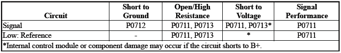
DTC P0711-P0713
Diagnostic Instructions
- Perform the Diagnostic System Check prior to using this diagnostic procedure: Refer to Diagnostic System Check - Vehicle
- Review the description of Strategy Based Diagnosis: Strategy Based Diagnosis
- An overview of each diagnostic category can be found here: Refer to Diagnostic Procedure Instructions
DTC Descriptor
DTC P0711
Transmission Fluid Temperature Sensor Performance
DTC P0712
Transmission Fluid Temperature Sensor Circuit Low Voltage
DTC P0713
Transmission Fluid Temperature Sensor Circuit High Voltage
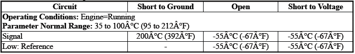
Diagnostic Fault Information
Typical Scan Tool Data
Transmission Fluid Temperature
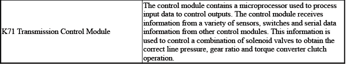
Circuit/System Description
For an overview of the component/system, refer to Transmission General Description
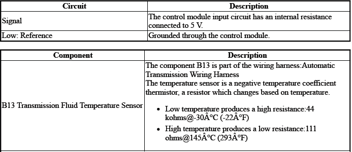
The sensor is an input to the control module K71. The input signal is used to determine the temperature of the fluid: Transmission
The control module uses this data, along with other data, to adjust or control the following:
- Driver Alert Indicator - Transmission Hot - Idle Engine
- Line Pressure
- Torque Converter Clutch
- Transmission Adaptive Values Learn
- Transmission Hot Mode
- Transmission Shifting
Conditions for Running the DTC
P0711
- DTC P0705, P0707, P0708, P0712, P0713 = Not set
- Engine Speed= Greater than 400 RPM
- Ignition Voltage=9 to 32 V
- Fail-Safe Mode=Inactive
- K71 Transmission Control Module= Communication Enabled
- Service Mode=Disabled
Frequency the DTC runs=Continuously - After the running conditions are met - For greater than 2 s
P0712
Ignition Voltage=9 to 32 V
Frequency the DTC runs=Continuously - After the running conditions are met - For greater than 2 s
P0713
- DTC P0705, P0707, P0708 = Not set
- Engine Speed= Greater than 400 RPM
- Ignition Voltage=9 to 32 V
- Transmission Range= Drive
Frequency the DTC runs=Continuously - After the running conditions are met - For greater than 2 s
Conditions for Setting the DTC
P0711Condition 1
Transmission Fluid Temperature & Engine Coolant Temperature=Not within 43ºC (77ºF) of each other
Condition 2
Transmission Fluid Temperature=The temperature does not change within 10 min & The vehicle speed has reached 40 km/h (29 MPH) at least once during this drive cycle.
Condition 3
Transmission Fluid Temperature=The temperature does not change within a predetermined time.
P0712
Transmission Fluid Temperature=Warmer than 200ºC (392ºF) - For greater than 60 s
P0713
Transmission Fluid Temperature=Colder than -55ºC (-67ºF) - For greater than 12 s
Actions Taken When the DTC Sets
DTCs listed in the DTC Descriptor Category=Type B DTC
- Autostart/Autostop=Disabled - If equipped
- Torque Converter Clutch=Disabled
- Transmission Adaptive Values Learn=Disabled
Conditions for Clearing the DTC
DTCs listed in the DTC Descriptor Category=Type B DTC
Reference Information
Schematic: Reference
Refer to Automatic Transmission Controls Wiring Schematics
Connector End View: Reference
Refer to Component Connector End View Index
Component View: Reference
Refer to Disassembled Views
Electrical Information: Reference
- Refer to Circuit Testing
- Refer to Connector Repairs
- Refer to Testing for Intermittent Conditions and Poor Connections
- Refer to Wiring Repairs
DTC Type: Reference
Refer to Powertrain Diagnostic Trouble Code (DTC) Type Definitions
Scan Tool: Reference
Refer to Control Module: References
Circuit/System Verification
1. Verify the condition does not exist: Incorrect fluid level or condition - Transmission - Refer to Transmission Fluid Level and Condition Check
- If a condition exists
Refer to Fluid Leak Diagnosis
- Go to next step: If no condition exists
2. Verify the scan tool parameter: Transmission Fluid Temperature=-39 to 199ºC (-39 to 390ºF)
- If not between -39 and 199ºC (-39 and 390ºF)
Refer to Circuit/System Testing
- Go to next step: If between -39 and 199ºC (-39 and 390ºF)
3. Operate the cold vehicle above 64 km/h (40 MPH) for 10 min.
Verify the scan tool parameter: Transmission Fluid Temperature=Temperature increases greater than 2ºC (4ºF)
- If the temperature does not increase 2ºC (4ºF) or greater
Refer to Circuit/System Testing
- Go to next step: If the temperature increases greater than 2ºC (4ºF)
4. Operate the vehicle within the Conditions for Running the DTC. You may also operate the vehicle within the conditions that you observed from the Freeze Frame/Failure Records data.
Verify the DTC does not set.
- If the DTC sets
Refer to Circuit/System Testing
- Go to next step: If the DTC is not set
5. All OK.
Circuit/System Testing
NOTE: It may take up to 2 min for all vehicle systems to power down before an accurate ground or low reference circuit continuity test can be performed.
1. Ignition/Vehicle & All vehicle systems - Off
NOTE: Twisting or tilting of the transmission control module electrical connector while disconnecting may result in bent or misaligned electrical terminal pins.
2. Remove the component: K71 Transmission Control Module.
3. Test for infinite resistance between the test points: Low: Reference circuit terminal 19 & Transmission Case.
- If less than infinite resistance
Replace the component: Automatic Transmission Wiring Harness
- Go to next step: If infinite resistance
4. Test for infinite resistance between the test points: Signal circuit terminal 10 & Transmission Case
- If less than infinite resistance
Replace the component: Automatic Transmission Wiring Harness
- Go to next step: If infinite resistance
5. Test the resistance between the test points: Low: Reference circuit terminal 19 & Signal circuit terminal 10
Verify the value is within the range listed in the table: Refer to Temperature Versus Resistance (B13 Transmission Fluid Temperature Sensor) Refer to Temperature Versus Resistance (Q27 Pressure Control Solenoid Valve) Refer to Temperature Versus Resistance (Q32 Shift Solenoid Valve 1)
- If in the specified range
Replace the component: K71 Transmission Control Module
- Go to next step: If not in the specified range
6. Test or replace the component: Automatic Transmission Wiring Harness
Repair Instructions
Perform the Diagnostic Repair Verification after completing the repair: Refer to Diagnostic Repair Verification
- Refer to Wiring Harness Wire Replacement - Automatic Transmission Wiring Harness
- For control module replacement, programming, and setup: Refer to Control Module: References
DTC P0717, P07BF, or P07C0
Diagnostic Instructions
- Perform the Diagnostic System Check prior to using this diagnostic procedure: Refer to Diagnostic System Check - Vehicle
- Review the description of Strategy Based Diagnosis: Strategy Based Diagnosis
- An overview of each diagnostic category can be found here: Refer to Diagnostic Procedure Instructions
DTC Descriptor
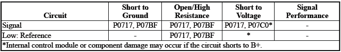
DTC P0717
Input Speed Sensor Circuit No Signal
DTC P07BF
Input Speed Sensor Circuit Low Voltage
DTC P07C0
Input Speed Sensor Circuit High Voltage
Diagnostic Fault Information
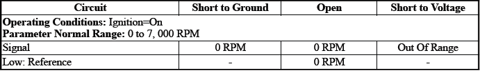
Typical Scan Tool Data
Transmission ISS
Circuit/System Description
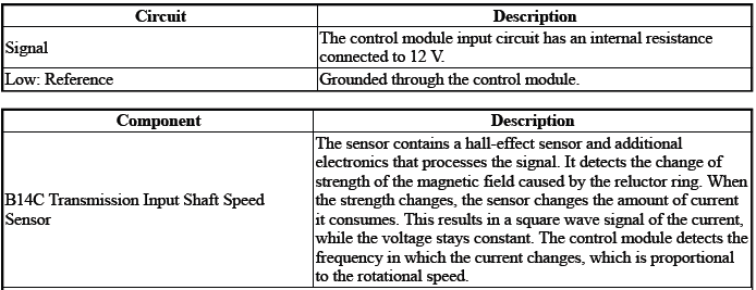
The sensor is an input to the control module K71. The input signal is used to determine the rotational speed of the component: Input Shaft
The control module uses this data, along with other data, to adjust or control the following:
- Torque Converter Clutch
- Transmission Shifting
Conditions for Running the DTC
P07BF, P07C0
- Ignition Voltage=10.2 to 15.5 V
- K71 Transmission Control Module= Communication Enabled
Frequency the DTC runs=Continuously - After the running conditions are met - For 2 s
Conditions for Setting the DTC
P0717
Transmission ISS=0 RPM & Transmission OSS=Greater than 0 RPM
P07BF
Transmission ISS=Invalid Signal Received - Short to Ground
P07C0
Transmission ISS=Invalid Signal Received - Short to Voltage
Actions Taken When the DTC Sets
DTCs listed in the DTC Descriptor Category=Type A DTC
- Autostart/Autostop=Disabled - If equipped
- Fail-Safe Mode=Active
- Learning=Disabled
- Torque Converter Clutch=Disabled
- Transmission OSS=Calculated
Conditions for Clearing the DTC
DTCs listed in the DTC Descriptor Category=Type A DTC
Reference Information
Schematic: Reference
Refer to Automatic Transmission Controls Wiring Schematics
Connector End View: Reference
Refer to Component Connector End View Index
Component View: Reference
Refer to Disassembled Views
Description and Operation
Refer to Transmission General Description
Electrical Information: Reference
- Refer to Circuit Testing
- Refer to Connector Repairs
- Refer to Testing for Intermittent Conditions and Poor Connections
- Refer to Wiring Repairs
DTC Type: Reference
Refer to Powertrain Diagnostic Trouble Code (DTC) Type Definitions
Scan Tool: Reference
Refer to Control Module: References
Circuit/System Verification
1. Engine - Running.
2. Transmission - Park.
3. Verify the scan tool parameter: Transmission ISS=Engine Speed.
- If not the specified state
Refer to Circuit/System Testing
- Go to next step: If the specified state
4. Transmission - Reverse.
5. Verify the scan tool parameter: Transmission ISS= 0.
- If not the specified state
Refer to Circuit/System Testing
- Go to next step: If the specified state
6. Operate the vehicle within the Conditions for Running the DTC. You may also operate the vehicle within the conditions that you observed from the Freeze Frame/Failure Records data.
Verify the DTC does not set.
- If the DTC sets
Refer to Circuit/System Testing
- Go to next step: If the DTC is not set
7. All OK.
Circuit/System Testing
NOTE: It may take up to 2 min for all vehicle systems to power down before an accurate ground or low reference circuit continuity test can be performed.
1. Ignition/Vehicle & All vehicle systems - Off
2. Remove the component:K71 Transmission Control Module
NOTE: Twisting or tilting of the transmission control module electrical connector while disconnecting may result in bent or misaligned electrical terminal pins.
3. Test for 4500000 to 5000000 ohms between the test points:Signal circuit terminal 18 & Low: Reference circuit terminal 17
- If not between 4500000 and 5000000 ohms
- Remove the component:Control Valve Body Cover
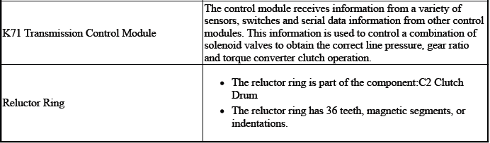
- Disconnect the electrical connector:B14C Transmission Input Shaft Speed Sensor
- Test for less than 2 ohms between the test points:
- Control circuit terminal 2@Component harness & Signal circuit terminal 18@Control module harness
- Low: Reference circuit terminal 1@Component harness & Low: Reference circuit terminal 17@Control module harness
- If 2 ohms or greater - Replace the component:Automatic Transmission Wiring Harness
- If less than 2 ohms - Replace the component:B14C Transmission Input Shaft Speed Sensor
- Go to next step: If between 4500000 and 5000000 ohms
4. Test for infinite resistance between the test points:
- Signal circuit terminal 18 & Transmission Case
- Low: Reference circuit terminal 17 & Transmission Case
- If less than infinite resistance
- Remove the component: Control Valve Body Cover
- Disconnect the electrical connector:B14C Transmission Input Shaft Speed Sensor
- Test for infinite resistance between the test points:
- Signal circuit terminal 2@Component harness & Transmission Case
- Low: Reference circuit terminal 1@Component harness & Transmission Case
- If less than infinite resistance - Replace the component: Automatic
Transmission Wiring Harness.
If less than infinite resistance - Replace the component:B14C Transmission Input Shaft Speed Sensor.
- Go to next step: If infinite resistance
5. Replace the component:K71 Transmission Control Module
Component Testing
1. Ignition/Vehicle - Off.
2. Disconnect the electrical connector:B14C Transmission Input Shaft Speed Sensor.
NOTE: The component's temperature should be 19 to 21ºC (66 to 70ºF) while testing.
3. Test for 4500000 to 5000000 ohms between the test points: Control terminal 2 & Low: Reference terminal 1.
- If not between 4500000 and 5000000 ohms
Replace the component:B14C Transmission Input Shaft Speed Sensor
- Go to next step: If between 4500000 and 5000000 ohms
4. Test for infinite resistance between the test points:Each terminal of the component & The component's housing.
- If less than infinite resistance
Replace the component:B14C Transmission Input Shaft Speed Sensor
- Go to next step: If infinite resistance
5. All OK.
Repair Instructions
Perform the Diagnostic Repair Verification after completing the repair: Refer to Diagnostic Repair Verification
- Refer to Control Valve Body Replacement
- Refer to Input Speed Sensor Replacement
- Refer to Wiring Harness Wire Replacement - Automatic Transmission Wiring Harness
- For control module replacement, programming, and setup: Refer to Control Module: References
DTC P0722, P077C, or P077D
Diagnostic Instructions
- Perform the Diagnostic System Check prior to using this diagnostic procedure: Refer to Diagnostic System Check - Vehicle
- Review the description of Strategy Based Diagnosis:Strategy Based Diagnosis
- An overview of each diagnostic category can be found here: Refer to Diagnostic Procedure Instructions
DTC Descriptor
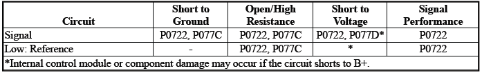
DTC P0722
Output Speed Sensor Circuit No Signal
DTC P077C
Output Speed Sensor Circuit Low Voltage
DTC P077D
Output Speed Sensor Circuit High Voltage
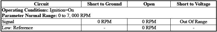
Diagnostic Fault Information
Typical Scan Tool Data
Transmission OSS
Circuit/System Description

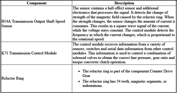
The sensor is an input to the control module K71. The input signal is used to determine the rotational speed of the component:Output Shaft The control module uses this data, along with other data, to adjust or control the following:
- Torque Converter Clutch
- Transmission Shifting
Conditions for Running the DTC
P0722
- DTC P077C, P077D, P07BF, P07C0, P0973, P0974, P0748, P0778, P0798,
P0962, P0963, P0967, P0970.
P0971, P2716, P2720, P2721, P2725, P2729, P2730, P2734, P2738, P2739 = Not set
- Engine Speed= Greater than 400 RPM
- Fail-Safe Mode=Inactive
- Ignition Voltage=10.2 to 15.5 V
- K71 Transmission Control Module= Communication Enabled
- Transmission Range=Drive
Frequency the DTC runs=Continuously - After the running conditions are met - For 2 s
P077C, P077D
- Engine Speed= Greater than 400 RPM
- Ignition Voltage=10.2 to 15.5 V
- K71 Transmission Control Module= Communication Enabled
Frequency the DTC runs=Continuously - After the running conditions are met - For 2 s
Conditions for Setting the DTC
P0722
Transmission OSS=0 RPM & Transmission ISS=Greater than 0 RPM
P077C
Transmission OSS=Invalid Signal Received - Short to Ground
P077D
Transmission OSS=Invalid Signal Received - Short to Voltage
Actions Taken When the DTC Sets
DTCs listed in the DTC Descriptor Category=Type A DTC
- Autostart/Autostop=Disabled - If equipped
- Fail-Safe Mode=Active
- { P077C, P077D }Transmission gear allowed=4th Gear - After a stop
- { P0722 }Transmission gear allowed=6th gear
- Transmission ISS=Calculated
Conditions for Clearing the DTC
DTCs listed in the DTC Descriptor Category=Type A DTC
Reference Information
Schematic: Reference
Refer to Automatic Transmission Controls Wiring Schematics
Connector End View: Reference
Refer to Component Connector End View Index
Component View: Reference
Refer to Disassembled Views
Description and Operation
Refer to Transmission General Description
Electrical Information: Reference
- Refer to Circuit Testing
- Refer to Connector Repairs
- Refer to Testing for Intermittent Conditions and Poor Connections
- Refer to Wiring Repairs
DTC Type: Reference
Refer to Powertrain Diagnostic Trouble Code (DTC) Type Definitions
Scan Tool: Reference
Refer to Control Module: References
Circuit/System Verification
1. Engine - Running.
2. Transmission - Park.
CAUTION: Support the lower control arms in the normal horizontal position in order to avoid damage to the drive axles. Do not operate the vehicle in gear with the wheels hanging down at full travel.
3. Raise and support the vehicle.
4. Transmission - Drive.
5. Verify the scan tool parameter:Transmission OSS=The value should change smoothly and gradually as the vehicle speed is increased and decreased.
- If the value does not change smoothly and gradually
Refer to Circuit/System Testing
- Go to next step: If the value does not change smoothly and gradually
6. Operate the vehicle within the Conditions for Running the DTC. You may also operate the vehicle within the conditions that you observed from the Freeze Frame/Failure Records data.
Verify the DTC does not set.
- If the DTC sets
Refer to Circuit/System Testing
- Go to next step: If the DTC is not set
7. All OK.
Circuit/System Testing
NOTE: It may take up to 2 min for all vehicle systems to power down before an accurate ground or low reference circuit continuity test can be performed.
1. Ignition/Vehicle & All vehicle systems - Off.
2. Remove the component:K71 Transmission Control Module.
NOTE: Twisting or tilting of the transmission control module electrical connector while disconnecting may result in bent or misaligned electrical terminal pins.
3. Test for 4500000 to 5000000 ohms between the test points:Signal circuit terminal 11 & Low: Reference circuit terminal 20
- If not between 4500000 and 5000000 ohms
- Remove the component:Control Valve Body Cover
- Disconnect the electrical connector:B14C Transmission Input Shaft Speed Sensor
- Test for less than 2 ohms between the test points:
- Control circuit terminal 2@Component harness & Signal circuit terminal 11@Control module harness
- Low: Reference circuit terminal 1@Component harness & Low: Reference circuit terminal 20@Control module harness
- If 2 ohms or greater - Replace the component:Automatic Transmission Wiring Harness
- If less than 2 ohms - Replace the component:B14C Transmission Input Shaft Speed Sensor
- Go to next step: If between 4500000 and 5000000 ohms
4. Test for infinite resistance between the test points:
- Signal circuit terminal 11 & Transmission Case
- Low: Reference circuit terminal 20 & Transmission Case
- If less than infinite resistance
- Remove the component:Control Valve Body Cover
- Disconnect the electrical connector:B14C Transmission Input Shaft Speed Sensor
- Test for infinite resistance between the test points:
- Signal circuit terminal 2@Component harness & Transmission Case
- Low: Reference circuit terminal 1@Component harness & Transmission Case
- If less than infinite resistance - Replace the component:Automatic Transmission Wiring Harness
- If less than infinite resistance - Replace the component:B14A Transmission Output Shaft Speed Sensor
- Go to next step: If infinite resistance
- Go to next step: If infinite resistance
5. Replace the component:K71 Transmission Control Module
Component Testing
1. Ignition/Vehicle - Off.
2. Disconnect the electrical connector:B14A Transmission Output Shaft Speed Sensor.
NOTE: The component's temperature should be 19 to 21ºC (66 to 70ºF) while testing.
3. Test for 4500000 to 5000000 ohms between the test points:Control terminal 2 & Low: Reference terminal 1.
- If not between 4500000 and 5000000 ohms
Replace the component:B14A Transmission Output Shaft Speed Sensor
- Go to next step: If between 4500000 and 5000000 ohms
4. Test for infinite resistance between the test points:Each terminal of the component & The component's housing.
- If less than infinite resistance
Replace the component:B14A Transmission Output Shaft Speed Sensor
- Go to next step: If infinite resistance
5. All OK.
Repair Instructions
Perform the Diagnostic Repair Verification after completing the repair: Refer to Diagnostic Repair Verification
- Refer to Control Valve Body Replacement
- Refer to Counter Drive Gear Removal - B14A Transmission Output Shaft Speed Sensor
- Refer to Counter Drive Gear Installation - B14A Transmission Output Shaft Speed Sensor
- Refer to Wiring Harness Wire Replacement - Automatic Transmission Wiring Harness
- For control module replacement, programming, and setup: Refer to Control Module: References
DTC P0729-P0735, P076F, or P07D9
Diagnostic Instructions
- Perform the Diagnostic System Check prior to using this diagnostic procedure: Refer to Diagnostic System Check - Vehicle
- Review the description of Strategy Based Diagnosis:Strategy Based Diagnosis
- An overview of each diagnostic category can be found here: Refer to Diagnostic Procedure Instructions
DTC Descriptor
DTC P0729
6th Gear Ratio Incorrect
DTC P0730
Gear Ratio Incorrect
DTC P0731
1st Gear Ratio Incorrect
DTC P0732
2nd Gear Ratio Incorrect
DTC P0733
3rd Gear Ratio Incorrect
DTC P0734
4th Gear Ratio Incorrect
DTC P0735
5th Gear Ratio Incorrect
DTC P076F
7th Gear Ratio Incorrect
DTC P07D9
8th Gear Ratio Incorrect
Circuit/System Description
The control module calculates gear ratio based on information from various transmission sensors and information obtained from other control modules. If the commanded gear ratio does not match the calculated gear ratio, a DTC sets.
Conditions for Running the DTC
- DTC P0711, P0712, P0713, P0742, P0717, P07BF, P07C0, P0722, P077C, P077D = Not set
- B14A Transmission Output Shaft Speed Sensor=Greater than 59 RPM
- K71 Transmission Control Module= Communication Enabled
- Ignition Voltage=9 to 32 V
- Transmission Fluid Temperature=Warmer than -20ºC (-4ºF)
- Transmission Range= Drive
- {P0729Condition 1}Transmission Gear=6th gear
- {P0729Condition 2}Transmission Gear=6th gear & Engine Torque=Greater than 59 Nm (44 lb ft)
- {P0730Condition 1}Transmission Gear=1st Gear & Engine Torque=Less than 0 Nm (0 lb ft)
- {P0730Condition 2}Transmission Gear=1st Gear & Engine Torque=Less than -20 Nm (-15 lb ft) or Greater than 29 Nm (21 lb ft)
- {P0730Condition 3}Transmission Gear=1st Gear & Engine Torque=Greater than 59 Nm (44 lb ft) & B14C
- Transmission Input Shaft Speed Sensor=Less than 6001 RPM {P0731}Transmission Gear=1st Gear & Engine Torque=Greater than 59 Nm (44 lb ft) & B14C Transmission
- Input Shaft Speed Sensor =Less than 6001 RPM
- {P0732Condition 1}Transmission Gear=2nd Gear
- {P0732Condition 2}Transmission Gear=2nd Gear & Engine Torque=Less than -20 Nm (-15 lb ft) or Greater than 29 Nm (21 lb ft)
- {P0733Condition 1}Transmission Gear=3rd Gear
- {P0733Condition 2}Transmission Gear=3rd Gear & Engine Torque=Less than -20 Nm (-15 lb ft) or Greater than 29 Nm (21 lb ft)
- {P0734Condition 1}Transmission Gear=4th Gear
- {P0734Condition 2}Transmission Gear=4th Gear & Engine Torque=Less than -20 Nm (-15 lb ft) or Greater than 29 Nm (21 lb ft)
- {P0735Condition 1}Transmission Gear=5th Gear
- {P0735Condition 2}Transmission Gear=5th Gear & Engine Torque=Less than -20 Nm (-15 lb ft) or Greater than 29 Nm (21 lb ft)
- {P076FCondition 1}Transmission Gear=7th Gear {P076FCondition 2}Transmission Gear=7th Gear & Engine Torque=Less than -20 Nm (-15 lb ft) or Greater than 29 Nm (21 lb ft)
- {P07D9Condition 1}Transmission Gear=8th Gear
- {P07D9Condition 2}Transmission Gear=8th Gear & Engine Torque=Less than -20 Nm (-15 lb ft) or Greater than 29 Nm (21 lb ft)
Frequency the DTC runs=Continuously - After the running conditions are met - For 2 s
Conditions for Setting the DTC
P0729, P0730, P0732, P0733, P0734, P0735, P076F, P07D9 - Condition 1
The following parameters are not within 20% of each other:Gear Ratio & Gear Command - For 1 s - Malfunction occurred 5 times.
P0729Condition 2
Gear Ratio=Incorrect gear ratio - Within 4% of gear 4, 5, 7, 8 ratio - For greater than 1 s - Malfunction occurred 5 times.
P0730Condition 2
Gear Ratio=Incorrect gear ratio - Within 4% of gear 3, 4 ratio - For greater than 1 s - Malfunction occurred 5 times.
P0730Condition 3
Gear Ratio=Incorrect gear ratio - Within 4% of gear 2, 5 ratio - For greater than 1 s - Malfunction occurred 5 times.
P0731
Gear Ratio=Incorrect gear ratio - Within 4% of gear 2, 4, 5 ratio - For greater than 1 s - Malfunction occurred 5 times.
P0732Condition 2
Gear Ratio=Incorrect gear ratio - Within 4% of gear 3, 4, 5, 8 ratio - For greater than 1 s - Malfunction occurred 5 times.
P0733Condition 2
Gear Ratio=Incorrect gear ratio - Within 4% of gear 2, 4, 5, 7 ratio - For greater than 1 s - Malfunction occurred 5 times.
P0734Condition 2
Gear Ratio=Incorrect gear ratio - Within 4% of gear 2, 3, 5, 6 ratio - For greater than 1 s - Malfunction occurred 5 times.
P0735Condition 2
Gear Ratio=Incorrect gear ratio - Within 4% of gear 2, 3, 4, 6, 7, 8 ratio - For greater than 1 s - Malfunction occurred 5 times.
P076FCondition 2
Gear Ratio=Incorrect gear ratio - Within 4% of gear 3, 5, 6, 8 ratio - For greater than 1 s - Malfunction occurred 5 times.
P07D9Condition 2
Gear Ratio=Incorrect gear ratio - Within 4% of gear 2, 5, 6, 7 ratio - For greater than 1 s - Malfunction occurred 5 times.
Actions Taken When the DTC Sets
DTCs listed in the DTC Descriptor Category=Type A DTC - Exceptions listed below - Additional actions taken:
DTC P0730=Type C DTC
- Autostart/Autostop=Disabled - If equipped
- Fail-Safe Mode=Enabled
- Learning=Disabled
Conditions for Clearing the DTC
DTCs listed in the DTC Descriptor Category=Type A DTC
DTC P0730=Type C DTC
Reference Information
Schematic: Reference
Refer to Automatic Transmission Controls Wiring Schematics
Connector End View: Reference
Refer to Component Connector End View Index
Component View: Reference
Refer to Disassembled Views
Description and Operation
Refer to Transmission General Description
Electrical Information: Reference
- Refer to Circuit Testing
- Refer to Connector Repairs
- Refer to Testing for Intermittent Conditions and Poor Connections
- Refer to Wiring Repairs
DTC Type: Reference
Refer to Powertrain Diagnostic Trouble Code (DTC) Type Definitions
Scan Tool: Reference
Refer to Control Module: References
Circuit/System Verification
1. Ignition - On / Vehicle - In Service Mode
2. Verify there are no DTCs set related to the following system/component:
- Q27A Pressure Control Solenoid Valve 1
- Q27B Pressure Control Solenoid Valve 2
- Q27C Pressure Control Solenoid Valve 3
- Q27D Pressure Control Solenoid Valve 4
- Q27E Pressure Control Solenoid Valve 5
- Q27F Pressure Control Solenoid Valve 6
- Q32A Shift Solenoid Valve 1
- Q32B Shift Solenoid Valve 2
- If other DTCs are set
Refer to: Diagnostic Trouble Code (DTC) List - Vehicle
- Go to next step: If no other DTCs are set
3. Verify the condition does not exist:Incorrect fluid level or condition - Transmission - Refer to Transmission Fluid Level and Condition Check
- If a condition exists
Repair or replace as necessary.
- Go to next step: If no condition exists
4. Verify the condition does not exist:Incorrect pressure - Transmission - Refer to Line Pressure Check
- If a condition exists
Replace the component:T12 Automatic Transmission Assembly
- Go to next step: If no condition exists
5. Clear the DTCs.
6. Perform the configuration/reset function: Refer to Learned Values Reset
7. Road test the vehicle. - Refer to Road Test.
8. Verify DTC P0729, P0730, P0731, P0732, P0733, P0734, P0735, P076F, P07D9 is not set.
- {Test failed 1 time (s) }If any of the DTCs are set
- Replace the component: K71 Transmission Control Module
- Refer to:Step 5
- {Test failed 2 time (s) }If any of the DTCs are set
- Replace the component: Control Valve Body
- Refer to:Step 5
- {Test failed 3 time (s) }If any of the DTCs are set
- Replace the component: T12 Automatic Transmission Assembly
- Refer to:Step 5
- Go to next step: If none of the DTCs are set
9. Operate the vehicle within the Conditions for Running the DTC. You may also operate the vehicle within the conditions that you observed from the Freeze Frame/Failure Records data.
Verify the DTC does not set.
- If the DTC sets
Refer to:Step 1
- Go to next step: If the DTC is not set
10. All OK.
Repair Instructions
Perform the Diagnostic Repair Verification after completing the repair: Refer to Diagnostic Repair Verification
- Refer to Control Valve Body Replacement
- Refer to Transmission Replacement
- For control module replacement, programming, and setup: Refer to Control Module: References
DTC P0741 or P0742
Diagnostic Instructions
- Perform the Diagnostic System Check prior to using this diagnostic procedure: Refer to Diagnostic System Check - Vehicle
- Review the description of Strategy Based Diagnosis:Strategy Based Diagnosis
- An overview of each diagnostic category can be found here: Refer to Diagnostic Procedure Instructions
DTC Descriptor
DTC P0741
Torque Converter Clutch (TCC) Pressure Control Solenoid Valve Stuck Off
DTC P0742
Torque Converter Clutch (TCC) System Stuck On
Circuit/System Description
The following inputs are used to determine TCC slip speed:
- Crankshaft Position Sensor
- Transmission ISS
When the amount of TCC slip is greater than desired, DTC P0741 sets.When the amount of TCC slip is less than desired, DTC P0742 sets.
Conditions for Running the DTC
- DTC P0711, P0712, P0713 P0717, P07BF, P07C0, P0722, P077C, P077D, P2761, P2763, P2764 = Not set
- { P0742 }Engine Speed=1000 to 3000 RPM & Engine Torque=Greater than 60 Nm (44 lb ft)
- { P0741 }Engine Speed=Less than 4001 RPM & Engine Torque=Greater than 0 Nm (0 lb ft)
- Ignition=9 to 32 V
- Transmission Range=Drive
- Transmission Fluid Temperature=Greater than 19ºC (66ºF)
Frequency the DTC runs=Continuously - After the running conditions are met - For 2 s
Conditions for Setting the DTC
P0741
Torque Converter Clutch=Applied & TCC Slip Speed=Greater than 100 RPM - For greater than 18 s
P0742
Torque Converter Clutch=Released & TCC Slip Speed=Less than 30 RPM - For greater than 24 s
Actions Taken When the DTC Sets
DTC P0741=Type B DTC
DTC P0742=Type C DTC
- { P0742 }Autostart/Autostop=Disabled - If equipped
- Learning=Disabled
- Torque Converter Clutch=Disabled
Conditions for Clearing the DTC
DTC P0741=Type B DTC
DTC P0742=Type C DTC
Reference Information
Schematic: Reference
Refer to Automatic Transmission Controls Wiring Schematics.
Connector End View: Reference
Refer to Component Connector End View Index.
Component View: Reference
Refer to Disassembled Views.
Description and Operation
Refer to Transmission General Description.
Electrical Information: Reference
- Refer to Circuit Testing
- Refer to Connector Repairs
- Refer to Testing for Intermittent Conditions and Poor Connections
- Refer to Wiring Repairs
DTC Type: Reference
Refer to Powertrain Diagnostic Trouble Code (DTC) Type Definitions.
Scan Tool: Reference
Refer to Control Module: References.
Circuit/System Verification
1. Ignition - On / Vehicle - In Service Mode
2. Verify there are no DTCs set related to the following system/component:Q39A Torque Converter Clutch Pressure Control Solenoid Valve
- If other DTCs are set
Refer to: Diagnostic Trouble Code (DTC) List - Vehicle
- Go to next step: If no other DTCs are set
3. Verify the condition does not exist:Incorrect fluid level or condition - Transmission - Refer to Transmission Fluid Level and Condition Check
- If a condition exists
Repair or replace as necessary.
- Go to next step: If no condition exists
4. Clear the DTCs.
5. Perform the configuration/reset function: Refer to Learned Values Reset.
6. Road test the vehicle. - Refer to Road Test.
7. Verify DTC P0741, P0742 is not set.
- {Test failed 1 time (s) }If any of the DTCs are set
- Replace the component:K71 Transmission Control Module
- Refer to:Step 5
- {Test failed 2 time (s) }If any of the DTCs are set
- Replace the component: Control Valve Body
- Refer to:Step 5
- {Test failed 3 time (s) }If any of the DTCs are set
- Replace the component: T12 Automatic Transmission Assembly
- Refer to:Step 5
- Go to next step: If none of the DTCs are set
8. Operate the vehicle within the Conditions for Running the DTC. You may also operate the vehicle within the conditions that you observed from the Freeze Frame/Failure Records data.
Verify the DTC does not set.
- If the DTC sets
Refer to:Step 1
- Go to next step: If the DTC is not set
9. All OK.
Repair Instructions
Perform the Diagnostic Repair Verification after completing the repair: Refer to Diagnostic Repair Verification
- Refer to Control Valve Body Replacement
- Refer to Torque Converter Replacement
- Refer to Transmission Replacement
- For control module replacement, programming, and setup: Refer to Control Module: References
DTC P0748, P0962, or P0963
Diagnostic Instructions
- Perform the Diagnostic System Check prior to using this diagnostic procedure: Refer to Diagnostic System Check - Vehicle
- Review the description of Strategy Based Diagnosis: Refer to Strategy Based Diagnosis
- An overview of each diagnostic category can be found here: Refer to Diagnostic Procedure Instructions
DTC Descriptor
DTC P0748
Pressure Control Solenoid Valve 1 Control Circuit
DTC P0962
Pressure Control Solenoid Valve 1 Control Circuit Low Voltage
DTC P0963
Pressure Control Solenoid Valve 1 Control Circuit High Voltage
Diagnostic Fault Information

Typical Scan Tool Data
Pressure Control Solenoid Valve 1 Control Circuit High Voltage Test Status
Pressure Control Solenoid Valve 1 Control Circuit Low Voltage Test Status
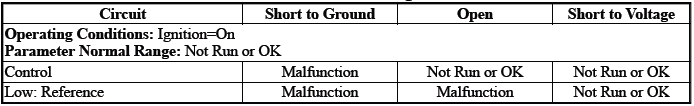
Pressure Control Solenoid Valve 1 Control Circuit Open Test Status
Circuit/System Description
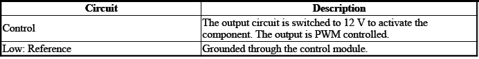
The solenoid valve controls the flow of transmission fluid to the hydraulic actuator that controls the C1 clutch.
Conditions for Running the DTC
- { P0748 }DTC P0606, P0657, P0962, P0963, P0966, P0967, P0970, P0971, P2720, P2721, P2729, P2730, P2738, P2739 = Not set
- { P0962 }DTC P0606, P0657, P0963, P0967, P0971, P2721, P2730, P2739 = Not set
- { P0963 }DTC P0606, P0657, P0962, P0966, P0970, P2720, P2729, P2738, = Not set
- Ignition Voltage=9 to 32 V
Frequency the DTC runs=Continuously - After the running conditions are met
Conditions for Setting the DTC
P0748
Control Circuit=Commanded state does not match the actual state
P0962
Control Circuit=Less than 20 mA - For greater than 1 s
P0963
Control Circuit=Greater than 1358 mA - For greater than 1 s
Actions Taken When the DTC Sets
DTCs listed in the DTC Descriptor Category=Type A DTC
- Fail-Safe Mode=Active
- Learning=Disabled
- Transmission gear allowed=3rd Gear - After a stop
Conditions for Clearing the DTC
DTCs listed in the DTC Descriptor Category=Type A DTC
Reference Information
Schematic: Reference
Refer to Automatic Transmission Controls Wiring Schematics.
Connector End View: Reference
Refer to Component Connector End View Index.
Component View: Reference
Refer to Disassembled Views.
Description and Operation
Refer to Transmission General Description.
Electrical Information: Reference
- Refer to Circuit Testing
- Refer to Connector Repairs
- Refer to Testing for Intermittent Conditions and Poor Connections
- Refer to Wiring Repairs
DTC Type: Reference
Refer to Powertrain Diagnostic Trouble Code (DTC) Type Definitions.
Scan Tool: Reference
Refer to Control Module: References.
Circuit/System Verification
1. Ignition - On / Vehicle - In Service Mode
2. Perform the scan tool control function:Pressure Control Solenoid Valve 1 - Increase & Decrease
Verify the scan tool parameter:
- Pressure Control Solenoid Valve 1 High Voltage Test Status=Not Run or OK
- Pressure Control Solenoid Valve 1 Control Circuit Low Voltage Test Status=Not Run or OK
- Pressure Control Solenoid Valve 1 Control Circuit Open Test Status=Not Run or OK
- If not the specified state
Refer to Circuit/System Testing
- Go to next step: If the specified state
3. Perform the scan tool control function:Pressure Control Solenoid Valve 1 - Enable & Disable
Verify the component produces a clicking sound:Q27A Pressure Control Solenoid Valve 1
- If the component does not produce a sound
Refer to Circuit/System Testing
- Go to next step: If the component produces a sound
4. Operate the vehicle within the Conditions for Running the DTC. You may also operate the vehicle within the conditions that you observed from the Freeze Frame/Failure Records data.
Verify the DTC does not set.
- If the DTC sets
Refer to Circuit/System Testing
- Go to next step: If the DTC is not set
5. All OK.
Circuit/System Testing
NOTE: It may take up to 2 min for all vehicle systems to power down before an accurate ground or low reference circuit continuity test can be performed.
1. Ignition/Vehicle & All vehicle systems - Off
NOTE: Twisting or tilting of the transmission control module electrical connector while disconnecting may result in bent or misaligned electrical terminal pins.
2. Remove the component:K71 Transmission Control Module
NOTE: The component's temperature should be 19 to 21ºC (66 to 70ºF) while testing.
3. Test for 5.0 to 5.6 ohms between the test points:Control circuit terminal 13 & Low: Reference circuit terminal 14
- If not between 5.0 and 5.6 ohms
- Remove the component:Control Valve Body Cover
- Disconnect the electrical connector:Q27A Pressure Control Solenoid Valve 1
- Test for less than 2 ohms between the test points:
- Control circuit terminal 2@Component harness & Control circuit terminal 13@Control module harness
- Low: Reference circuit terminal 1@Component harness & Low: Reference circuit terminal 14@Control module harness
- If 2 ohms or greater - Replace the component:Automatic Transmission Wiring Harness
- If less than 2 ohms - Replace the component:Q27A Pressure Control Solenoid Valve 1
- Go to next step: If between 5.0 and 5.6 ohms
4. Test for infinite resistance between the test points:
- Control circuit terminal 13 & Transmission Case
- Low: Reference circuit terminal 14 & Transmission Case
- If less than infinite resistance
- Remove the component:Control Valve Body Cover
- Disconnect the electrical connector:Q27A Pressure Control Solenoid Valve 1
- Test for infinite resistance between the test points:
- Control circuit terminal 2@Component harness & Transmission Case
- Low: Reference circuit terminal 1@Component harness & Transmission Case
- If less than infinite resistance - Replace the component:Automatic Transmission Wiring Harness
- If infinite resistance - Replace the component:Control Valve Body
- Go to next step: If infinite resistance
5. Replace the component:K71 Transmission Control Module
Component Testing
1. Ignition/Vehicle - Off.
2. Disconnect the electrical connector:Q27A Pressure Control Solenoid Valve 1.
NOTE: The component's temperature should be 19 to 21ºC (66 to 70ºF) while testing.
3. Test for 5.0 to 5.6 ohms between the test points:Control terminal 2 & Low: Reference terminal 1
- If not between 5.0 and 5.6 ohms
Replace the component:Control Valve Body
- Go to next step: If between 5.0 and 5.6 ohms
4. Test for infinite resistance between the test points:Each terminal of the component & The component's housing
- If less than infinite resistance
Replace the component:Control Valve Body
- Go to next step: If infinite resistance
5. All OK.
Repair Instructions
Perform the Diagnostic Repair Verification after completing the repair: Refer to Diagnostic Repair Verification
- Refer to Control Valve Body Replacement
- Refer to Wiring Harness Wire Replacement
- For control module replacement, programming, and setup: Refer to Control Module: References
DTC P0776, P07A2, or P2719
Diagnostic Instructions
- Perform the Diagnostic System Check prior to using this diagnostic procedure: Refer to Diagnostic System Check - Vehicle
- Review the description of Strategy Based Diagnosis:Strategy Based Diagnosis
- An overview of each diagnostic category can be found here: Refer to Diagnostic Procedure Instructions
DTC Descriptor
DTC P0776
Transmission Control Solenoid Valve 2 Stuck Off
DTC P07A2
Transmission Clutch 1 Performance
DTC P2719
Transmission Control Solenoid Valve 4 Performance
Circuit/System Description
When in Drive, the solenoid valve controls pressure to the C1 clutch regulator valve, or when in Reverse, the solenoid valve controls pressure to the C3 clutch regulator valve. These DTC's indicate a hydraulic /mechanical problem with the valve body or fluid pressure which is controlled by solenoid valves and is part of the control solenoid valve assembly which has no serviceable parts. With a loss of pressurized fluid, an incorrect gear ratio may result causing a Neutral condition or NO drive in all gears.
Conditions for Running the DTC
P0776, P07A2, P2719
- DTC P0563, P0601, P0602, P0604, P0711, P0712, P0713, P0717, P07BF, P07C0, P0722, P0741, P0742, P0748, P077C, P077D, P0798, P0962, P0963, P0970, P0971 = Not set
- Battery Voltage=9 to 32 V
- { P0776 }Current Gear=1, 2, 3, 4, 5
- { P07A2 }Current Gear=1, 2, 3, 4, 6
- { P2719 }Current Gear=Reverse & Shift Solenoid Valve 1 Command=Off
- Engine Speed=Greater than 600 RPM
- Garage Shift =No
- Ignition=On
- Transmission Fluid Temperature=Warmer than -10ºC (14ºF)
- Transmission ISS=Less than 200 RPM
- Transmission OSS=Less than 501 RPM
- Transmission Torque Command=Off
Frequency the DTC runs=Continuously - After the running conditions are met
Conditions for Setting the DTC
Condition 1
- Transmission Fluid Temperature=Warmer than 0ºC (32ºF)
- The difference between the following parameters is less than 150 RPM:Engine Speed & Transmission Input Speed - For greater than 3 s
Condition 2
- Transmission Fluid Temperature=-10 to -1ºC (14 to 30ºF)
- The difference between the following parameters is less than 300 RPM:Engine Speed & Transmission Input Speed - For greater than 10 s
Actions Taken When the DTC Sets
DTCs listed in the DTC Descriptor Category=Type C DTC - Exceptions listed below - Additional actions taken:
- Engagement of Reverse Gear=Shift Solenoid Valve 1 Command - ON
- Learning=Disabled
DTC P0776=DTC A - Additional actions taken:
- Torque Converter Clutch Solenoid Control=Disabled
- Manual Shift Control=Disabled
Conditions for Clearing the DTC
- DTCs listed in the DTC Descriptor Category=Type C DTC
- DTC P0776=DTC A
Reference Information
Schematic: Reference
Refer to Automatic Transmission Controls Wiring Schematics.
Connector End View: Reference
- Refer to Component Connector End View Index
- Refer to Inline Harness Connector End View Index
Component View: Reference
Refer to Disassembled Views.
Description and Operation
- Refer to Electronic Component Description
- Refer to Transmission General Description
Electrical Information: Reference
- Refer to Circuit Testing
- Refer to Connector Repairs
- Refer to Testing for Intermittent Conditions and Poor Connections
- Refer to Wiring Repairs
DTC Type: Reference
Refer to Powertrain Diagnostic Trouble Code (DTC) Type Definitions.
Scan Tool: Reference
Refer to Control Module: References.
Circuit/System Verification
1. Ignition - On / Vehicle - In Service Mode.
2. Verify there are no DTCs set related to the following system/component:
- Q27A Pressure Control Solenoid Valve 1
- Q27B Pressure Control Solenoid Valve 2
- Q27D Pressure Control Solenoid Valve 4
- If other DTCs are set
Refer to: Diagnostic Trouble Code (DTC) List - Vehicle
- Go to next step: If no other DTCs are set
3. Verify the condition does not exist:Incorrect fluid level or condition - Transmission - Refer to Transmission Fluid Level and Condition Check.
- If a condition exists
Repair or replace as necessary.
- Go to next step: If no condition exists
4. Verify there are no DTCs set related to the following system/component:K173 Transmission Range Control Module - If equipped
- If any DTC is set
Refer to: Diagnostic Trouble Code (DTC) List - Vehicle
- Go to next step: If no DTC is set
5. Clear the DTCs.
6. Perform the configuration/reset function: Refer to Learned Values Reset.
7. Road test the vehicle. - Refer to Road Test.
8. Verify DTC P0776, P07A2, P2719 is not set.
- {Test failed 1 time (s) }If any of the DTCs are set
- Replace the component: Control Valve Body
- Refer to:Step 5
- {Test failed 2 time (s) }If any of the DTCs are set
- Replace the component: K71 Transmission Control Module
- Refer to:Step 5
- {Test failed 3 time (s) }If any of the DTCs are set
- Replace the component: T12 Automatic Transmission Assembly
- Refer to:Step 5
- Go to next step: If none of the DTCs are set
9. Operate the vehicle within the Conditions for Running the DTC. You may also operate the vehicle within the conditions that you observed from the Freeze Frame/Failure Records data.
Verify the DTC does not set.
- If the DTC sets
Refer to:Step 1
- Go to next step: If the DTC is not set
10. All OK.
Repair Instructions
Perform the Diagnostic Repair Verification after completing the repair: Refer to Diagnostic Repair Verification
- Refer to Control Valve Body Replacement
- Refer to Transmission Replacement
- For control module replacement, programming, and setup: Refer to Control Module: References
DTC P0778, P0966, or P0967
Diagnostic Instructions
- Perform the Diagnostic System Check prior to using this diagnostic procedure: Refer to Diagnostic System Check - Vehicle
- Review the description of Strategy Based Diagnosis: Refer to Strategy Based Diagnosis
- An overview of each diagnostic category can be found here: Refer to Diagnostic Procedure Instructions
DTC Descriptor
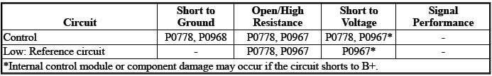
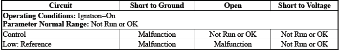
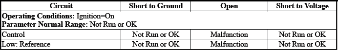
DTC P0778
Pressure Control Solenoid Valve 2 Control Circuit
DTC P0966
Pressure Control Solenoid Valve 2 Control Circuit Low Voltage
DTC P0967
Pressure Control Solenoid Valve 2 Control Circuit High Voltage
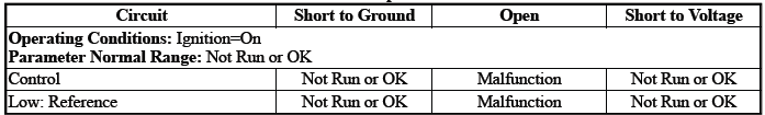
Diagnostic Fault Information
Typical Scan Tool Data
Pressure Control Solenoid Valve 2 Control Circuit High Voltage Test Status

Pressure Control Solenoid Valve 2 Control Circuit Low Voltage Test Status
Pressure Control Solenoid Valve 2 Control Circuit Open Test Status
Circuit/System Description
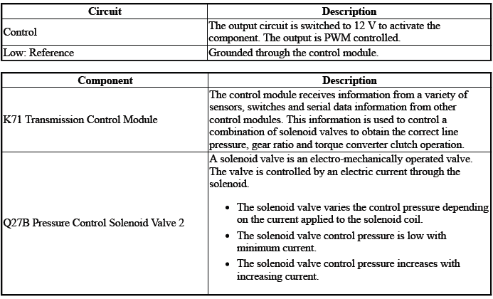
The solenoid valve controls the flow of transmission fluid to the hydraulic actuator that controls the C2 clutch.
Conditions for Running the DTC
- { P0778 }DTC P0606, P0657, P0962, P0963, P0966, P0967, P0970, P0971, P2720, P2721, P2729, P2730, P2738, P2739 = Not set
- { P0966 }DTC P0606, P0657, P0963, P0967, P0971, P2721, P2730, P2739 = Not set
- { P0967 }DTC P0606, P0657, P0962, P0966, P0970, P2720, P2729, P2738, = Not set
- Ignition Voltage=9 to 32 V
Frequency the DTC runs=Continuously - After the running conditions are met
Conditions for Setting the DTC
P0778
Control Circuit=Commanded state does not match the actual state
P0966
Control Circuit=Less than 20 mA - For greater than 1 s
P0967
Control Circuit=Greater than 1358 mA - For greater than 1 s
Actions Taken When the DTC Sets
DTCs listed in the DTC Descriptor Category=Type A DTC
- Fail-Safe Mode=Active
- Learning=Disabled
- Transmission gear allowed=3rd Gear - After a stop
Conditions for Clearing the DTC
DTCs listed in the DTC Descriptor Category=Type A DTC
Reference Information
Schematic: Reference
Refer to Automatic Transmission Controls Wiring Schematics.
Connector End View: Reference
Refer to Component Connector End View Index.
Component View: Reference
Refer to Disassembled Views.
Description and Operation
Refer to Transmission General Description.
Electrical Information: Reference
- Refer to Circuit Testing
- Refer to Connector Repairs
- Refer to Testing for Intermittent Conditions and Poor Connections
- Refer to Wiring Repairs
DTC Type: Reference
Refer to Powertrain Diagnostic Trouble Code (DTC) Type Definitions.
Scan Tool: Reference
Refer to Control Module: References.
Circuit/System Verification
1. Ignition - On / Vehicle - In Service Mode
2. Perform the scan tool control function:Pressure Control Solenoid Valve 2 - Enable & Disable
Verify the scan tool parameter:
- Pressure Control Solenoid Valve 2 Control Circuit High Voltage Test Status=Not Run or OK
- Pressure Control Solenoid Valve 2 Control Circuit Low Voltage Test Status=Not Run or OK
- Pressure Control Solenoid Valve 2 Open Circuit Test Status=Not Run or OK
- If not the specified state
Refer to Circuit/System Testing
- Go to next step: If the specified state
3. Perform the scan tool control function:Pressure Control Solenoid Valve 2 - Increase & Decrease
Verify the component produces a clicking sound:Q27B Pressure Control Solenoid Valve 2
- If the component does not produce a sound
Refer to Circuit/System Testing
- Go to next step: If the component produces a sound
4. Operate the vehicle within the Conditions for Running the DTC. You may also operate the vehicle within the conditions that you observed from the Freeze Frame/Failure Records data.
Verify the DTC does not set.
- If the DTC sets
Refer to Circuit/System Testing
- Go to next step: If the DTC is not set
5. All OK.
Circuit/System Testing
NOTE: It may take up to 2 min for all vehicle systems to power down before an accurate ground or low reference circuit continuity test can be performed.
1. Ignition/Vehicle & All vehicle systems - Off
NOTE: Twisting or tilting of the transmission control module electrical connector while disconnecting may result in bent or misaligned electrical terminal pins.
2. Remove the component:K71 Transmission Control Module
NOTE: The component's temperature should be 19 to 21ºC (66 to 70ºF) while testing.
3. Test for 5.0 to 5.6 ohms between the test points:Control circuit terminal 8 & Low: Reference circuit terminal 9
- If not between 5.0 and 5.6 ohms
- Remove the component:Control Valve Body Cover
- Disconnect the electrical connector:Q27B Pressure Control Solenoid Valve 2
- Test for less than 2 ohms between the test points:
- Control circuit terminal 2@Component harness & Control circuit terminal 8@Control module harness
- Low: Reference circuit terminal 1@Component harness & Low: Reference circuit terminal 9@Control module harness
- If 2 ohms or greater - Replace the component:Automatic Transmission Wiring Harness
- If less than 2 ohms - Replace the component:Q27B Pressure Control Solenoid Valve 2
- Go to next step: If between 5.0 and 5.6 ohms
4. Test for infinite resistance between the test points:
- Control circuit terminal 8 & Transmission Case
- Low: Reference circuit terminal 9 & Transmission Case
- If less than infinite resistance
- Remove the component:Control Valve Body Cover
- Disconnect the electrical connector:Q27B Pressure Control Solenoid Valve 2
- Test for infinite resistance between the test points:
- Control circuit terminal 2@Component harness & Transmission Case
- Low: Reference circuit terminal 1@Component harness & Transmission Case
- If less than infinite resistance - Replace the component:Automatic Transmission Wiring Harness
- If infinite resistance - Replace the component:Control Valve Body
- Go to next step: If infinite resistance
5. Replace the component:K71 Transmission Control Module
Component Testing
1. Ignition/Vehicle - Off
2. Disconnect the electrical connector:Q27B Pressure Control Solenoid Valve 2
NOTE: The component's temperature should be 19 to 21ºC (66 to 70ºF) while testing.
3. Test for 5.0 to 5.6 ohms between the test points:Control terminal 2 & Low: Reference terminal 1
- If not between 5.0 and 5.6 ohms
Replace the component:Control Valve Body
- Go to next step: If between 5.0 and 5.6 ohms
4. Test for infinite resistance between the test points:Each terminal of the component & The component's housing
- If less than infinite resistance
Replace the component:Control Valve Body
- Go to next step: If infinite resistance
5. All OK.
Repair Instructions
Perform the Diagnostic Repair Verification after completing the repair: Refer to Diagnostic Repair Verification
- Refer to Control Valve Body Replacement
- Refer to Wiring Harness Wire Replacement
- For control module replacement, programming, and setup: Refer to Control Module: References
DTC P0798, P0970, or P0971
Diagnostic Instructions
- Perform the Diagnostic System Check prior to using this diagnostic procedure: Refer to Diagnostic System Check - Vehicle
- Review the description of Strategy Based Diagnosis: Refer to Strategy Based Diagnosis
- An overview of each diagnostic category can be found here: Refer to Diagnostic Procedure Instructions
DTC Descriptor
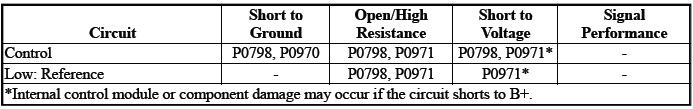
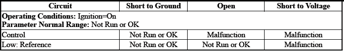
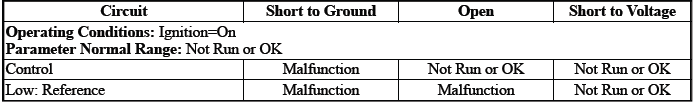
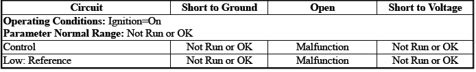
DTC P0798
Pressure Control Solenoid Valve 3 Control Circuit
DTC P0970
Pressure Control Solenoid Valve 3 Control Circuit Low Voltage
DTC P0971
Pressure Control Solenoid Valve 3 Control Circuit High Voltage
Diagnostic Fault Information
Typical Scan Tool Data
Pressure Control Solenoid Valve 3 Control Circuit High Voltage Test Status
Pressure Control Solenoid Valve 3 Control Circuit Low Voltage Test Status
Pressure Control Solenoid Valve 3 Control Circuit Open Test Status
Circuit/System Description
For an overview of the component/system, refer to Transmission General Description
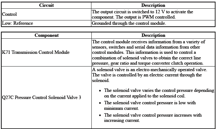
The solenoid valve controls the flow of transmission fluid to the hydraulic actuator that controls the C3 clutch.
Conditions for Running the DTC
- { P0798 }DTC P0606, P0657, P0962, P0963, P0966, P0967, P0970, P0971, P2720, P2721, P2729, P2730, P2738, P2739 = Not set
- { P0970 }DTC P0606, P0657, P0963, P0967, P0971, P2721, P2730, P2739 = Not set
- { P0971 }DTC P0606, P0657, P0962, P0966, P0970, P2720, P2729, P2738, = Not set
- Ignition Voltage=9 to 32 V
Frequency the DTC runs=Continuously - After the running conditions are met - For greater than 2 s
Conditions for Setting the DTC
P0798
Control Circuit=Commanded state does not match the actual state - For greater than 1 s
P0970
Control Circuit=Less than 20 mA - For greater than 1 s
P0971
Control Circuit=Greater than 1, 358 mA - For greater than 1 s
Actions Taken When the DTC Sets
DTCs listed in the DTC Descriptor Category=Type A DTC
- Learning=Disabled
- Fail-Safe Mode=Active
- Transmission gear allowed=3rd Gear - After a stop
Conditions for Clearing the DTC
DTCs listed in the DTC Descriptor Category=Type A DTC
Reference Information
Schematic: Reference
Refer to Automatic Transmission Controls Wiring Schematics.
Connector End View: Reference
Refer to Component Connector End View Index.
Component View: Reference
Refer to Disassembled Views.
Description and Operation
Electrical Information: Reference
- Refer to Circuit Testing
- Refer to Connector Repairs
- Refer to Testing for Intermittent Conditions and Poor Connections
- Refer to Wiring Repairs
DTC Type: Reference
Refer to Powertrain Diagnostic Trouble Code (DTC) Type Definitions.
Scan Tool: Reference
Refer to Control Module: References.
Circuit/System Verification
1. Ignition - On / Vehicle - In Service Mode
2. Perform the scan tool control function:Pressure Control Solenoid Valve 3 - Increase & Decrease
Verify the scan tool parameter:
- Pressure Control Solenoid Valve 3 Control Circuit High Voltage Test Status=Not Run or OK
- Pressure Control Solenoid Valve 3 Control Circuit Low Voltage Test Status=Not Run or OK
- Pressure Control Solenoid Valve 3 Control Circuit Open Test Status=Not Run or OK
- If not the specified state
Refer to Circuit/System Testing
- Go to next step: If the specified state
3. Perform the scan tool control function:Pressure Control Solenoid Valve 3 - Enable & Disable Verify the component produces a clicking sound:Q27C Pressure Control Solenoid Valve 3
- If the component does not produce a sound
Refer to Circuit/System Testing
- Go to next step: If the component produces a sound
4. Operate the vehicle within the Conditions for Running the DTC. You may also operate the vehicle within the conditions that you observed from the Freeze Frame/Failure Records data.
Verify the DTC does not set.
- If the DTC sets
Refer to Circuit/System Testing
- Go to next step: If the DTC is not set
5. All OK.
Circuit/System Testing
NOTE: It may take up to 2 min for all vehicle systems to power down before an accurate ground or low reference circuit continuity test can be performed.
1. Ignition/Vehicle & All vehicle systems - Off
NOTE: Twisting or tilting of the transmission control module electrical connector while disconnecting may result in bent or misaligned electrical terminal pins.
2. Remove the component:K71 Transmission Control Module
3. Test for 5.0 to 5.6 ohms between the test points:Control circuit terminal 3 & Low: Reference circuit terminal 4
- If not between 5.0 and 5.6 ohms
- Remove the component:Control Valve Body Cover
- Disconnect the electrical connector:Q27C Pressure Control Solenoid Valve 3
- Test for less than 2 ohms between the test points:
- Control circuit terminal 2@Component harness & Control circuit terminal 3@Control module harness
- Low: Reference circuit terminal 1@Component harness & Low: Reference circuit terminal 4@Control module harness
- If 2 ohms or greater - Replace the component:Automatic Transmission Wiring Harness
- If less than 2 ohms - Replace the component:Q27C Pressure Control Solenoid Valve 3
- Go to next step: If between 5.0 and 5.6 ohms
4. Test for infinite resistance between the test points:
- Control circuit terminal 3 & Transmission Case
- Low: Reference circuit terminal 4 & Transmission Case
- If less than infinite resistance
- Remove the component:Control Valve Body Cover
- Disconnect the electrical connector:Q27C Pressure Control Solenoid Valve 3
- Test for infinite resistance between the test points:
- Control circuit terminal 2@Component harness & Transmission Case
- Low: Reference circuit terminal 1@Component harness & Transmission Case
- If less than infinite resistance - Replace the component:Automatic Transmission Wiring Harness
- If infinite resistance - Replace the component:Control Valve Body
- Go to next step: If infinite resistance
5. Replace the component:K71 Transmission Control Modul
Component Testing
1. Ignition/Vehicle - Off
2. Disconnect the electrical connector:Q27C Pressure Control Solenoid Valve 3
NOTE: The component's temperature should be 19 to 21ºC (66 to 70ºF) while testing.
3. Test for 5.0 to 5.6 ohms between the test points:Control terminal 2 & Low: Reference terminal 1
- If not between 5.0 and 5.6 ohms
Replace the component:Control Valve Body
- Go to next step: If between 5.0 and 5.6 ohms
4. Test for infinite resistance between the test points:Each terminal of the component & The component's housing
- If less than infinite resistance
Replace the component:Control Valve Body
- Go to next step: If infinite resistance
5. All OK.
Repair Instructions
Perform the Diagnostic Repair Verification after completing the repair: Refer to Diagnostic Repair Verification
- Refer to Control Valve Body Replacement
- Refer to Wiring Harness Wire Replacement
- For control module replacement, programming, and setup: Refer to Control Module: References
DTC P0815, P0816, or P0826
Diagnostic Instructions
- Perform the Diagnostic System Check prior to using this diagnostic procedure: Refer to Diagnostic System Check - Vehicle
- Review the description of Strategy Based Diagnosis: Refer to Strategy Based Diagnosis
- An overview of each diagnostic category can be found here: Refer to Diagnostic Procedure Instructions
DTC Descriptor
DTC P0815
Upshift Switch Circuit
DTC P0816
Downshift Switch Circuit
DTC P0826
Up and Down Shift Switch Circuit
Diagnostic Fault Information
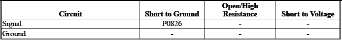
Typical Scan Tool Data
Driver Shift Request
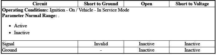
Circuit/System Description
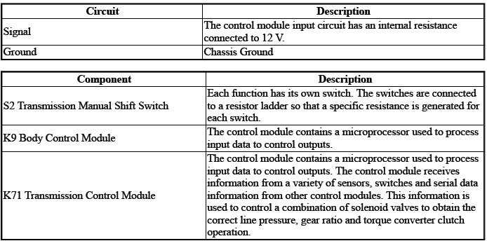
The switch S2 has an internal resistor ladder network. A specific resistance is generated dependent on the position of the switch.
Conditions for Running the DTC
- Ignition Voltage=9 to 32 V
- K71 Transmission Control Module= Communication Enabled
- K9 Body Control Module= Communication Enabled
Frequency the DTC runs=Continuously - After the running conditions are met - For 2 s
Conditions for Setting the DTC
P0815Condition 1
- Transmission Range=Park/Neutral/Reverse
- Driver Shift Request=Upshift
The above conditions must occur for greater than 2 s.
Condition 2
- Transmission Range=Drive
- Driver Shift Request=Upshift
The above conditions must occur for greater than 29 s.
P0816Condition 1
- Transmission Range=Park/Neutral/Reverse
- Driver Shift Request=Downshift
The above conditions must occur for greater than 2 s.
Condition 2
- Transmission Range=Drive
- Driver Shift Request=Downshift
The above conditions must occur for greater than 29 s.
P0826
Driver Shift Request=Illegal Mode
Actions Taken When the DTC Sets
DTCs P0815, P0816, P0826 are Type C DTCs.
Manual Shift Control=Disabled
Conditions for Clearing the DTC
DTCs P0815, P0816, P0826 are Type C DTCs.
Reference Information
Schematic: Reference
Refer to Automatic Transmission Controls Wiring Schematics.
Connector End View: Reference
Refer to Component Connector End View Index.
Component View: Reference
Refer to Disassembled Views.
Description and Operation
Refer to Transmission General Description.
Electrical Information: Reference
- Refer to Circuit Testing
- Refer to Connector Repairs
- Refer to Testing for Intermittent Conditions and Poor Connections
- Refer to Wiring Repairs
DTC Type: Reference
Refer to Powertrain Diagnostic Trouble Code (DTC) Type Definitions.
Scan Tool: Reference
Refer to Control Module: References.
Circuit/System Verification
NOTE: It may take up to 2 min for all vehicle systems to power down before an accurate ground or low reference circuit continuity test can be performed.
1. Ignition - On / Vehicle - In Service Mode
2. Verify the scan tool parameter:Driver Shift Request=Inactive
- If not the specified state
Refer to Circuit/System Testing
- Go to next step: If the specified state
3. Operate the component:S2 Transmission Manual Shift Switch
Verify the scan tool parameter:Driver Shift Request=Upshift/Downshift
- If not the specified state
Refer to Circuit/System Testing
- Go to next step: If the specified state
4. Operate the vehicle within the Conditions for Running the DTC. You may also operate the vehicle within the conditions that you observed from the Freeze Frame/Failure Records data.
Verify the DTC does not set.
- If the DTC sets
Refer to Circuit/System Testing
- Go to next step: If the DTC is not set
5. All OK.
Circuit/System Testing
NOTE: It may take up to 2 min for all vehicle systems to power down before an accurate ground or low reference circuit continuity test can be performed.
1. Ignition/Vehicle & All vehicle systems - Off.
2. Disconnect the electrical connector:S3 Transmission Shift Lever.
3. Test for less than 10 ohms between the test points:Ground circuit terminal 2@S3 Transmission Shift Lever (harness side) & Ground.
- If 10 ohms or greater
- Disconnect the ground connection:G305
- Test for less than 2 ohms between the test points:Ground circuit
terminal 2@S3 Transmission Shift
Lever (harness side) & G305
- If 2 ohms or greater - Repair the open/high resistance in the circuit.
- If less than 2 ohms - Repair the open/high resistance in the ground connection.
- Go to next step: If less than 10 ohms
4. Ignition - On / Vehicle - In Service Mode.
5. Test for greater than 10 V between the test points:Signal circuit terminal 3@S3 Transmission Shift Lever & Ground.
- If 10 V or less
- Ignition/Vehicle - Off
- Disconnect the electrical connector:K9 Body Control Module
- Test for infinite resistance between the test points:Signal circuit
terminal 3@S3 Transmission Shift
Lever (harness side) & Ground
- If less than infinite resistance - Repair the short to ground on the circuit.
- Go to next step: If infinite resistance
- Test for less than 2 ohms between the test points:Signal circuit
terminal 3@S3 Transmission Shift Lever
(harness side) & The other end of the circuit@K9 Body Control Module
(harness side)
- If 2 ohms or greater - Repair the open/high resistance in the circuit.
- If less than 2 ohms - Replace the component:K9 Body Control Module
- If greater than 10 V
6. Test or replace the component:S2 Transmission Manual Shift Switch.
Component Testing
1. Ignition/Vehicle - Off.
2. Disconnect the electrical connector:S3 Transmission Shift Lever.
3. Test the resistance between the test points:Signal terminal 3 & Ground terminal 2.
Operate the component:S2 Transmission Manual Shift Switch
- Switch - Not Pressed=5300 to 5800 ohms
- Switch - Pressed - Upshift=600 to 660 ohms
- Switch - Pressed - Downshift=1900 to 2100 ohms
- If not the specified values
Replace the component:S3 Transmission Shift Lever
- Go to next step: If the specified values
4. All OK.
Repair Instructions
Perform the Diagnostic Repair Verification after completing the repair: Refer to Diagnostic Repair Verification
- Refer to Transmission Control Lever Knob Replacement - S3 Transmission Shift Lever
- For control module replacement, programming, and setup: Refer to Control Module: References
DTC P086F
Diagnostic Instructions
- Perform the Diagnostic System Check prior to using this diagnostic procedure: Refer to Diagnostic System Check - Vehicle
- Review the description of Strategy Based Diagnosis:Strategy Based Diagnosis
- An overview of each diagnostic category can be found here: Refer to Diagnostic Procedure Instructions
DTC Descriptor
DTC P086F
Neutral Position Not Learned
Circuit/System Description
If the learned position is not stored in the control module K71, DTC P086F sets.
Conditions for Running the DTC
- DTC P0603 = Not set
- Ignition=On
DTC runs continuously when the above conditions are met.
Conditions for Setting the DTC
Neutral Position=Not Learned
Actions Taken When the DTC Sets
- DTC P086F is a Type C DTC.
- Engine Cranking=Disabled
Conditions for Clearing the DTC
DTC P086F is a Type C DTC.
Reference Information
DTC Type: Reference
Refer to Powertrain Diagnostic Trouble Code (DTC) Type Definitions.
Scan Tool: Reference
Refer to Control Module: References.
Circuit/System Verification
1. Ignition - On / Vehicle - In Service Mode.
2. Perform the scan tool learn/reset function: Refer to Gear Selector -N- Position Learn.
3. Verify the DTC does not set.
- If the DTC sets
Replace the component:K71 Transmission Control Module
- Go to next step: If the DTC does not set
4. All OK.
Repair Instructions
Perform the Diagnostic Repair Verification after completing the repair: Refer to Diagnostic Repair Verification
For control module replacement, programming, and setup: Refer to Control Module: References
DTC P0973 or P0974
Diagnostic Instructions
- Perform the Diagnostic System Check prior to using this diagnostic procedure: Refer to Diagnostic System Check - Vehicle
- Review the description of Strategy Based Diagnosis: refer to Strategy Based Diagnosis
- An overview of each diagnostic category can be found here: refer to Diagnostic Procedure Instructions
DTC Descriptor
DTC P0973
Shift Solenoid Valve 1 Control Circuit Low Voltage
DTC P0974
Shift Solenoid Valve 1 Control Circuit High Voltage
Diagnostic Fault Information
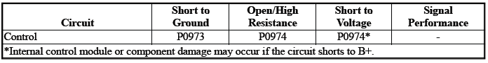
Typical Scan Tool Data
Shift Solenoid Valve 1
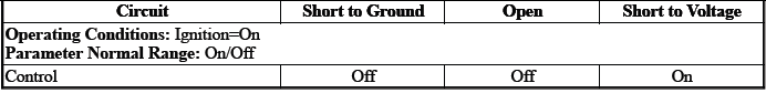
Shift Solenoid Valve 1 Control Circuit High Voltage Test Status
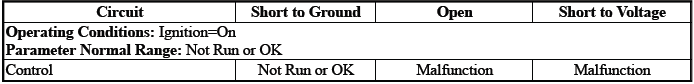
Shift Solenoid Valve 1 Control Circuit Low Voltage Test Status
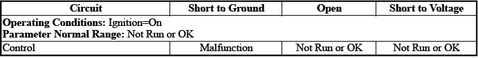
Shift Solenoid Valve 1 Control Circuit Open Test Status
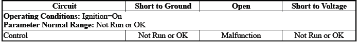
Circuit/System Description
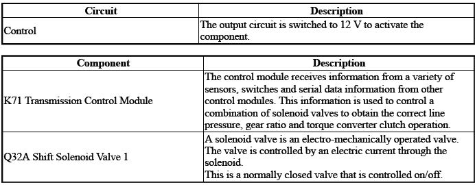
Depending on the state of the pressure control solenoids, the position of the component Q32A will cause either a gear shift or 1st gear engine braking.
Conditions for Running the DTC
Ignition Voltage=9 to 32 V
Frequency the DTC runs=Continuously - After the running conditions are met - For 2 s
Conditions for Setting the DTC
Control Circuit=Commanded state does not match the actual state
Actions Taken When the DTC Sets
DTCs listed in the DTC Descriptor Category=Type A DTC
- Fail-Safe Mode=Active
- Learning=Disabled
- Transmission gear allowed=3rd Gear - After a stop
Conditions for Clearing the DTC
DTCs listed in the DTC Descriptor Category=Type A DTC
Reference Information
Schematic: Reference
Refer to Automatic Transmission Controls Wiring Schematics.
Connector End View: Reference
Refer to Component Connector End View Index
Component View: Reference
Refer to Disassembled Views.
Description and Operation
Refer to Transmission General Description.
Electrical Information: Reference
- Refer to Circuit Testing
- Refer to Connector Repairs
- Refer to Testing for Intermittent Conditions and Poor Connections
- Refer to Wiring Repairs
DTC Type: Reference
Refer to Powertrain Diagnostic Trouble Code (DTC) Type Definitions.
Scan Tool: Reference
Refer to Control Module: References.
Circuit/System Verification
1. Engine - Running.
2. Perform the scan tool control function:Shift Transmission Gear - Upshift & Downshift.
Verify the scan tool parameter:
- Shift Solenoid Valve 1 Control Circuit High Voltage Test Status=Not Run or OK
- Shift Solenoid Valve 1 Control Circuit Low Voltage Test Status=Not Run or OK
- Shift Solenoid Valve 1 Control Circuit Open Test Status=Not Run or OK
- If not the specified state
Refer to Circuit/System Testing
- Go to next step: If the specified state
3. Perform the scan tool control function:Shift Solenoid Valve 1 - Enable & Disable
Verify the component produces a clicking sound:Q32A Shift Solenoid Valve 1
- If the component does not produce a sound
Refer to Circuit/System Testing
- Go to next step: If the component produces a sound
4. Operate the vehicle within the Conditions for Running the DTC. You may also operate the vehicle within the conditions that you observed from the Freeze Frame/Failure Records data.
Verify the DTC does not set.
- If the DTC sets
Refer to Circuit/System Testing
- Go to next step: If the DTC is not set
5. All OK.
Circuit/System Testing
1. Ignition/Vehicle - Off.
2. Remove the component:K71 Transmission Control Module.
NOTE: The component's temperature should be 19 to 21ºC (66 to 70ºF) while testing.
3. Test for 11 to 15 ohms between the test points:Control circuit terminal 23 X2 & Transmission Case
- If not between 11 and 15 ohms
- Remove the component:Control Valve Body Cover
- Disconnect the electrical connector:Q32A Shift Solenoid Valve 1
- Test for less than 2 ohms between the test points:Control circuit
terminal 1@Component harness &
Terminal 23 X2@Control module harness
- If greater than 2 ohms - Replace the component:Automatic Transmission Wiring Harness
- If less than 2 ohms - Replace the component:Control Valve Body
- Go to next step: If between 11 and 15 ohms
4. Replace the component:K71 Transmission Control Module
Component Testing
1. Ignition/Vehicle - Off.
2. Disconnect the electrical connector:Q32A Shift Solenoid Valve 1.
NOTE: The component's temperature should be 19 to 21ºC (66 to 70ºF) while testing.
3. Test for 11 to 15 ohms between the test points:Control terminal 1 & Transmission Case
- If not between 11 and 15 ohms
Replace the component:Control Valve Body
- Go to next step: If between 11 and 15 ohms
4. All OK.
Repair Instructions
Perform the Diagnostic Repair Verification after completing the repair: Refer to Diagnostic Repair Verification
- Refer to Control Valve Body Replacement
- Refer to Wiring Harness Wire Replacement
- For control module replacement, programming, and setup: Refer to Control Module: References
DTC P0976 or P0977
Diagnostic Instructions
- Perform the Diagnostic System Check prior to using this diagnostic procedure: Refer to Diagnostic System Check - Vehicle
- Review the description of Strategy Based Diagnosis: Refer to Strategy Based Diagnosis
- An overview of each diagnostic category can be found here: Refer to Diagnostic Procedure Instructions
DTC Descriptor
DTC P0976
Shift Solenoid Valve 2 Control Circuit Low Voltage
DTC P0977
Shift Solenoid Valve 2 Control Circuit High Voltage
Diagnostic Fault Information
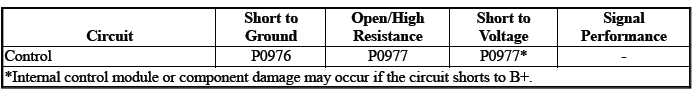
Typical Scan Tool Data
Shift Solenoid Valve 2 Control Circuit High Voltage Test Status
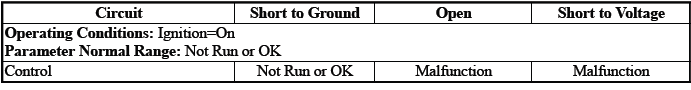
Shift Solenoid Valve 2 Control Circuit Low Voltage Test Status
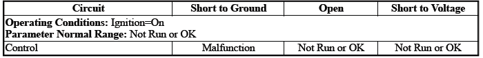
Shift Solenoid Valve 2 Control Circuit Open Test Status
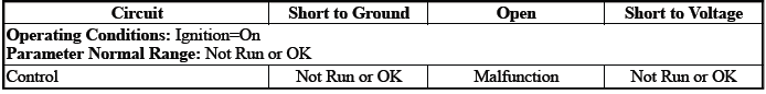
Circuit/System Description
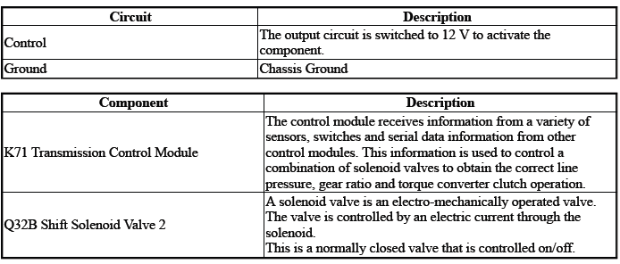
Depending on the state of the linear solenoids, the position of the Q32B will cause either a gear shift or 1st gear engine braking.
Conditions for Running the DTC
Ignition Voltage=9 to 32 V
Frequency the DTC runs=Continuously - After the running conditions are met - For 2 s
Conditions for Setting the DTC
P0976
Shift Solenoid Valve 2 Control Circuit=Off & Shift Solenoid Valve 2 Command=On - For greater than 5 s
P0977
Shift Solenoid Valve 2 Control Circuit=On & Shift Solenoid Valve 2 Command=Off - For greater than 5 s
Actions Taken When the DTC Sets
DTCs listed in the DTC Descriptor Category=Type B DTC
- Learning=Disabled
- Fail-Safe Mode=Active
- Transmission gear allowed=3rd Gear - After a stop
Conditions for Clearing the DTC
DTCs listed in the DTC Descriptor Category=Type B DTC
Reference Information
Schematic: Reference
Refer to Automatic Transmission Controls Wiring Schematics.
Connector End View: Reference
Refer to Component Connector End View Index.
Component View: Reference
Refer to Disassembled Views.
Description and Operation
Refer to Transmission General Description.
Electrical Information: Reference
- Refer to Circuit Testing
- Refer to Connector Repairs
- Refer to Testing for Intermittent Conditions and Poor Connections
- Refer to Wiring Repairs
DTC Type: Reference
Refer to Powertrain Diagnostic Trouble Code (DTC) Type Definitions.
Scan Tool: Reference
Refer to Control Module: References.
Circuit/System Verification
1. Engine - Running
2. Perform the scan tool control function:Pressure Control Solenoid Valve 2 - Increase & Decrease
Verify the scan tool parameter:
- Shift Solenoid Valve 2 Control Circuit High Voltage Test Status=Not Run or OK
- Shift Solenoid Valve 2 Control Circuit Low Voltage Test Status=Not Run or OK
- Shift Solenoid Valve 2 Control Circuit Open Test Status=Not Run or OK
- If not the specified state
Refer to Circuit/System Testing
- Go to next step: If the specified state
3. Perform the scan tool control function:Pressure Control Solenoid Valve 2 - Increase & Decrease Verify the component produces a clicking sound:Q32B Shift Solenoid Valve 2=On and Off
- If the component does not produce a sound
Refer to Circuit/System Testing
- Go to next step: If the component produces a sound
4. Operate the vehicle within the Conditions for Running the DTC. You may also operate the vehicle within the conditions that you observed from the Freeze Frame/Failure Records data.
Verify the DTC does not set.
- If the DTC sets
Refer to Circuit/System Testing
- Go to next step: If the DTC is not set
5. All OK.
Circuit/System Testing
NOTE: It may take up to 2 min for all vehicle systems to power down before an accurate ground or low reference circuit continuity test can be performed.
1. Ignition/Vehicle & All vehicle systems - Off.
2. Remove the component:K71 Transmission Control Module.
NOTE: The component's temperature should be 19 to 21ºC (66 to 70ºF) while testing.
3. Test for 11 to 15 ohms between the test points:Control circuit terminal 28 & Transmission Case
- If not between 11 and 15 ohms
- Remove the component:Control Valve Body Cover
- Disconnect the electrical connector:Q32B Shift Solenoid Valve 2
- Test for less than 2 ohms between the test points:Control circuit terminal 28@Control module harness & Control circuit terminal 1@Component harness
- If greater than 2 ohms - Replace the component:Automatic Transmission Wiring Harness
- If less than 2 ohms - Replace the component:Control Valve Body
- Go to next step: If between 11 and 15 ohms
4. Replace the component:K71 Transmission Control Module
Component Testing
1. Ignition/Vehicle - Off
2. Disconnect the electrical connector:Q32B Shift Solenoid Valve 2
NOTE: The component's temperature should be 19 to 21ºC (66 to 70ºF) while testing.
3. Test for 11 to 15 ohms between the test points:Control terminal 1 & Transmission Case
- If not between 11 and 15 ohms
Replace the component:Control Valve Body
- Go to next step: If between 11 and 15 ohms
4. All OK.
Repair Instructions
Perform the Diagnostic Repair Verification after completing the repair: Refer to Diagnostic Repair Verification
- Refer to Control Valve Body Replacement
- Refer to Wiring Harness Wire Replacement
- For control module replacement, programming, and setup: Refer to Control Module: References
DTC P170A-P170E
Diagnostic Instructions
- Perform the Diagnostic System Check prior to using this diagnostic procedure: Refer to Diagnostic System Check - Vehicle
- Review the description of Strategy Based Diagnosis:Strategy Based Diagnosis
- An overview of each diagnostic category can be found here: Refer to Diagnostic Procedure Instructions
DTC Descriptor
DTC P170A
Transmission Hydraulic Circuit 2 Max Pressure Not Achieved
DTC P170B
Transmission Hydraulic Circuit 3 Max Pressure Not Achieved
DTC P170C
Transmission Hydraulic Circuit 4 Max Pressure Not Achieved
DTC P170D
Transmission Hydraulic Circuit 5 Max Pressure Not Achieved
DTC P170E
Transmission Hydraulic Circuit 6 Max Pressure Not Achieved
Circuit/System Description
The pressure control solenoid valves control fluid pressure to the C1, 2, 3, 4 and B1 clutches. The respective pressures were not reached when the transmission experienced an abnormal upshift/downshift or a tie-up during shifts.
Conditions for Running the DTC
- DTC P0563, P0601, P0602, P0604, P0711, P0712, P0713, P0717, P07BF, P07C0, P0722, P0748, P077C, P077D, P0778, P0798, P0962, P0963, P0966, P0967, P0970, P0971, P2716, P2720, P2721, P2725, P2729, P2730, P2734, P2738, P2739 = Not set
- Ignition=On
- Battery Voltage=9 to 32 V - For greater than 2 s
- Engine Speed=Greater than 400 RPM
- Transmission Range= Drive
- Transmission Fluid Temperature=Warmer than -20ºC (4ºF)
- Garage Shift =No
- Transmission OSS=Greater than 300 RPM
- Slip Detected=No
- Accelerator Pedal=Greater than 70%
- Engine Torque =Greater than 70 Nm (52 lb ft)
- Transmission OSS=300 to 3000 RPM
- Transmission OSS=Less than -50 RPM per second
Conditions for Setting the DTC
Condition 1
Clutch C1, C2, C3, C4, B1=Not released
Condition 2
Incorrect gear ratio@Current Gear - More than 5 times.
Actions Taken When the DTC Sets
DTCs listed in the DTC Descriptor Category=Type A DTC
Fail-Safe Mode=Active
Conditions for Clearing the DTC
DTCs listed in the DTC Descriptor Category=Type A DTC
Reference Information
Schematic: Reference
Refer to Automatic Transmission Controls Wiring Schematics
Connector End View: Reference
- Refer to Component Connector End View Index
- Refer to Inline Harness Connector End View Index
Component View: Reference
Refer to Disassembled Views.
Description and Operation
- Refer to Electronic Component Description Refer to Transmission General Description
Electrical Information: Reference
- Refer to Circuit Testing
- Refer to Connector Repairs
- Refer to Testing for Intermittent Conditions and Poor Connections
- Refer to Wiring Repairs
DTC Type: Reference
Refer to Powertrain Diagnostic Trouble Code (DTC) Type Definitions.
Scan Tool: Reference
Refer to Control Module: References.
Circuit/System Verification
1. Ignition - On / Vehicle - In Service Mode
2. Verify there are no DTCs set related to the following system/component:
- Q27A Pressure Control Solenoid Valve 1
- Q27B Pressure Control Solenoid Valve 2
- Q27C Pressure Control Solenoid Valve 3
- Q27D Pressure Control Solenoid Valve 4
- Q27E Pressure Control Solenoid Valve 5
- If other DTCs are set
Refer to: Diagnostic Trouble Code (DTC) List - Vehicle
- Go to next step: If no other DTCs are set
3. Verify the condition does not exist:Incorrect fluid level or condition. Refer to Transmission Fluid Level and Condition Check.
- If a condition exists
Repair or replace as necessary.
- Go to next step: If no condition exists
4. Verify there are no DTCs set related to the following system/component:K173 Transmission Range Control Module
- If any DTC is set
Refer to: Diagnostic Trouble Code (DTC) List - Vehicle
- Go to next step: If no DTC is set
5. Clear the DTCs.
6. Perform the configuration/reset function: Refer to Learned Values Reset.
7. Road test the vehicle. Refer to Road Test.
8. Verify DTC P170A, P170B, P170C, P170D, P170E is not set.
- {Test failed 1 time (s) }If any of the DTCs are set
- Replace the component: Control Valve Body
- Refer to:Step 5
- {Test failed 2 time (s) }If any of the DTCs are set
- Replace the component: K71 Transmission Control Module
- Refer to:Step 5
- {Test failed 3 time (s) }If any of the DTCs are set
- Replace the component: T12 Automatic Transmission Assembly
- Refer to:Step 5
- Go to next step: If none of the DTCs are set
9. Operate the vehicle within the Conditions for Running the DTC. You may also operate the vehicle within the conditions that you observed from the Freeze Frame/Failure Records data.
10. Verify the DTC does not set.
- If the DTC sets
Refer to:Step 1
- Go to next step: If the DTC is not set
11. All OK.
Repair Instructions
Perform the Diagnostic Repair Verification after completing the repair: Refer to Diagnostic Repair Verification
- Refer to Control Valve Body Replacement
- Refer to Transmission Replacement
- For control module replacement, programming, and setup: Refer to Control Module: References
DTC P175F
Diagnostic Instructions
- Perform the Diagnostic System Check prior to using this diagnostic procedure: Refer to Diagnostic System Check - Vehicle
- Review the description of Strategy Based Diagnosis:Strategy Based Diagnosis
- An overview of each diagnostic category can be found here: Refer to Diagnostic Procedure Instructions
DTC Descriptor
DTC P175F
Acceleration Sensor Signal Message Counter Incorrect
Circuit/System Description
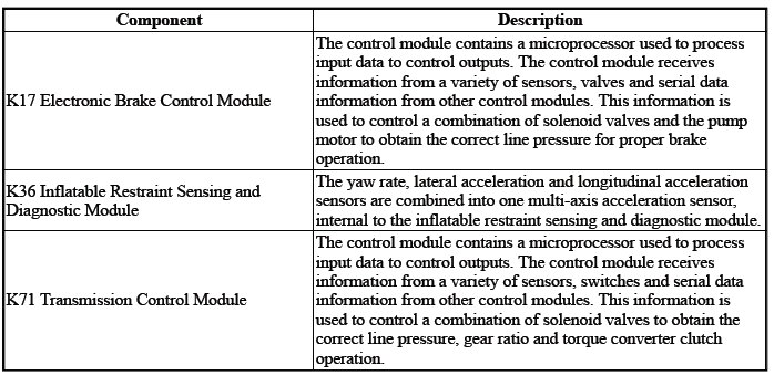
Inflatable Restraint Sensing and Diagnostic Module communicates with the electronic brake control module and transmission control module via serial data. The electronic brake control module activates the stability control function depending on the multi-axis acceleration sensor input. The inflatable restraint sensing and diagnostic module uses the multi-axis acceleration sensor to determine if the vehicle is in a roll over or near collision incident.
The transmission control module uses the rate of vehicle acceleration to improve vehicle performance and transmission shift feel. The transmission control module sets this DTC when it detects a discrepancy in the structure of the message, causing the signal message integrity to be questioned.
Conditions for Running the DTC
- DTC U0121 = Not set
- Ignition=On - For greater than 3 s
- Serial Data=Enabled
Frequency the DTC runs=Continuously - After the running conditions are met
Conditions for Setting the DTC
Serial Data=Message Counter Incorrect - Between the following control modules:
- K71 Transmission Control Module
- K17 Electronic Brake Control Module
The above condition (s) must occur 5 times.
Actions Taken When the DTC Sets
DTCs listed in the DTC Descriptor Category=Type C DTC
Conditions for Clearing the DTC
DTCs listed in the DTC Descriptor Category=Type C DTC
Reference Information
DTC Type: Reference
Refer to Powertrain Diagnostic Trouble Code (DTC) Type Definitions.
Scan Tool: Reference
Refer to Control Module: References.
Circuit/System Verification
1. Verify there are no DTCs set related to the following system/component:Serial Data
- If other DTCs are set
Refer to: Diagnostic Trouble Code (DTC) List - Vehicle
- If no other DTCs are set
- Replace the component:K71 Transmission Control Module
- Operate the vehicle within the Conditions for Running the DTC.
Verify the DTC does not set.
- If the DTC sets - Replace the component:K17 Electronic Brake Control Module
- Go to next step: If the DTC is not set
- All OK.
- Go to next step: If no DTC is set
2. All OK.
Repair Instructions
Perform the Diagnostic Repair Verification after completing the repair: Refer to Diagnostic Repair Verification
For control module replacement, programming, and setup: Refer to Control Module: References
DTC P1761
Diagnostic Instructions
- Perform the Diagnostic System Check prior to using this diagnostic procedure: Refer to Diagnostic System Check - Vehicle
- Review the description of Strategy Based Diagnosis:Strategy Based Diagnosis
- An overview of each diagnostic category can be found here: Refer to Diagnostic Procedure Instructions
DTC Descriptor
DTC P1761
Up and Down Shift Switch Signal Message Counter Incorrect
Circuit/System Description
Control modules connected to the serial data circuits monitor the communication during normal vehicle operation.
Operating information and commands are exchanged among the control modules. Each module on the serial data circuit maintains a transmit error counter and a receive error counter. The counter values increase with detected errors and decrease with error-free messages.
Conditions for Running the DTC
- K9 Body Control Module= Communication Enabled
- K71 Transmission Control Module= Communication Enabled
- Ignition Voltage=9 to 32 V
Frequency the DTC runs=Continuously - After the running conditions are met
Conditions for Setting the DTC
Serial Data=Message Counter Incorrect - Between the following control modules:
- K71 Transmission Control Module
- K9 Body Control Module
The above condition (s) must occur 5 times.
Actions Taken When the DTC Sets
- DTCs listed in the DTC Descriptor Category=Type C DTC
- Manual Shift Control=Disabled
Conditions for Clearing the DTC
DTCs listed in the DTC Descriptor Category=Type C DTC
Reference Information
DTC Type: Reference
Refer to Powertrain Diagnostic Trouble Code (DTC) Type Definitions.
Scan Tool: Reference
Refer to Control Module: References.
Circuit/System Verification
1. Verify there are no DTCs set related to the following system/component:Serial Data
- If other DTCs are set
Refer to: Diagnostic Trouble Code (DTC) List - Vehicle
- If no other DTCs are set
- Replace the component:K71 Transmission Control Module
- Operate the vehicle within the Conditions for Running the DTC.
Verify the DTC does not set.
- If the DTC sets - Replace the component:K9 Body Control Module
- Go to next step: If the DTC is not set
- All OK.
- Go to next step: If no DTC is set
2. All OK.
Repair Instructions
Perform the Diagnostic Repair Verification after completing the repair: Refer to Diagnostic Repair Verification
For control module replacement, programming, and setup: Refer to Control Module: References
DTC P1775
Diagnostic Instructions
- Perform the Diagnostic System Check prior to using this diagnostic procedure: Refer to Diagnostic System Check - Vehicle
- Review the description of Strategy Based Diagnosis:Strategy Based Diagnosis
- An overview of each diagnostic category can be found here: Refer to Diagnostic Procedure Instructions
DTC Descriptor
DTC P1775
Transmission Range Request Signal Message Counter Incorrect
Circuit/System Description
For an overview of the component/system, refer to Electronic Component Description
Control modules connected to the serial data circuits monitor the communication during normal vehicle operation.
Operating information and commands are exchanged among the control modules. Each module on the serial data circuit maintains a transmit error counter and a receive error counter. The counter values increase with detected errors and decrease with error-free messages.
Conditions for Running the DTC
- Battery Voltage=9 to 32 V
- Ignition Voltage =9 to 32 V
- No other DTCs related to the concerned component are set.
Conditions for Setting the DTC
Serial Data=Message Counter Incorrect - Between the following control modules:
- K9 Body Control Module
- K71 Transmission Control Module
Actions Taken When the DTC Sets
DTCs listed in the DTC Descriptor Category=Type B DTC
Conditions for Clearing the DTC
DTCs listed in the DTC Descriptor Category=Type B DTC
Reference Information
DTC Type: Reference
Refer to Powertrain Diagnostic Trouble Code (DTC) Type Definitions.
Scan Tool: Reference
Refer to Control Module: References.
Circuit/System Verification
NOTE: DTC P1775 is an informational DTC.
1. Ignition - On / Vehicle - In Service Mode
2. Verify there are no DTCs set related to the following system/component:Serial Data
- If a related DTC is set
Refer to: Diagnostic Trouble Code (DTC) List - Vehicle
- Go to next step: If a related DTC is not set
- Ignition/Vehicle - Off
- Replace the component:K71 Transmission Control Module
- Operate the vehicle within the Conditions for Running the DTC.
- Verify the DTC does not set.
- If the DTC sets - Replace the component:K9 Body Control Module
- Go to next step: If the DTC is not set
- All OK.
- Go to next step: If no DTC is set
3. All OK.
Repair Instructions
Perform the Diagnostic Repair Verification after completing the repair: Refer to Diagnostic Repair Verification.
For control module replacement, programming, and setup: Refer to Control Module: References.
DTC P2716, P2720, or P2721
Diagnostic Instructions
- Perform the Diagnostic System Check prior to using this diagnostic procedure: Refer to Diagnostic System Check - Vehicle
- Review the description of Strategy Based Diagnosis: Refer to Strategy Based Diagnosis
- An overview of each diagnostic category can be found here: Refer to Diagnostic Procedure Instructions
DTC Descriptor
DTC P2716
Pressure Control Solenoid Valve 4 Control Circuit
DTC P2720
Pressure Control Solenoid Valve 4 Control Circuit Low Voltage
DTC P2721
Pressure Control Solenoid Valve 4 Control Circuit High Voltage
Diagnostic Fault Information
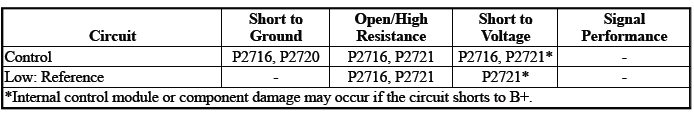
Typical Scan Tool Data
Pressure Control Solenoid Valve 4 Control Circuit High Voltage Test Status
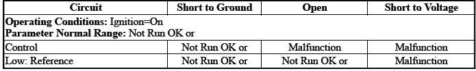
Pressure Control Solenoid Valve 4 Control Circuit Low Voltage Test Status
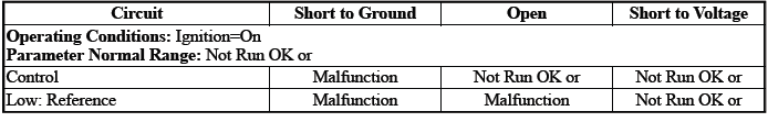
Pressure Control Solenoid Valve 4 Control Circuit Open Test Status
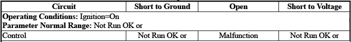

Circuit/System Description
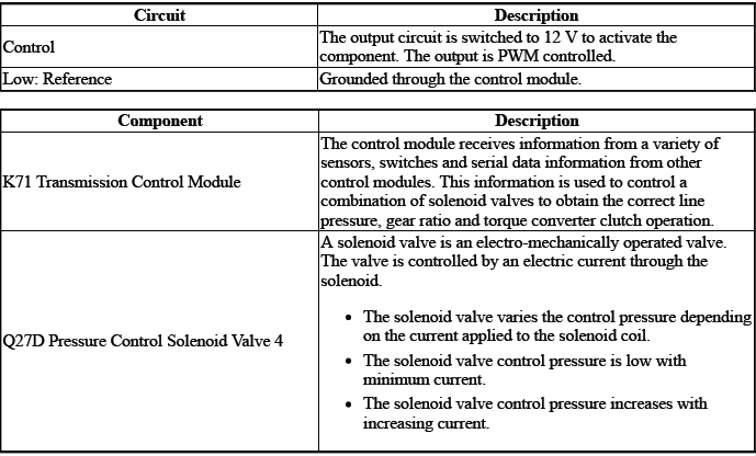
The solenoid valve controls the flow of transmission fluid to the hydraulic actuator that controls the C4 clutch.
Conditions for Running the DTC
- { P2716 }DTC P0606, P0657, P0962, P0963, P0966, P0967, P0970, P0971, P2720, P2721, P2729, P2730, P2738, P2739 = Not set
- { P2720 }DTC P0606, P0657, P0963, P0967, P0971, P2721, P2730, P2739 = Not set
- { P2721 }DTC P0606, P0657, P0962, P0966, P0970, P2720, P2729, P2738, = Not set
- Ignition Voltage=9 to 32 V
Frequency the DTC runs=Continuously - After the running conditions are met
Conditions for Setting the DTC
P2716
Control Circuit=Commanded state does not match the actual state
P2720
Control Circuit=Less than 20 mA - For greater than 1 s
P2721
Control Circuit=Greater than 1358 mA - For greater than 1 s
Actions Taken When the DTC Sets
DTCs listed in the DTC Descriptor Category=Type A DTC
- Fail-Safe Mode=Active
- Learning=Disabled
- Transmission gear allowed=3rd Gear - After a stop
Conditions for Clearing the DTC
DTCs listed in the DTC Descriptor Category=Type A DTC
Reference Information
Schematic: Reference
Refer to Automatic Transmission Controls Wiring Schematics.
Connector End View: Reference
Refer to Component Connector End View Index.
Component View: Reference
Refer to Disassembled Views.
Description and Operation
Refer to Transmission General Description.
Electrical Information: Reference
- Refer to Circuit Testing
- Refer to Connector Repairs
- Refer to Testing for Intermittent Conditions and Poor Connections
- Refer to Wiring Repairs
DTC Type: Reference
Refer to Powertrain Diagnostic Trouble Code (DTC) Type Definitions
Scan Tool: Reference
Refer to Control Module: References
Circuit/System Verification
1. Ignition - On / Vehicle - In Service Mode
2. Perform the scan tool control function:Pressure Control Solenoid Valve 4 - Increase & Decrease
Verify the scan tool parameter:
- Pressure Control Solenoid Valve 4 Control Circuit High Voltage Test Status=Not Run or OK
- Pressure Control Solenoid Valve 4 Control Circuit Low Voltage Test Status=Not Run or OK
- Pressure Control Solenoid Valve 4 Control Circuit Open Test Status=Not Run or OK
- If not the specified state
Refer to Circuit/System Testing
- Go to next step: If the specified state
3. Perform the scan tool control function:Pressure Control Solenoid Valve 4 - Increase & Decrease Verify the component produces a clicking sound:Q27D Pressure Control Solenoid Valve 4
- If the component does not produce a sound
Refer to Circuit/System Testing
- Go to next step: If the component produces a sound
4. Operate the vehicle within the Conditions for Running the DTC. You may also operate the vehicle within the conditions that you observed from the Freeze Frame/Failure Records data.
Verify the DTC does not set.
- If the DTC sets
Refer to Circuit/System Testing
- Go to next step: If the DTC is not set
5. All OK.
Circuit/System Testing
NOTE: It may take up to 2 min for all vehicle systems to power down before an accurate ground or low reference circuit continuity test can be performed.
1. Ignition/Vehicle & All vehicle systems - Off
NOTE: Twisting or tilting of the transmission control module electrical connector while disconnecting may result in bent or misaligned electrical terminal pins.
2. Remove the component:K71 Transmission Control Module
3. Test for 5.0 to 5.6 ohms between the test points:Control circuit terminal 21 & Low: Reference circuit terminal 22
- If not between 5.0 and 5.6 ohms
- Remove the component:Control Valve Body Cover
- Disconnect the electrical connector:Q27D Pressure Control Solenoid Valve 4
- Test for less than 2 ohms between the test points:
- Control circuit terminal 2@Component harness & Control circuit terminal 21@Control module harness
- Low: Reference circuit terminal 1@Component harness & Low: Reference circuit terminal 22@Control module harness
- If 2 ohms or greater - Replace the component:Automatic Transmission Wiring Harness
- If less than 2 ohms - Replace the component:Q27D Pressure Control Solenoid Valve 4
- Go to next step: If between 5.0 and 5.6 ohms
4. Test for infinite resistance between the test points:
- Control circuit terminal 21 & Transmission Case
- Low: Reference circuit terminal 22 & Transmission Case
- If less than infinite resistance
- Remove the component:Control Valve Body Cover
- Disconnect the electrical connector:Q27D Pressure Control Solenoid Valve 4
- Test for infinite resistance between the test points:
- Control circuit terminal 2@Component harness & Transmission Case
- Low: Reference circuit terminal 1@Component harness & Transmission Case
- If less than infinite resistance - Replace the component:Automatic Transmission Wiring Harness
- If infinite resistance - Replace the component:Control Valve Body
- Go to next step: If infinite resistance
5. Replace the component:K71 Transmission Control Module
Component Testing
1. Ignition/Vehicle - Off
2. Disconnect the electrical connector:Q27D Pressure Control Solenoid Valve 4
NOTE: The component's temperature should be 19 to 21ºC (66 to 70ºF) while testing.
3. Test for 5.0 to 5.6 ohms between the test points:Control terminal 2 & Low: Reference terminal 1
- If not between 5.0 and 5.6 ohms
Replace the component:Control Valve Body
- Go to next step: If between 5.0 and 5.6 ohms
4. Test for infinite resistance between the test points:Each terminal of the component & The component's housing
- If less than infinite resistance
Replace the component:Control Valve Body
- Go to next step: If infinite resistance
5. All OK.
Repair Instructions
Perform the Diagnostic Repair Verification after completing the repair: Refer to Diagnostic Repair Verification
- Refer to Control Valve Body Replacement
- Refer to Wiring Harness Wire Replacement
- For control module replacement, programming, and setup: Refer to Control Module: References
DTC P2725, P2729, or P2730
Diagnostic Instructions
- Perform the Diagnostic System Check prior to using this diagnostic procedure: Refer to Diagnostic System Check - Vehicle
- Review the description of Strategy Based Diagnosis: Refer to Strategy Based Diagnosis
- An overview of each diagnostic category can be found here: Refer to Diagnostic Procedure Instructions
DTC Descriptor
DTC P2725
Pressure Control Solenoid Valve 5 Control Circuit
DTC P2729
Pressure Control Solenoid Valve 5 Control Circuit Low Voltage
DTC P2730
Pressure Control Solenoid Valve 5 Control Circuit High Voltage
Diagnostic Fault Information
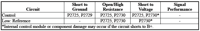
Typical Scan Tool Data
Pressure Control Solenoid Valve 5 Control Circuit High Voltage Test Status
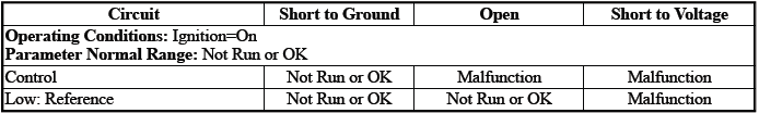
Pressure Control Solenoid Valve 5 Control Circuit Low Voltage Test Status
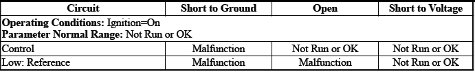
Pressure Control Solenoid Valve 5 Control Circuit Open Test Status
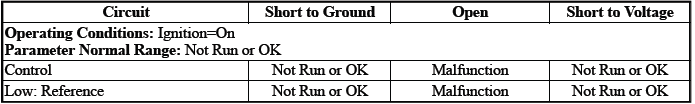
Circuit/System Description
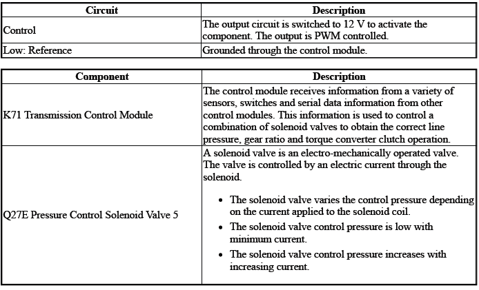
The solenoid valve controls the flow of transmission fluid to the hydraulic actuator that controls the C5 clutch.
Conditions for Running the DTC
P2725
- { P2725 }DTC P0606, P0657, P0962, P0963, P0966, P0967, P0970, P0971, P2720, P2721, P2729, P2730, P2738, P2739 = Not set
- { P2729 }DTC P0606, P0657, P0963, P0967, P0971, P2721, P2730, P2739 = Not set
- { P2730 }DTC P0606, P0657, P0962, P0966, P0970, P2720, P2729, P2738, = Not set
- Ignition Voltage=9 to 32 V
Frequency the DTC runs=Continuously - After the running conditions are met
Conditions for Setting the DTC
P2725
Control Circuit=Commanded state does not match the actual state
P2729
Control Circuit=Less than 20 mA - For greater than 1 s
P2730
Control Circuit=Greater than 1358 mA - For greater than 1 s
Actions Taken When the DTC Sets
DTCs listed in the DTC Descriptor Category=Type A DTC
- Fail-Safe Mode=Active
- Learning=Disabled
- Transmission gear allowed=3rd Gear - After a stop
Conditions for Clearing the DTC
DTCs listed in the DTC Descriptor Category=Type A DTC
Reference Information
Schematic: Reference
Refer to Automatic Transmission Controls Wiring Schematics
Connector End View: Reference
Refer to Component Connector End View Index
Component View: Reference
Refer to Disassembled Views
Description and Operation
Refer to Transmission General Description
Electrical Information: Reference
- Refer to Circuit Testing
- Refer to Connector Repairs
- Refer to Testing for Intermittent Conditions and Poor Connections
- Refer to Wiring Repairs
DTC Type: Reference
Refer to Powertrain Diagnostic Trouble Code (DTC) Type Definitions
Scan Tool: Reference
Refer to Control Module: References
Circuit/System Verification
1. Ignition - On / Vehicle - In Service Mode
2. Perform the scan tool control function:Pressure Control Solenoid Valve 5 - Increase & Decrease
Verify the scan tool parameter:
- Pressure Control Solenoid Valve 5 Control Circuit High Voltage Test Status=Not Run or OK
- Pressure Control Solenoid Valve 5 Control Circuit Low Voltage Test Status=Not Run or OK
- Pressure Control Solenoid Valve 5 Control Circuit Open Test Status=Not Run or OK
- If not the specified state
- Refer to Circuit/System Testing
- Go to next step: If the specified state
3. Perform the scan tool control function:Pressure Control Solenoid Valve 5 - Enable & Disable
Verify the component produces a clicking sound:Q27E Pressure Control Solenoid Valve 5
- If the component does not produce a sound
Refer to Circuit/System Testing
- Go to next step: If the component produces a sound
4. Operate the vehicle within the Conditions for Running the DTC. You may also operate the vehicle within the conditions that you observed from the Freeze Frame/Failure Records data.
Verify the DTC does not set.
- If the DTC sets
Refer to Circuit/System Testing
- Go to next step: If the DTC is not set
5. All OK.
Circuit/System Testing
NOTE: It may take up to 2 min for all vehicle systems to power down before an accurate ground or low reference circuit continuity test can be performed.
1. Ignition/Vehicle & All vehicle systems - Off
NOTE: Twisting or tilting of the transmission control module electrical connector while disconnecting may result in bent or misaligned electrical terminal pins.
2. Disconnect the electrical connector:X2@K71 Transmission Control Module
3. Test for 5.0 to 5.6 ohms between the test points:Control circuit terminal 5 & Low: Reference circuit terminal 12@Control module harness
- If not between 5.0 and 5.6 ohms
- Remove the component:Control Valve Body Cover
- Disconnect the electrical connector:Q27E Pressure Control Solenoid Valve 5
- Test for less than 2 ohms between the test points:
- Control circuit terminal 2@Component harness & Control circuit terminal 5@Control module harness
- Low: Reference circuit terminal 1@Component harness & Low: Reference circuit terminal 12@Control module harness
- If 2 ohms or greater - Replace the component:Automatic Transmission Wiring Harness
- If less than 2 ohms - Replace the component:Q27E Pressure Control Solenoid Valve 5
- Go to next step: If between 5.0 and 5.6 ohms
4. Test for infinite resistance between the test points:
- Control circuit terminal 5 & Transmission Case
- Low: Reference circuit terminal 12 & Transmission Case
- If less than infinite resistance
- Remove the component:Control Valve Body Cover
- Disconnect the electrical connector:Q27E Pressure Control Solenoid Valve 5
- Test for infinite resistance between the test points:
- Control circuit terminal 2@Component harness & Transmission Case
- Low: Reference circuit terminal 1@Component harness & Transmission Case
- If less than infinite resistance - Replace the component:Automatic Transmission Wiring Harness
- If infinite resistance - Replace the component:Control Valve Body
- Go to next step: If infinite resistance
5. Replace the component:K71 Transmission Control Module
Component Testing
1. Ignition/Vehicle - Off
2. Disconnect the electrical connector:Q27E Pressure Control Solenoid Valve 5
NOTE: The component's temperature should be 19 to 21ºC (66 to 70ºF) while testing.
3. Test for 5.0 to 5.6 ohms between the test points:Control terminal 2 & Low: Reference terminal 1
- If not between 5.0 and 5.6 ohms
Replace the component:Control Valve Body
- Go to next step: If between 5.0 and 5.6 ohms
4. Test for infinite resistance between the test points:Each terminal of the component & The component's housing
- If less than infinite resistance
Replace the component:Control Valve Body
- Go to next step: If infinite resistance
5. All OK.
Repair Instructions
Perform the Diagnostic Repair Verification after completing the repair: Refer to Diagnostic Repair Verification
- Refer to Control Valve Body Replacement
- Refer to Wiring Harness Wire Replacement
- For control module replacement, programming, and setup: Refer to Control Module: References
DTC P2734, P2738, or P2739
Diagnostic Instructions
- Perform the Diagnostic System Check prior to using this diagnostic procedure: Refer to Diagnostic System Check - Vehicle
- Review the description of Strategy Based Diagnosis: Refer to Strategy Based Diagnosis
- An overview of each diagnostic category can be found here: Refer to Diagnostic Procedure Instructions
DTC Descriptor
DTC P2734
Pressure Control Solenoid Valve 6 Control Circuit
DTC P2738
Pressure Control Solenoid Valve 6 Control Circuit Low Voltage
DTC P2739
Pressure Control Solenoid Valve 6 Control Circuit High Voltage
Diagnostic Fault Information
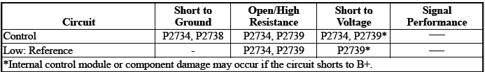
Typical Scan Tool Data
Pressure Control Solenoid Valve 6 Control Circuit High Voltage Test Status
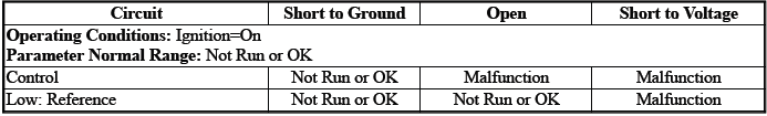
Pressure Control Solenoid Valve 6 Control Circuit Low Voltage Test Status

Pressure Control Solenoid Valve 6 Control Circuit Open Test Status

Circuit/System Description
For an overview of the component/system, refer to Transmission General Description
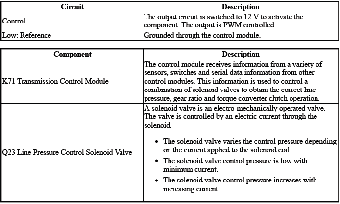
The solenoid valve controls line fluid pressure to the various pressure regulating valves in the transmission.
Conditions for Running the DTC
- { P2734 }DTC P0606, P0657, P0962, P0963, P0966, P0967, P0970, P0971, P2720, P2721, P2729, P2730, P2738, P2739 = Not set
- { P2738 }DTC P0606, P0657, P0963, P0967, P0971, P2721, P2730, P2739 = Not set
- { P2739 }DTC P0606, P0657, P0962, P0966, P0970, P2720, P2729, P2738, = Not set
- Ignition Voltage=9 to 32 V
Frequency the DTC runs=Continuously - After the running conditions are met
Conditions for Setting the DTC
P2734
Control Circuit=Commanded state does not match the actual state
P2738
Control Circuit=Less than 20 mA - For greater than 1 s
P2739
Control Circuit=Greater than 1358 mA - For greater than 1 s
Actions Taken When the DTC Sets
DTCs listed in the DTC Descriptor Category=Type A DTC
- Fail-Safe Mode=Fail-Safe Mode
- Learning=Disabled
- Transmission gear allowed=3rd Gear - After a stop
Conditions for Clearing the DTC
DTCs listed in the DTC Descriptor Category=Type A DTC
Reference Information
Schematic: Reference
Refer to Automatic Transmission Controls Wiring Schematics
Connector End View: Reference
Refer to Component Connector End View Index
Component View: Reference
Refer to Disassembled Views
Electrical Information: Reference
- Refer to Circuit Testing
- Refer to Connector Repairs
- Refer to Testing for Intermittent Conditions and Poor Connections
- Refer to Wiring Repairs
DTC Type: Reference
Refer to Powertrain Diagnostic Trouble Code (DTC) Type Definitions
Scan Tool: Reference
Refer to Control Module: References
Circuit/System Verification
1. Ignition - On / Vehicle - In Service Mode.
2. Perform the scan tool control function:Pressure Control Solenoid Valve 6 - Increase & Decrease.
Verify the scan tool parameter:
- Pressure Control Solenoid Valve 6 Control Circuit High Voltage Test Status=Not Run or OK
- Pressure Control Solenoid Valve 6 Control Circuit Low Voltage Test Status=Not Run or OK
- Pressure Control Solenoid Valve 6 Control Circuit Open Test Status=Not Run or OK
- If not the specified state
Refer to Circuit/System Testing
- Go to next step: If the specified state
3. Perform the scan tool control function:Pressure Control Solenoid Valve 6 - Increase & Decrease
Verify the component produces a clicking sound:Q23 Line Pressure Control Solenoid Valve
- If the component does not produce a sound
Refer to Circuit/System Testing
- Go to next step: If the component produces a sound
4. Operate the vehicle within the Conditions for Running the DTC. You may also operate the vehicle within the conditions that you observed from the Freeze Frame/Failure Records data.
Verify the DTC does not set.
- If the DTC sets
Refer to Circuit/System Testing
- Go to next step: If the DTC is not set
5. All OK.
Circuit/System Testing
1. Ignition/Vehicle & All vehicle systems - Off
NOTE: Twisting or tilting of the transmission control module electrical connector while disconnecting may result in bent or misaligned electrical terminal pins.
2. Remove the component:K71 Transmission Control Module
NOTE: The component's temperature should be 19 to 21ºC (66 to 70ºF) while testing.
3. Test for 5.0 to 5.6 ohms between the test points:Control circuit terminal 6 & Low: Reference circuit terminal 7
- If not between 5.0 and 5.6 ohms
- Remove the component:Control Valve Body Cover
- Disconnect the electrical connector:Q23 Line Pressure Control Solenoid Valve
- Test for less than 2 ohms between the test points:
- Control circuit terminal 2@Component harness & Control circuit terminal
6@Control module
harness
- Low: Reference circuit terminal 1@Component harness & Low: Reference circuit terminal 7@Control module harness
- If 2 ohms or greater - Replace the component:Automatic Transmission Wiring Harness
- If less than 2 ohms - Replace the component:Q23 Line Pressure Control Solenoid Valve
- Go to next step: If between 5.0 and 5.6 ohms
4. Test for infinite resistance between the test points:
- Control circuit terminal 6 & Transmission Case
- Low: Reference circuit terminal 7 & Transmission Case
- If less than infinite resistance
- Remove the component:Control Valve Body Cover
- Disconnect the electrical connector:Q23 Line Pressure Control Solenoid Valve
- Test for infinite resistance between the test points:
- Control circuit terminal 2@Component harness & Transmission Case
- Low: Reference circuit terminal 1@Component harness & Transmission Case
- If less than infinite resistance - Replace the component:Automatic Transmission Wiring Harness
- If infinite resistance - Replace the component:Control Valve Body
- Go to next step: If infinite resistance
5. Replace the component:K71 Transmission Control Module
Component Testing
1. Ignition/Vehicle - Off
2. Disconnect the electrical connector:Q27F Pressure Control Solenoid Valve 6
NOTE: The component's temperature should be 19 to 21ºC (66 to 70ºF) while testing.
3. Test for 5.0 to 5.6 ohms between the test points:Control terminal 2 & Low: Reference terminal 1
- If not between 5.0 and 5.6 ohms
Replace the component:Control Valve Body
- Go to next step: If between 5.0 and 5.6 ohms
4. Test for infinite resistance between the test points:Each terminal of the component & The component's housing
- If less than infinite resistance
Replace the component:Control Valve Body
- Go to next step: If infinite resistance
5. All OK.
Repair Instructions
Perform the Diagnostic Repair Verification after completing the repair: Refer to Diagnostic Repair Verification
- Refer to Control Valve Body Replacement
- Refer to Wiring Harness Wire Replacement
- For control module replacement, programming, and setup: Refer to Control Module: References
DTC P2761, P2763, or P2764
Diagnostic Instructions
- Perform the Diagnostic System Check prior to using this diagnostic procedure: Refer to Diagnostic System Check - Vehicle
- Review the description of Strategy Based Diagnosis: Refer to Strategy Based Diagnosis
- An overview of each diagnostic category can be found here: Refer to Diagnostic Procedure Instructions
DTC Descriptor
DTC P2761
Torque Converter Clutch (TCC) Pressure Control Solenoid Valve Control Circuit
DTC P2763
Torque Converter Clutch (TCC) Pressure Control Solenoid Valve Control Circuit High Voltage
DTC P2764
Torque Converter Clutch (TCC) Pressure Control Solenoid Valve Control Circuit Low Voltage
Diagnostic Fault Information
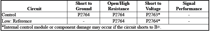
Typical Scan Tool Data
TCC Pressure Control Solenoid Valve Control Circuit High Voltage Test Status

TCC Pressure Control Solenoid Valve Control Circuit Low Voltage Test Status
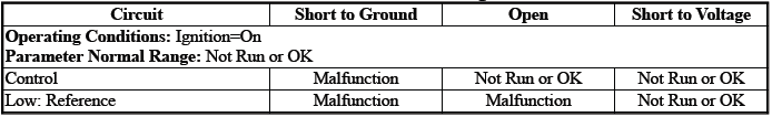
TCC Pressure Control Solenoid Valve Control Circuit Open Test Status
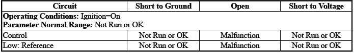
Circuit/System Description
For an overview of the component/system, refer to Transmission General Description
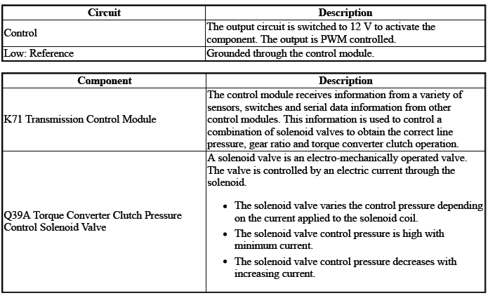
The solenoid valve controls the flow of transmission fluid to the hydraulic actuator that controls the torque converter clutch engagement.
Conditions for Running the DTC
- { P2761 }DTC P2763, P2764 = Not set
- { P2763 }DTC P2764 = Not set
- { P2764 }DTC P2763 = Not set
- Engine Speed= Greater than 400 RPM for greater than 2 s
- Fail-Safe Mode=Inactive
- Ignition Voltage=9 to 32 V
- K71 Transmission Control Module= Communication Enabled
- Transmission Range= Drive
Frequency the DTC runs=Continuously - After the running conditions are met
Conditions for Setting the DTC
P2761
Control Circuit=Commanded state does not match the actual state
P2763
Control Circuit=Less than 20 mA - For 1 s
P2764
Control Circuit=Greater than 1358 mA - For 1 s
Actions Taken When the DTC Sets
DTCs listed in the DTC Descriptor Category=Type B DTC
- { P2763 }Autostart/Autostop=Disabled - If equipped
- Learning=Disabled
- Transmission gear allowed=Gear 2 & Reverse - After a stop
Conditions for Clearing the DTC
DTCs listed in the DTC Descriptor Category=Type B DTC
Reference Information
Schematic: Reference
Refer to Automatic Transmission Controls Wiring Schematics
Connector End View: Reference
Refer to Component Connector End View Index
Component View: Reference
Refer to Disassembled Views
Electrical Information: Reference
- Refer to Circuit Testing
- Refer to Connector Repairs
- Refer to Testing for Intermittent Conditions and Poor Connections
- Refer to Wiring Repairs
DTC Type: Reference
Refer to Powertrain Diagnostic Trouble Code (DTC) Type Definitions
Scan Tool: Reference
Refer to Control Module: References
Circuit/System Verification
1. Ignition - On / Vehicle - In Service Mode
2. Perform the scan tool control function:TCC Solenoid Valve - On & Off
Verify the scan tool parameter:
- TCC Pressure Control Solenoid Valve Control Circuit High Voltage Test Status=Not Run or OK
- TCC Pressure Control Solenoid Valve Control Circuit Low Voltage Test Status=Not Run or OK
- TCC Pressure Control Solenoid Valve Control Circuit Open Test Status=Not Run or OK
- If not the specified state
Refer to Circuit/System Testing
- Go to next step: If the specified state
3. Perform the scan tool control function:TCC Solenoid Valve - Enable & Disable
Verify the component produces a clicking sound:Q39A Torque Converter Clutch Pressure Control Solenoid Valve
- If the component does not produce a sound
Refer to Circuit/System Testing
- Go to next step: If the component produces a sound
4. Operate the vehicle within the Conditions for Running the DTC. You may also operate the vehicle within the conditions that you observed from the Freeze Frame/Failure Records data.
Verify the DTC does not set.
- If the DTC sets
Refer to Circuit/System Testing
- Go to next step: If the DTC is not set
5. All OK.
Circuit/System Testing
NOTE: It may take up to 2 min for all vehicle systems to power down before an accurate ground or low reference circuit continuity test can be performed.
1. Ignition/Vehicle & All vehicle systems - Off
NOTE: Twisting or tilting of the transmission control module electrical connector while disconnecting may result in bent or misaligned electrical terminal pins.
2. Remove the component:K71 Transmission Control Module
3. Test for 5.0 to 5.6 ohms between the test points:Control circuit terminal 2 & Low: Reference circuit terminal 1
- If not between 5.0 and 5.6 ohms
- Remove the component:Control Valve Body Cover
- Disconnect the electrical connector:Q39A Torque Converter Clutch Pressure Control Solenoid Valve
- Test for less than 2 ohms between the test points:
- Control circuit terminal 2@Component harness & Control circuit terminal 2@Control module harness
- Low: Reference circuit terminal 1@Component harness & Low: Reference circuit terminal 1@Control module harness
- If 2 ohms or greater - Replace the component:Automatic Transmission Wiring Harness
- If less than 2 ohms - Replace the component:Control Valve Body
- Go to next step: If between 5.0 and 5.6 ohms
4. Test for infinite resistance between the test points:
- Control circuit terminal 2 & Transmission Case
- Low: Reference circuit terminal 1 & Transmission Case
- If less than infinite resistance
- Remove the component:Control Valve Body Cover
- Disconnect the electrical connector:Q39A Torque Converter Clutch Pressure Control Solenoid Valve
- Test for infinite resistance between the test points:
- Control circuit terminal 2@Component harness & Transmission Case
- Low: Reference circuit terminal 1@Component harness & Transmission Case
- If less than infinite resistance - Replace the component:Automatic Transmission Wiring Harness
- If infinite resistance - Replace the component:Control Valve Body
- Go to next step: If infinite resistance
5. Replace the component:K71 Transmission Control Module
Component Testing
1. Ignition/Vehicle - Off
2. Disconnect the electrical connector:Q39A Torque Converter Clutch Pressure Control Solenoid Valve
NOTE: The component's temperature should be 19 to 21ºC (66 to 70ºF) while testing.
3. Test for 5.0 to 5.6 ohms between the test points:Control terminal 2 & Low: Reference terminal 1
- If not between 5.0 and 5.6 ohms
Replace the component:Control Valve Body
- Go to next step: If between 5.0 and 5.6 ohms
4. Test for infinite resistance between the test points:Each terminal of the component & The component's housing
- If less than infinite resistance
Replace the component:Control Valve Body
- Go to next step: If infinite resistance
5. All OK.
Repair Instructions
Perform the Diagnostic Repair Verification after completing the repair: Refer to Diagnostic Repair Verification
- Refer to Control Valve Body Replacement
- Refer to Wiring Harness Wire Replacement
- For control module replacement, programming, and setup: Refer to Control Module: References
DTC P2808
Diagnostic Instructions
- Perform the Diagnostic System Check prior to using this diagnostic procedure: Refer to Diagnostic System Check - Vehicle
- Review the description of Strategy Based Diagnosis:Strategy Based Diagnosis
- An overview of each diagnostic category can be found here: Refer to Diagnostic Procedure Instructions
DTC Descriptor
DTC P2808
Pressure Control Solenoid Valve 7 Stuck Off - Hydraulic/Mechanical Problem
Circuit/System Description
The pressure control solenoid valve 7 is used to apply the C1 clutch during an autostop event. If the control module K71 detects the following conditions, DTC P2808 will set:
- Engine speed flare-up
- Incorrect gear ratio
Conditions for Running the DTC
- K71 Transmission Control Module=Communication Enabled
- Transmission Gear=1, 2, 3
- Transmission OSS=Less than 200 RPM
- Transmission Range=Drive
DTC runs continuously when the above conditions are met for greater than 2 s.
Conditions for Setting the DTC
Gear Ratio=Incorrect - More than 11 times.
Actions Taken When the DTC Sets
DTC P2808 is a Type C DTC.
Conditions for Clearing the DTC
DTC P2808 is a Type C DTC.
Reference Information
Schematic: Reference
Refer to Automatic Transmission Controls Wiring Schematics
Connector End View: Reference
Refer to Component Connector End View Index
Component View: Reference
Refer to Disassembled Views
Description and Operation
Refer to Transmission General Description
Electrical Information: Reference
- Refer to Circuit Testing
- Refer to Connector Repairs
- Refer to Testing for Intermittent Conditions and Poor Connections
- Refer to Wiring Repairs
DTC Type: Reference
Refer to Powertrain Diagnostic Trouble Code (DTC) Type Definitions
Scan Tool: Reference
Refer to Control Module: References
Circuit/System Verification
1. Ignition - On / Vehicle - In Service Mode.
2. Verify there are no DTCs set related to the following system/component:
- Transmission ISS
- Transmission OSS
- If other DTCs are set
Refer to: Diagnostic Trouble Code (DTC) List - Vehicle
- Go to next step: If no other DTCs are set
3. Verify the condition does not exist:Incorrect fluid level or condition. Refer to Transmission Fluid Level and Condition Check
- If a condition exists
Repair or replace as necessary.
- Go to next step: If no condition exists
4. Clear the DTCs.
5. Perform the configuration/reset function: Refer to Learned Values Reset.
6. Road test the vehicle. Refer to Road Test.
7. Verify DTC P2808 is not set.
- If any of the DTCs are set.
Replace the component: Control Valve Body Assembly
- Go to next step: If the DTC is not set
8. All OK.
Repair Instructions
Perform the Diagnostic Repair Verification after completing the repair: Refer to Diagnostic Repair Verification
- Refer to Control Valve Body Replacement
- For control module replacement, programming, and setup: Refer to Control Module: References
DTC P2814 or P2815
Diagnostic Instructions
- Perform the Diagnostic System Check prior to using this diagnostic procedure: Refer to Diagnostic System Check - Vehicle
- Review the description of Strategy Based Diagnosis: Refer to Strategy Based Diagnosis
- An overview of each diagnostic category can be found here: Refer to Diagnostic Procedure Instructions
DTC Descriptor
DTC P2814
Pressure Control Solenoid Valve 7 Control Circuit Low Voltage
DTC P2815
Pressure Control Solenoid Valve 7 Control Circuit High Voltage
Diagnostic Fault Information
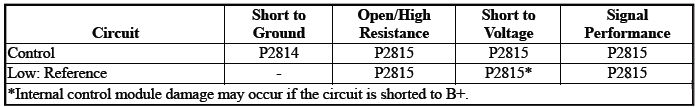
Typical Scan Tool Data
Pressure Control Solenoid Valve 7 Control Circuit Low Voltage Test Status
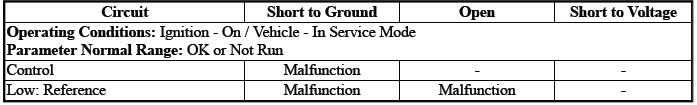
Pressure Control Solenoid Valve 7 Control Circuit Open Test Status
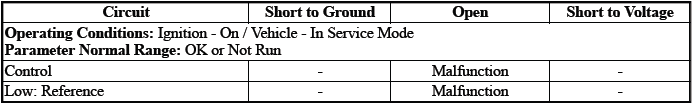
Pressure Control Solenoid Valve 7 High Voltage Test Status
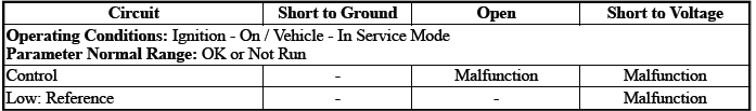
Circuit/System Description
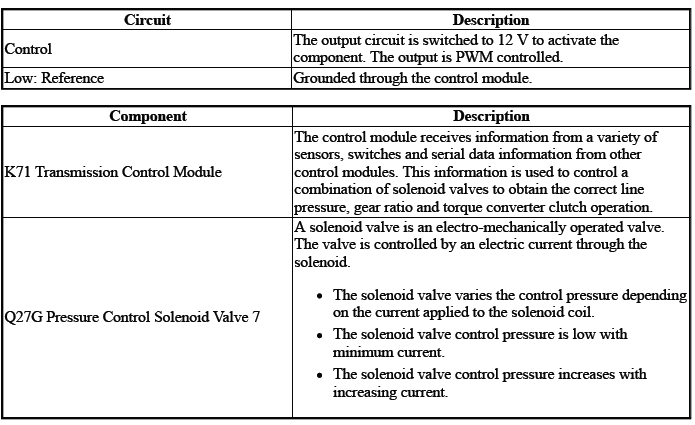
The solenoid valve controls the flow of transmission fluid to the hydraulic actuator that controls the C1 clutch. - During an autostart or autostop event
Conditions for Running the DTC
Ignition Voltage=9 to 32 V
DTCs run continuously when the above conditions are met for greater than 2 s.
Conditions for Setting the DTC
Control circuit=Commanded state does not match the actual state
Actions Taken When the DTC Sets
DTCs P2814, P2815 are Type B DTCs.
Autostart/Autostop=Disabled
Conditions for Clearing the DTC
DTCs P2814, P2815 are Type B DTCs.
Reference Information
Schematic: Reference
Refer to Automatic Transmission Controls Wiring Schematics
Connector End View: Reference
Refer to Component Connector End View Index
Component View: Reference
Refer to Disassembled Views
Description and Operation
Refer to Transmission General Description
Electrical Information: Reference
- Refer to Circuit Testing
- Refer to Connector Repairs
- Refer to Testing for Intermittent Conditions and Poor Connections
- Refer to Wiring Repairs
DTC Type: Reference
Refer to Powertrain Diagnostic Trouble Code (DTC) Type Definitions
Scan Tool: Reference
Refer to Control Module: References
Circuit/System Verification
1. Ignition - On / Vehicle - In Service Mode
2. Perform the scan tool control function:Auxiliary Transmission Fluid Pump - Enable & Disable
Verify the scan tool parameter:
- Pressure Control Solenoid Valve 7 High Voltage Test Status= OK or Not Run
- Pressure Control Solenoid Valve 7 Control Circuit Low Voltage Test Status= OK or Not Run
- Pressure Control Solenoid Valve 7 Control Circuit Open Test Status= OK or Not Run
- If not the specified state
Refer to Circuit/System Testing
- Go to next step: If the specified state
3. Perform the scan tool control function:Auxiliary Transmission Fluid Pump - Enable & Disable
Verify the component produces a clicking sound:Q27G Pressure Control Solenoid Valve 7
- If the component does not produce a sound
Refer to Circuit/System Testing
- Go to next step: If the component produces a sound
4. Operate the vehicle within the Conditions for Running the DTC. You may also operate the vehicle within the conditions that you observed from the Freeze Frame/Failure Records data.
5. Verify the DTC does not set.
- If the DTC sets
Refer to Circuit/System Testing
- Go to next step: If the DTC is not set
6. All OK.
Circuit/System Testing
NOTE: It may take up to 2 min for all vehicle systems to power down before an accurate ground or low reference circuit continuity test can be performed.
1. Ignition/Vehicle & All vehicle systems - Off
NOTE: Twisting or tilting of the transmission control module electrical connector while disconnecting may result in bent or misaligned electrical terminal pins.
2. Remove the component:K71 Transmission Control Module
NOTE: The component's temperature should be 19 to 21ºC (66 to 70ºF) while testing.
3. Test for 5.0 to 5.6 ohms between the test points:Control circuit terminal 30 & Low: Reference circuit terminal 29
- If not between 5.0 and 5.6 ohms
- Remove the component:Control Valve Body Cover
- Disconnect the electrical connector:Q27G Pressure Control Solenoid Valve 7
- Test for less than 2 ohms between the test points:
- Control circuit terminal 2@Component harness & Control circuit terminal 30@Control module harness
- Low: Reference circuit terminal 1@Component harness & Low: Reference circuit terminal 29@Control module harness
- If 2 ohms or greater - Replace the component:Automatic Transmission Wiring Harness
- If less than 2 ohms - Replace the component:Control Valve Body
- Go to next step: If between 5.0 and 5.6 ohms
4. Test for infinite resistance between the test points:
- Control circuit terminal 30 & Transmission Case
- Low: Reference circuit terminal 29 & Transmission Case
- If less than infinite resistance
- Remove the component:Control Valve Body Cover
- Disconnect the electrical connector:Q27A Pressure Control Solenoid Valve 1
- Test for infinite resistance between the test points:
- Control circuit terminal 2@Component harness & Transmission Case
- Low: Reference circuit terminal 1@Component harness & Transmission Case
- If less than infinite resistance - Replace the component:Automatic Transmission Wiring Harness
- If infinite resistance - Replace the component:Control Valve Body
- Go to next step: If infinite resistance
5. Test or replace the component:K71 Transmission Control Module
Component Testing
1. Ignition/Vehicle - Off
2. Disconnect the electrical connector:Q27G Pressure Control Solenoid Valve 7
NOTE: The component's temperature should be 19 to 21ºC (66 to 70ºF) while testing.
3. Test for 5.0 to 5.6 ohms between the test points:Control terminal 2 & Low: Reference terminal 1
- If not between 5.0 and 5.6 ohms
Replace the component:Control Valve Body
- Go to next step: If between 5.0 and 5.6 ohms
4. Test for infinite resistance between the test points:Each terminal of the component & The component's housing
- If less than infinite resistance
Replace the component:Control Valve Body
- Go to next step: If infinite resistance
5. All OK.
Repair Instructions
Perform the Diagnostic Repair Verification after completing the repair: Refer to Diagnostic Repair Verification
- Refer to Control Valve Body Replacement
- Refer to Wiring Harness Wire Replacement
- For control module replacement, programming, and setup: Refer to Control Module: References
Symptoms - Automatic Transmission
NOTE: Use the symptom tables only if the following conditions are met:
- Refer to Diagnostic Starting Point - Vehicle.
- There are no DTCs set.
- The control modules can communicate via the serial data link.
- Review the system operation in order to familiarize yourself with the system functions: Refer to Transmission General Description
Visual/Physical Inspection
Inspect the easily accessible or visible system components for obvious damage or conditions which could cause the symptom.
Intermittent
Faulty electrical connections or wiring may be the cause of intermittent conditions: Refer to Testing for Intermittent Conditions and Poor Connections.
Symptom List
Refer to a symptom diagnostic procedure from the following list in order to diagnose the symptom:
- Fluid Diagnosis
- Refer to Transmission Fluid Level and Condition Check
- Refer to Fluid Leak Diagnosis
- Noise and Vibration Diagnosis
- Refer to Noise and Vibration Analysis
- Refer to Torque Converter Diagnosis
- Shift Quality Feel Diagnosis
- Refer to Harsh Garage Shift
- Refer to Harsh Shifts
- Refer to Erratic Shift
- Refer to Slips in Drive or No Drive
- Shift Pattern
- Refer to No Upshift or Downshift
- Refer to No Manual Shift
- Torque Converter Diagnosis
- Refer to Torque Converter Diagnosis
- Symptom Not Found or No Symptom Detected
- Refer to Transmission Fluid Level and Condition Check
- Refer to Road Test
- Refer to Line Pressure Check
TRANSMISSION FLUID LEVEL AND CONDITION CHECK
Level Checking Procedure
1. Start the engine with the A/C turned off.
2. Move the shift lever to all positions from "P" to "D", waiting at least 2 seconds at each position. Repeat this again, and then return it to "P".
3. Raise and support the vehicle: Refer to Lifting and Jacking the Vehicle. The vehicle must be level, with the engine running and the shift lever in the PARK range.
NOTE:
- The vehicle must be level with the engine running and the shift lever in the PARK range.
- Use only recommended automatic transmission fluid: Refer to Adhesives, Fluids, Lubricants, and Sealers.
4. Wait until the automatic transmission fluid temperature reaches 35 - 45ºC (95 - 113ºF).
5.
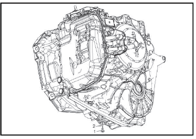
NOTE: Some residual automatic transmission fluid will drain from the level setting hole when the plug is initially removed.
Remove the transmission oil drain plug (1). Allow any fluid to drain.
1. Wait until the fluid first begins to flow as a steady stream and is within the specified temperature range, install the transmission oil drain plug (1).
2.
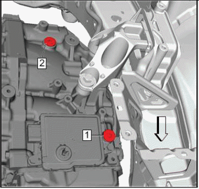
NOTE: The fluid filler plugs installed at locations 1 & 2 at the vehicle assembly plant are one-time-use. They have an interference fit and do not have O-rings.
Once removed, these plugs must be replaced. The service part (replacement plug) available in the GM Parts Catalog (EPC) comes with an O-ring. Lubricate the seal with AW-1 fluid and install the O-ring prior to installing the plug. At each subsequent service, the service part plug (replacement plug) O-ring seal must be replaced. It is a one-time-use part. It is available separate from the plug in the EPC.
If no fluid comes out and the temperature is within the specified range, add fluid until fluid drips out as a steady stream, and then install the transmission oil drain plug (1). Use only the recommended automatic transmission fluid: Refer to Adhesives, Fluids, Lubricants, and Sealers.
CAUTION: Refer to Fastener Caution.
6. Using a NEW transmission oil drain plug seal (2), install and tighten the transmission oil drain plug (1) to 8 N.m (6 lb ft).
Condition of Automatic Transmission Fluid
NOTE:
- Insufficient automatic transmission fluid level will cause the oil pump to draw in air, causing the line pressure to decrease. This causes the clutch to slip, resulting in malfunctions such as a burned clutch.
- Excessive/over filled automatic transmission fluid level will cause the gears in the automatic transmission to agitate the automatic transmission fluid, causing bubbling and malfunctions such as deterioration. If the vehicle is driven under this condition, the automatic transmission fluid level can increase and the automatic transmission fluid may blow out of the transmission breather vent hose.
- If the automatic transmission fluid contains an excessive amount of metal or friction material, internal wear of the automatic transmission is suspected.
1. Check that the automatic transmission fluid is free of foreign matter.
NOTE: If the automatic transmission fluid is cloudy, water contamination is suspected. Inspect the cooling system.
2. Check that the automatic transmission fluid is not discolored.
Line Pressure Check
Special Tools
- EN-21867 Pressure Gauge
- EN-21867-50 Transmission Line Pressure Adapter
For equivalent regional tools, refer to Special Tools.
Line Pressure

1. Apply the parking brake and chock the wheels.
2. Install an SLT current measuring machine.
If the machine is not available, installation is not required.
3.
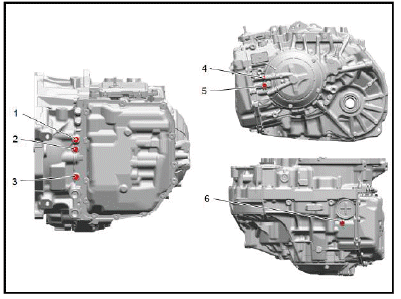
Disconnect the test plug (1) and install EN-21867 Pressure Gauge with EN-21867-50 adapter.
4. Start engine and shift to the "D" position then check oil pressure at idling engine speed.
5. Having completed steps 1 through 4, and with the brake pedal not depressed, line pressure at engine idle should fall within the range specified above.
6.
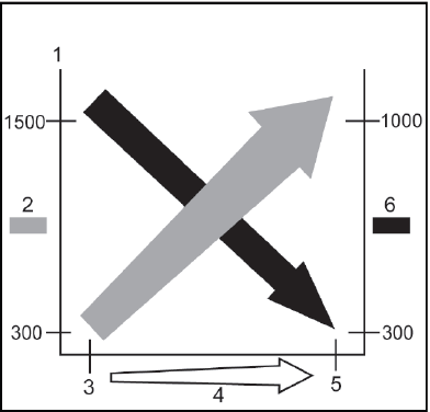
For the second portion of the line pressure check, firmly depress the brake pedal and perform three stall tests while monitoring the line pressure. Smoothly depress the accelerator pedal to progress from 0 to 100% for 5 seconds. Average the results of the 3 tests. Results should approximate values shown in the chart above.
- Drive Range
- Oil Pressure [kpa]
- Idle
- Throttle Opening
- Stall
- SLT current [mA]
NOTE:
- Stall testing causes a sudden rise in the automatic transmission fluid temperature (ATF). Do not continue each test for more than 5 seconds per test. Do not perform more than 3 times without allowing the transmission to cool.
- Line Pressure is actively controlled via the transmission control module (TCM). Some deviation from the chart above can be normal. It is important to perform the test 3 times and average the tests.
ROAD TEST
The purpose of the road test is to accurately grasp symptoms of the malfunction and to check completion after the repair is finished.
Be sure to perform the road test under the conditions below:
- Only when traffic conditions permit
- After engine inspection and adjustment.
- With ATF temperature 50-80ºC (122-176ºF) under ordinary driving conditions
- A/C, lights, etc., are turned OFF
- Cruise control is OFF
Perform the road test referring to the table below.
Road Test
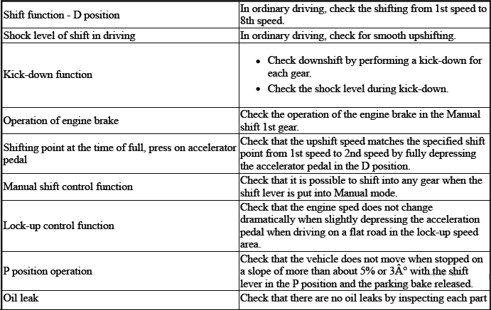
TORQUE CONVERTER DIAGNOSIS
The torque converter clutch (TCC) is applied by fluid pressure, which is controlled by a pulse width modulated (PWM) solenoid valve. This solenoid valve is located inside of the automatic transmission assembly. The solenoid valve is controlled through a combination of computer controlled switches and sensors.
Torque Converter Stator
The torque converter stator roller clutch can have two different malfunctions.
- The stator assembly freewheels in both directions.
- The stator assembly remains locked up at all times.
Poor Acceleration at Low Speed
If the stator is freewheeling at all times, the car tends to have poor acceleration from a standstill. At speeds above 50 - 55 km/h (30 - 35 mph), the car may act normally. For poor acceleration, you should first determine that the exhaust system is not blocked, and the transmission is in First gear when starting out.
If the engine freely accelerates to high RPM in NEUTRAL, you can assume that the engine and the exhaust system are normal. Check for poor performance in DRIVE and REVERSE to help determine if the stator is freewheeling at all times.
Poor Acceleration at High Speed
If the stator is locked up at all times, performance is normal when accelerating from a standstill. Engine RPM and car speed are limited or restricted at high speeds. Visual examination of the converter may reveal a blue color from overheating.
If the converter has been removed, you can check the stator roller clutch by inserting a finger into the splined inner race of the roller clutch and trying to turn the race in both directions. You should be able to freely turn the inner race clockwise, but you should have difficulty in moving the inner race counterclockwise or you may be unable to move the race at all.
Noise
NOTE: Do not confuse this noise with pump whine noise, which is usually noticeable in PARK, NEUTRAL and all other gear ranges. Pump whine will vary with line pressure.
You may notice a torque converter whine when the vehicle is stopped and the transmission is in DRIVE or REVERSE. This noise will increase as you increase the engine RPM. The noise will stop when the vehicle is moving or when you apply the torque converter clutch, because both halves of the converter are turning at the same speed.
Perform a stall test to make sure the noise is actually coming from the converter:
1. Place your foot on the brake.
2. Put the gear selector in DRIVE.
3. Depress the accelerator to approximately 1, 200 RPM for no more than 6 seconds.
CAUTION: You may damage the transmission if you depress the accelerator for more than 6 seconds.
A torque converter noise will increase under this load.
Torque Converter Clutch Shudder
The key to diagnosing TCC shudder is to note when it happens and under what conditions.
TCC shudder which is caused by the transmission should only occur during the apply or the release of the converter clutch. Shudder should never occur after the TCC plate is fully applied.
If the shudder occurs while the TCC is applying, the problem can be within the transmission or the torque converter.
Something is causing one of the following conditions to occur:
- Something is not allowing the clutch to become fully engaged.
- Something is not allowing the clutch to release.
- The clutch is releasing and applying at the same time.
One of the following conditions may be causing the problem to occur:
- Leaking turbine shaft seals
- A restricted release orifice
- A distorted clutch or housing surface due to long converter bolts
- Defective friction material on the TCC plate
If Shudder Occurs After TCC has Applied
If shudder occurs after the TCC has applied, most of the time there is nothing wrong with the transmission.
As mentioned above, the TCC is not likely to slip after the TCC has been applied. Engine problems may go unnoticed under light throttle and load, but they become noticeable after the TCC apply when going up a hill or accelerating. This is due to the mechanical coupling between the engine and the transmission.
Once TCC is applied, there is no torque converter, fluid coupling, assistance. Engine or driveline vibrations could be unnoticeable before TCC engagement.
Inspect the following components in order to avoid misdiagnosis of TCC shudder. An inspection will also avoid the unnecessary disassembly of a transmission or the unnecessary replacement of a torque converter.
- Spark plugs - Inspect for cracks, high resistance or a broken insulator.
- Coil - Look for a black discoloration on the bottom of the coil. This indicates arcing while the engine is misfiring.
- Fuel injector - The filter may be plugged.
- Vacuum leak - The engine will not get a correct amount of fuel. The mixture may run rich or lean depending on where the leak occurs.
- EGR valve (Petrol) - The valve may let in too much or too little unburnable exhaust gas and could cause the engine to run rich or lean.
- MAP sensor - Like a vacuum leak, the engine will not get the correct amount of fuel for proper engine operation.
- Carbon on the intake valves - Carbon restricts the proper flow of air/fuel mixture into the cylinders.
- Flat cam - Valves do not open enough to let the proper fuel/air mixture into the cylinders.
- Oxygen sensor - This sensor may command the engine too rich or too lean for too long.
- Fuel pressure - This may be too low.
- Engine mounts - Vibration of the mounts can be multiplied by TCC engagement.
- Axle joints - Check for vibration.
- TP Sensor (Petrol) - The TCC apply and release depends on the TP Sensor in many engines. If the TP Sensor is out of specification, TCC may remain applied during initial engine loading.
- Cylinder balance - Bad piston rings or poorly sealing valves can cause low power in a cylinder.
- Fuel contamination - This causes poor engine performance.
Torque Converter Evaluation and Diagnosis
Replace the torque converter if any of the following conditions exist:
- External leaks appear in the hub weld area.
- The converter hub is scored or damaged.
- The converter pilot is broken, damaged, or fits poorly into the crankshaft.
- You discover steel particles after flushing the cooler and the cooler lines.
- The pump is damaged, or you discover steel particles in the converter.
- The vehicle has TCC shudder and/or no TCC apply. Replace the torque converter only after all hydraulic and electrical diagnoses have been made. The converter clutch material may be glazed.
- The converter has an imbalance which cannot be corrected.
- The converter is contaminated with engine coolant which contains antifreeze.
- An internal failure occurs in the stator roller clutch.
- You notice excessive end play.
- Overheating produces heavy debris in the clutch.
- You discover steel particles or clutch lining material in the fluid filter or on the magnet, when no internal parts in the unit are worn or damaged. This condition indicates that lining material came from the converter.
Do not replace the torque converter if you discover any of the following symptoms:
- The oil has an odor or the oil is discolored, even though metal or clutch facing particles are not present.
- The threads in one or more of the converter bolt holds are damaged. Correct the condition with a new thread inset.
- Transmission failure did not display evidence of damaged or worn
internal parts, steel particles or clutch plate
lining material in the unit and inside the fluid filter.
- If the vehicle has been exposed to high mileage only. An exception may exist where the lining of the torque converter clutch dampener plate has seen excess wear by vehicles operated in heavy and/or constant traffic, such as taxi, delivery, or police use.
NOISE AND VIBRATION ANALYSIS
Idling
- Engine Malfunction
- Engine to Transmission Mounting
- Exhaust Pipe Resonance
- Drivetrain
- Suspension
- ATF Level/Condition
Garage Shift
- Engine Malfunction
- Engine to Transmission Mounting
- Exhaust Pipe Resonance
- Drivetrain
- Suspension
- Tire/Wheel Imbalance
- ATF Level/Condition
Driving
- Engine Malfunction
- Engine to Transmission Mounting
- Exhaust Pipe Resonance
- Drivetrain
- Suspension
- Tire/Wheel Imbalance
- ATF Level/Condition
Up Shift and/or Down Shift
- Engine Malfunction
- Engine to Transmission Mounting
- Exhaust Pipe Resonance
- Drivetrain
- Suspension
- ATF Level/Condition
ENGINE COOLANT/WATER IN TRANSMISSION
CAUTION: The antifreeze or water will deteriorate the seals, gaskets and the glue that bonds the clutch material to the pressure plate. Both conditions may cause damage to the transmission.
If antifreeze or water has entered the transmission, perform the following:
1. Replace all of the rubber type seals. The coolant will attack the seal material which will cause leakage.
2. Replace the torque converter.
3. Flush the cooler lines after the transmission cooler has been properly repaired or replaced.
Fluid Leak Diagnosis
General Method
1. Verify that the leak is transmission fluid.
2. Thoroughly clean the suspected leak area.
3. Operate the vehicle for 24 km (15 mi), or until normal operating temperatures are reached.
4. Park the vehicle over clean paper or cardboard.
5. Shut OFF the engine.
6. Look for fluid spots on the paper.
7. Make the necessary repairs.
Powder Method
1. Thoroughly clean the suspected leak area with solvent.
2. Apply an aerosol type leak tracing powder to the suspected leak area.
3. Operate the vehicle for 24 km (15 mi), or until normal operating temperatures are reached.
4. Shut OFF the engine.
5. Inspect the suspected leak area.
6. Trace the leak path through the powder in order to find the source of the leak.
7. Make the necessary repairs.
Dye and Black Light Method
A fluid dye and black light kit is available from various tool manufacturers.
1. Follow the manufacturer instructions in order to determine the amount of dye to use.
2. Operate the vehicle for 24 km (15 mi) or until normal operating temperatures are reached.
3. Detect the leak with the black light.
4. Make the necessary repairs.
Find the Cause of the Leak
Pinpoint the leak and trace the leak back to the source. You must determine the cause of the leak in order to repair the leak properly. For example, if you replace a gasket, but the sealing flange is bent, the new gasket will not repair the leak. You must also repair the bent flange. Before you attempt to repair a leak, check for the following conditions, and make repairs as necessary:
Gaskets
- Fluid level/pressure is too high.
- Plugged vent or drain-back holes.
- Improperly tightened fasteners.
- Dirty or damaged threads.
- Warped flanges or sealing surface.
- Scratches, burrs, or other damage to the sealing surface.
- Damaged or worn gasket.
- Cracking or porosity of the component.
- Improper sealant used, where applicable.
- Incorrect gasket.
Seals
- Fluid level/pressure is too high.
- Plugged vent or drain-back holes.
- Damaged or worn seal.
- Cracks in component.
- Manual shaft or output shaft surface is scratched, nicked, or damaged.
- Loose or worn bearing causing excess seal wear.
Possible Points of Fluid Leaks
Transmission Valve Body Cover
- Incorrectly tightened bolts.
- Improperly installed or damaged gasket/seal.
- Damaged mounting face.
- Incorrect gasket seal.
Transmission Case Leak
- Loose or damaged oil cooler lines/seals.
- Worn or damaged axle shaft oil seal.
- Loose line pressure pipe plug or fluid level pipe plug.
Leak at the Transmission Vent
- Overfilled system.
- Water or coolant in the fluid. The fluid will appear milky. Check vent hose mounting.
- Plugged vent.
Harsh Garage Shift
"N" to "D"
- ATF Level/Condition
- TCM
- Shift Cable Adjustment
- Valve Body
"N" to "R"
- ATF Level/Condition
- TCM
- Shift Cable Adjustment
- Valve Body
ERRATIC SHIFT
Erratic Shifting
- Output Speed Sensor (NOUT)
- TCM
SLIPS IN DRIVE OR NO DRIVE
No Move or Slip in "D"
- ATF Level/Condition
- TCM
- Shift Cable Adjustment
- Torque Converter
- Valve Body
- Forward Clutch Pressure Control Solenoid (Gears 1-2-3-4-5) (SL1)
No Move or Slip in "R"
- ATF Level/Condition
- Shift Solenoid 1 (S1)
- Shift Solenoid 2 (S2)
- 3rd Clutch Pressure Control Solenoid (Gears 3-7-R) (SL3)
- TCM
- Shift Cable Adjustment
- Torque Converter
- Valve Body
Slip On Acceleration
- ATF Level/Condition
- Engine Malfunction
- Line Pressure Control Solenoid (SLT)
- TCM
- Shift Cable Adjustment
- Torque Converter
- Valve Body
NO UPSHIFT OR DOWNSHIFT
1st to 2nd or 2nd to 1st
- ATF Level/Condition
- Valve Body
- TCM
- Engine Malfunction
- Battery Voltage Low
- Output Speed Sensor (NOUT)
- Input Speed Sensor (NIN)
- Oil Temperature Sensor (OT)
- Shift Solenoid 1 (S1)
- 3rd Clutch Pressure Control Solenoid (Gears 4-6) (SL4)
2nd to 3rd or 3rd to 2nd
- ATF Level/Condition
- Valve Body
- TCM
- Engine Malfunction
- Battery Voltage Low
- Output Speed Sensor (NOUT)
- Input Speed Sensor (NIN)
- Oil Temperature Sensor (OT)
- Shift Solenoid 1 (S1)
- 3rd Clutch Pressure Control Solenoid (Gears 3-7-R) (SL3)
- 3rd Clutch Pressure Control Solenoid (Gears 4-6) (SL4)
3rd to 4th or 4th to 3rd
- ATF Level/Condition
- Valve Body
- TCM
- Engine Malfunction
- Battery Voltage Low
- Output Speed Sensor (NOUT)
- Input Speed Sensor (NIN)
- Oil Temperature Sensor (OT)
- Shift Solenoid 1 (S1)
- Direct Clutch Pressure Control Solenoid (Gears 5-6-7-8) (SL2)
- 3rd Clutch Pressure Control Solenoid (Gears 3-7-R) (SL3)
- 3rd Clutch Pressure Control Solenoid (Gears 4-6) (SL4)
- Shift Solenoid 2 (S2)
4th to 5th or 5th to 4th
- ATF Level/Condition
- Valve Body
- TCM
- Engine Malfunction
- Battery Voltage Low
- Output Speed Sensor (NOUT)
- Input Speed Sensor (NIN)
- Oil Temperature Sensor (OT)
- Forward Clutch Pressure Control Solenoid (SL1)
- 3rd Clutch Pressure Control Solenoid (Gears 3-7-R) (SL3)
- 3rd Clutch Pressure Control Solenoid (Gears 4-6) (SL4)
5th to 6th or 6th to 5th
- ATF Level/Condition
- Valve Body
- TCM
- Engine Malfunction
- Battery Voltage Low
- Output Speed Sensor (NOUT)
- Input Speed Sensor (NIN)
- Oil Temperature Sensor (OT)
- Forward Clutch Pressure Control Solenoid (SL1)
- 3rd Clutch Pressure Control Solenoid (Gears 3-7-R) (SL3)
- 3rd Clutch Pressure Control Solenoid (Gears 4-6) (SL4)
6th to 7th or 7th to 6th
- ATF Level/Condition
- Valve Body
- TCM
- Engine Malfunction
- Battery Voltage Low
- Output Speed Sensor (NOUT)
- Input Speed Sensor (NIN)
- Oil Temperature Sensor (OT)
- Forward Clutch Pressure Control Solenoid (SL1)
- 3rd Clutch Pressure Control Solenoid (Gears 3-7-R) (SL3)
- 3rd Clutch Pressure Control Solenoid (Gears 4-6) (SL4)
7th to 8th or 8th to 7th
- ATF Level/Condition
- Valve Body
- TCM
- Engine Malfunction
- Battery Voltage Low
- Output Speed Sensor (NOUT)
- Input Speed Sensor (NIN)
- Oil Temperature Sensor (OT)
- Forward Clutch Pressure Control Solenoid (SL1)
- 3rd Clutch Pressure Control Solenoid (Gears 3-7-R) (SL3)
- Direct Clutch Pressure Control Solenoid (Gears 5-6-7-8) (SL2)
- Forward Band Solenoid (Gears 2-8) (SL5)
No Torque Converter Lock-up ON or OFF
- ATF Level/Condition
- Valve Body
- TCM
- Torque Converter Lock-up Control Solenoid (SLU)
- Battery Voltage Low
- Output Speed Sensor (NOUT)
- Input Speed Sensor (NIN)
- Oil Temperature Sensor (OT)
No 1st Gear Engine Braking
- Fluid Level Low
- Valve Body
- TCM
- Shift Solenoid 1 (S1)
- Shift Solenoid 2 (S2)
- Battery Voltage Low
No Kickdown
- TCM
NO MANUAL SHIFT
No Manual Shifting
- TCM
NO ENGINE START
No Engine Start
- Engine Malfunction
- Battery Voltage Low
- TCM
- Shift Cable Adjustment
ENGINE STALLS WHEN SHIFTING FROM NEUTRAL TO DRIVE OR REVERSE
"N" to "D"
- Engine Malfunction
- Torque Converter Lock-up Control Solenoid (SLU)
- TCM
- Torque Converter
- Valve Body
"N" to "R"
- Engine Malfunction
- Torque Converter Lock-up Control Solenoid (SLU)
- TCM
- Torque Converter
- Valve Body
Deceleration
- Engine Malfunction
- Torque Converter Lock-up Control Solenoid (SLU)
- TCM
- Torque Converter
- Valve Body
HARSH SHIFTS
"N" to "D"
- Battery Voltage Low
- Oil Temperature Sensor (OT)
- Forward Clutch Pressure Control Solenoid (Gears 1-2-3-4-5) (SL1)
- 3rd Clutch Pressure Control Solenoid (Gears 4-6) (SL4)
- TCM
- ATF Level/Condition
- Valve Body
"N" to "R"
- Battery Voltage Low
- Oil Temperature Sensor (OT)
- 3rd Clutch Pressure Control Solenoid (Gears 3-7-R) (SL3)
- 3rd Clutch Pressure Control Solenoid (Gears 4-6) (SL4)
- TCM
- ATF Level/Condition
- Valve Body
Up-Shift
- Battery Voltage Low
- Oil Temperature Sensor (OT)
- Forward Clutch Pressure Control Solenoid (Gears 1-2-3-4-5) (SL1)
- Direct Clutch Pressure Control Solenoid (Gears 5-6-7-8) (SL2)
- 3rd Clutch Pressure Control Solenoid (Gears 3-7-R) (SL3)
- 3rd Clutch Pressure Control Solenoid (Gears 4-6) (SL4)
- TCM
- ATF Level/Condition
- Valve Body
Down-Shift
- Battery Voltage Low
- Oil Temperature Sensor (OT)
- Line Pressure Control Solenoid (SLT)
- Forward Clutch Pressure Control Solenoid (Gears 1-2-3-4-5) (SL1)
- Direct Clutch Pressure Control Solenoid (Gears 5-6-7-8) (SL2)
- 3rd Clutch Pressure Control Solenoid (Gears 3-7-R) (SL3)
- 3rd Clutch Pressure Control Solenoid (Gears 4-6) (SL4)
- TCM
- ATF Level/Condition
- Valve Body
Kick Down
- Battery Voltage Low
- Oil Temperature Sensor (OT)
- Forward Clutch Pressure Control Solenoid (Gears 1-2-3-4-5) (SL1)
- Direct Clutch Pressure Control Solenoid (Gears 5-6-7-8) (SL2)
- 3rd Clutch Pressure Control Solenoid (Gears 3-7-R) (SL3)
- 3rd Clutch Pressure Control Solenoid (Gears 4-6) (SL4)
- TCM
- ATF Level/Condition
- Valve Body
READ NEXT:
 Repair Instructions - On Vehicle
Gear Selector -N- Position Learn
Diagnostic Instructions
Perform the Diagnostic System Check prior to using this diagnostic
procedure: Refer to Diagnostic System
Check - Vehicle
Review the descr
Repair Instructions - Off Vehicle
Torque Converter Assembly Removal
Torque Converter
TORQUE CONVERTER FLUID SEAL REMOVAL
Torque Converter Fluid Seal
Special Tools
EN-45000 Seal Remover
Equivalent regional tools: Refer to S
Description and Operation
Transmission Identification Information
For automatic transmission AF50, the identification plate is on the top of
the transmission housing.
Aisin Warner transmission type
Fabrication line 1 = 00
SEE MORE:
Description and Operation
POWER STEERING SYSTEM DESCRIPTION AND OPERATION (ELECTRONIC POWER
STEERING)
K43 - K43 Power Steering Control Module
K17 - K17 Electronic Brake Control Module
P16 - P16 Instrument Cluster
B137 - B137 Power Steering Shaft Torque Sensor
M38 - M38 Power Steering Motor
The power steering system consists
Description and Operation
AUTOMATIC HVAC DESCRIPTION AND OPERATION
The air temperature and the air delivery description and operation are
divided into eight areas:
HVAC Control Components
Air Speed
Air Delivery
Heating and A/C Operation
Recirculation Operation
Automatic Operation
Engine Coolant and A/C System Refrig
