Opel Insignia: Repair Instructions - On Vehicle
Gear Selector -N- Position Learn
Diagnostic Instructions
- Perform the Diagnostic System Check prior to using this diagnostic procedure: Refer to Diagnostic System Check - Vehicle
- Review the description of Strategy Based Diagnosis: Refer to Strategy Based Diagnosis
Description
- For an overview of the component/system, refer to Electronic Component Description
- This procedure triggers the control module to learn the values of the component:
When to Perform the Procedure
NOTE: Failure to perform this procedure may result in poor system performance, DTCs being set, or customer dissatisfaction.
This procedure is required when the following component has been repaired, replaced, removed, or serviced:
- K71 Transmission Control Module
- T12 Automatic Transmission Assembly
Conditions for Running the Procedure
- Transmission Range=Neutral
- Park Brake=Applied
- Drive Wheels=Blocked
Reference Information
Scan Tool: Reference
Refer to Control Module: References
With Scan Tool
1. Ignition - On / Vehicle - In Service Mode.
2. Select:Module Diagnostics.
3. Select:Transmission Control Module.
4. Select:Configuration/Reset Functions.
5. Select:Gear Selector -N- Position Learn.
6. Follow the instructions on the scan tool.
7. All OK.
Repair Instructions
Perform the Diagnostic Repair Verification after completing the repair: Refer to Diagnostic Repair Verification
For control module replacement, programming, and setup: Refer to Control Module: References
LEARNED VALUES RESET
Diagnostic Instructions
- Perform the Diagnostic System Check prior to using this diagnostic procedure: Refer to Diagnostic System Check - Vehicle
- Review the description of Strategy Based Diagnosis:Strategy Based Diagnosis
Description
For an overview of the component/system, refer to Electronic Component Description
This procedure resets the control module learned values of the component/system:K71 Transmission Control Module
When to Perform the Procedure
NOTE: Failure to perform this procedure may result in poor system performance, DTCs being set, or customer dissatisfaction.
This procedure is required when the following component has been repaired, replaced, removed, or serviced:
- K71 Transmission Control Module
- T12 Automatic Transmission Assembly
Conditions for Running the Procedure
Transmission Fluid Temperature=50 to 80ºC (122 to 176ºF)
Reference Information
Scan Tool: Reference
Refer to Control Module: References
With Scan Tool
1. Ignition - On / Vehicle - In Service Mode.
2. Select:Module Diagnostics.
3. Select:Transmission Control Module.
4. Select:Configuration/Reset Functions.
5. Select:Learned Values Reset.
6. Follow the instructions on the scan tool.
7. Perform the following steps:
- Engine=Running
- Move the selector lever from N to D and wait 5 s in each range. Then move the selector lever back to N.
- Move the selector lever from N to R and wait 5 s in each range. Then move the selector lever back to N.
NOTE: Step 5, 6, 7 requires the vehicle to be driven on the road. Do NOT use manual mode function to perform the following steps:
- Transmission=Drive
- From a stop, accelerate to 72 km/h (45 MPH) with the throttle position between 15 and 25%.
- From a stop, accelerate to 72 km/h (45 MPH) with the throttle position between 45 and 55%.
- From a stop, accelerate to 72 km/h (45 MPH) with the throttle position greater than 70%.
- Ignition=Off - For greater than 2 min
- From a stop, accelerate until the transmission reaches gear 8 and then coast down to a stop. - More than 10 times.
8. All OK.
Repair Instructions
Perform the Diagnostic Repair Verification after completing the repair: Refer to Diagnostic Repair Verification
For control module replacement, programming, and setup: Refer to Control Module: References
Connector Reconnection - Automatic Transmission
Special Tools
EL-35616 Terminal Test Probe Kit
For equivalent regional tools, refer to Special Tools.
When the condition is not currently present, but is indicated in DTC history, the cause may be intermittent. An intermittent may also be the cause when there is a customer complaint, but the symptom cannot be duplicated: Refer to the Symptom Table of the system that is suspect of causing the condition before trying to locate an intermittent condition.
Most intermittent conditions are caused by faulty electrical connections or wiring. Inspect for the following items:
- Loose, corroded, or painted terminal stud/fastener
- Wiring broken inside the insulation
- Poor connection between the male and female terminal at a connector
- A terminal not seated all the way into the connector body
- Poor terminal to wire connection - Some conditions which fall under this description are poor crimps, poor solder joints, crimping over the wire insulation rather than the wire itself, and corrosion in the wire to terminal contact area, etc.
- Pierced or damaged insulation can allow moisture to enter the wiring causing corrosion. The conductor can corrode inside the insulation, with little visible evidence. Look for swollen and stiff sections of wire in the suspect circuits.
- Wiring which has been pinched, cut, or its insulation rubbed through may cause an intermittent open or short as the bare area touches other wiring or parts of the vehicle.
- Wiring that comes in contact with hot or exhaust components
- Refer to Inducing Intermittent Fault Conditions in order to duplicate the conditions required, in order to verify the customer concern.
- Refer to Testing for Electrical Intermittents for test procedures to detect intermittent open, high resistance, short to ground, and short to voltage conditions.
- Refer to Scan Tool Snapshot Procedure for advanced intermittent diagnosis and Vehicle Data Recorder operation.
Testing for Terminal Fretting
Some intermittent conditions can be caused by wire terminal fretting corrosion. Fretting corrosion is a build-up of insulating, oxidized wear debris that can form when there is a small motion between electrical contacts. The oxidized wear debris can pile up enough at the electrical contact spots that the electrical resistance across the connection increases. Movement between the contacting surfaces as small as 10 to 100 microns can cause fretting.
To put this in perspective, a sheet of paper is about 100 microns thick, so fretting motion is small and hard to see.
Vibration and thermal expansion/contraction are the main sources that create fretting motion. Since vehicles vibrate and can experience large temperature swings, they are a good source for fretting motion. Tin, copper, nickel, and iron surfaces are all susceptible to fretting corrosion. Fretting corrosion can be difficult to see but it looks like small, dark smudges on the terminals contact surface.
To correct a fretting condition disconnect the suspect connector and add dielectric grease / lubricant (Nyogel 760G or equivalent, meeting GM specification 9986087) to both sides of the connector terminals. Then reconnect the connector and wipe away any excess lubricant. This will correct the additional terminal contact resistance due to the terminal fretting corrosion.
Testing for Proper Terminal Contact
It is important to test terminal contact at the component and any inline connectors before replacing a suspect component. Mating terminals must be inspected to ensure good terminal contact. A poor connection between the male and female terminal at a connector may be the result of contamination or deformation.
Contamination may be caused by the connector halves being improperly connected. A missing or damaged connector seal, damage to the connector itself, or exposing the terminals to moisture and dirt can also cause contamination. Contamination, usually in the underhood or underbody connectors, leads to terminal corrosion, causing an open circuit or intermittently open circuit.
Deformation is caused by probing the mating side of a connector terminal without the proper adapter. Always use the EL-35616 kit when probing connectors. Other causes of terminal deformation are improperly joining the connector halves, or repeatedly separating and joining the connector halves. Deformation, usually to the female terminal contact tang, can result in poor terminal contact causing an open or intermittently open circuit.
Testing for Proper Terminal Contact in Bussed Electrical Centers
It is very important to use the correct test adapter when testing for proper terminal contact of fuses and relays in a bussed electrical center. Use the EL-35616 kit to test for proper terminal contact. Failure to use the EL-35616 kit can result in improper diagnosis of the bussed electrical center.
Follow the procedure below in order to test terminal contact:
1. Separate the connector halves.
2. Visually inspect the connector halves for contamination. Contamination may result in a white or green buildup within the connector body or between terminals. This causes high terminal resistance, intermittent contact, or an open circuit. An underhood or underbody connector that shows signs of contamination should be replaced in its entirety: terminals, seals, and connector body.
3. Using an equivalent male terminal/terminated lead, verify that the retention force is significantly different between a known good terminal and the suspect terminal. Replace the female terminal in question.
Flat Wire Connectors
There are no serviceable parts for flat wire connectors on the harness side or the component side.
Follow the procedure below in order to test terminal contact:
1. Remove the component in question.
2. Visually inspect each side of the connector for signs of contamination. Avoid touching either side of the connector as oil from your skin may be a source of contamination as well.
3. Visually inspect the terminal bearing surfaces of the flat wire circuits for splits, cracks, or other imperfections that could cause poor terminal contact. Visually inspect the component side connector to ensure that all of the terminals are uniform and free of damage or deformation.
4. Insert the appropriate adapter into the flat wire harness connector in order to test the circuit in question.
Control Module/Component Voltage and Grounds
Poor voltage or ground connections can cause widely varying symptoms.
- Test all control module voltage supply circuits. Many vehicles have multiple circuits supplying voltage to a control module. Other components in the system may have separate voltage supply circuits that may also need to be tested. Inspect connections at the module/component connectors, fuses, and any intermediate connections between the voltage source and the module/component. A test lamp or a DMM may indicate that voltage is present, but neither tests the ability of the circuit to carry sufficient current. Operate the component to test the ability of the circuit to carry sufficient current: Refer to Circuit Testing and Power Distribution Wiring Schematics.
- Test all control module ground and system ground circuits. The control module may have multiple ground circuits. Other components in the system may have separate grounds that may also need to be tested. Inspect grounds for clean and tight connections at the grounding point (screw or stud). Inspect the connections at the component and in splice packs, where applicable. Operate the component to test the ability of the circuit to carry sufficient current: Refer to Circuit Testing and Ground Distribution Wiring Schematics.
Temperature Sensitivity
- An intermittent condition may occur when a component/connection reaches
normal operating temperature.
The condition may occur only when the component/connection is cold, or only when the component/connection is hot.
- Freeze Frame, Failure Records, Snapshot, or Vehicle Data Recorder data may help with this type of intermittent condition, where applicable.
- If the intermittent is related to heat, review the data for a
relationship with the following:
- High ambient temperatures
- Underhood/engine generated heat
- Circuit generated heat due to a poor connection, or high electrical load
- Higher than normal load conditions, towing, etc.
- If the intermittent is related to cold, review the data for the
following:
- Low ambient temperatures - In extremely low temperatures, ice may form in a connection or component. Inspect for water intrusion.
- The condition only occurs on a cold start.
- The condition goes away when the vehicle warms up.
- Information from the customer may help to determine if the trouble follows a pattern that is temperature related.
- If temperature is suspected of causing an intermittent fault condition, attempt to duplicate the condition: Refer to Inducing Intermittent Fault Conditions in order to duplicate the conditions required.
Electromagnetic Interference and Electrical Noise
Some electrical components/circuits are sensitive to electromagnetic interference or other types of electrical noise.
Inspect for the following conditions:
- A mis-routed harness that is too close to high voltage/high current devices such as secondary ignition components, motors, generator etc. - These components may induce electrical noise on a circuit that could interfere with normal circuit operation.
- Electrical system interference caused by a malfunctioning relay, or a control module driven solenoid or switch - These conditions can cause a sharp electrical surge. Normally, the condition will occur when the malfunctioning component is operating.
- Installation of non-factory or aftermarket add on accessories such as lights, 2-way radios, amplifiers, electric motors, remote starters, alarm systems, cell phones, etc. - These accessories may create interference in other circuits while operating and the interference would disappear when the accessory is not operating: Refer to Checking Aftermarket Accessories.
- Test for an open diode across the A/C compressor clutch and for other open diodes. Some relays may contain a clamping diode.
- The generator may be allowing AC noise into the electrical system.
Incorrect Control Module
- There are only a few situations where reprogramming a control module is
appropriate:
- A new service control module is installed.
- A control module from another vehicle is installed.
- Revised software/calibration files have been released for this vehicle.
NOTE: DO NOT re-program the control module with the SAME software/calibration files that are already present in the control module. This is not an effective repair for any type of concern.
- Verify that the control module contains the correct software/calibration. If incorrect programming is found, reprogram the control module with the most current software/calibration: Refer to Control Module: References for replacement, setup, and programming.
Range Selector Lever Cable Replacement
Removal Procedure
1. Battery Tray - Remove - Refer to Battery Tray Replacement.
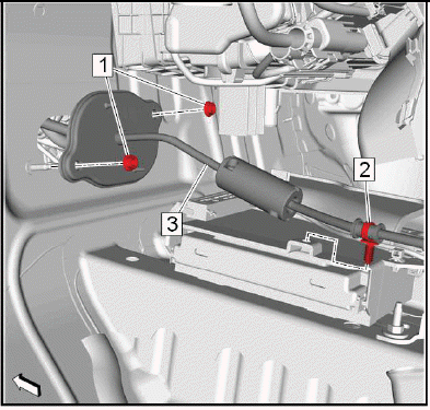
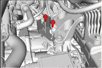
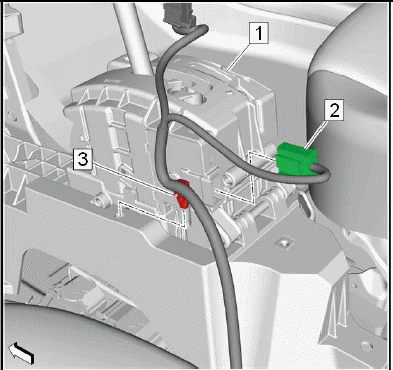
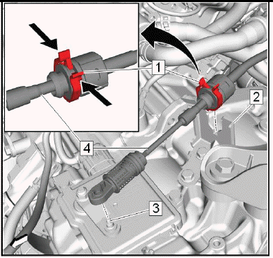
2.
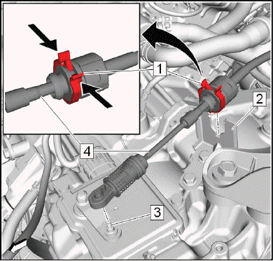
Range Selector Lever Cable (4) @Range Selector Lever Cable Lever (3) - Remove.
3. Range Selector Lever Cable@Transmission Range Selector Lever Cable Bracket (2) - Remove.
- Push (arrows) the 2 latches of the retainer (1) to release the range selector lever cable from the bracket.
4. Transmission Control Lever Knob - Remove - Refer to Transmission Control Lever Knob Replacement.
5. Front Floor Console - Remove - Refer to Front Floor Console Replacement.
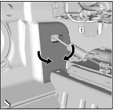
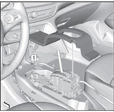
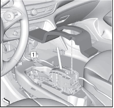
6.
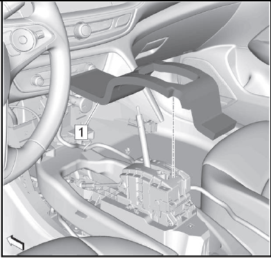
Transmission Control Lever Insulator (1) - Remove.
7. Front Floor Console Rear Air Front Duct - Remove - Refer to Front Floor Console Rear Air Duct Replacement (Front) Refer to Front Floor Console Rear Air Duct Replacement (Rear).
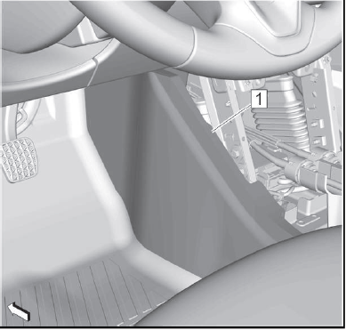
8.
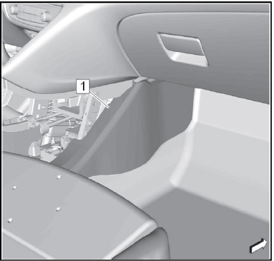
Front Floor Panel Carpet-Right Side (1) - Position aside.
9.
Air Conditioning Evaporator and Blower Module Drain Hose (1) @Air Conditioning Evaporator and Blower Case (2) - Disconnect.
10. Air Conditioning Evaporator and Blower Module Drain Hose - Position aside.
11. Accelerator Pedal Position Sensor - Remove - Refer to Accelerator Pedal with Position Sensor Assembly Replacement.
12.
Front Floor Panel Carpet-Left Side (1) - Position aside.
13.
Floor Rear Air Outlet Duct Adapter-Left Side (1) - Remove.
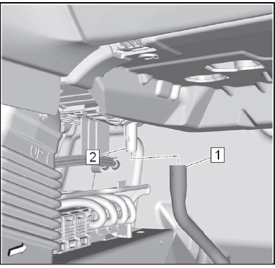
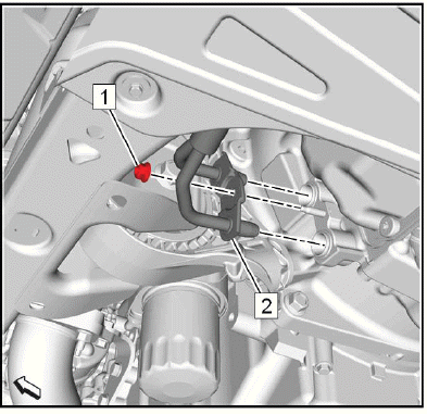
14.

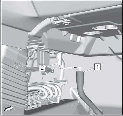
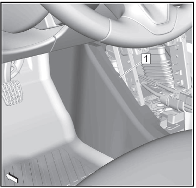
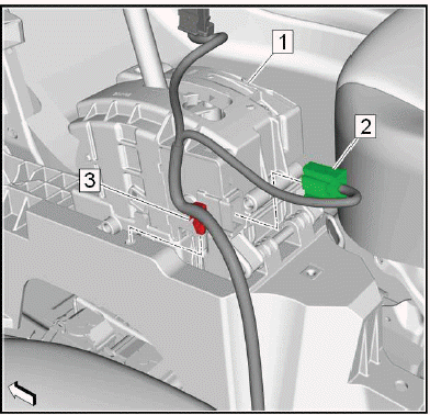
Range Selector Lever Cable (1) @Transmission Control (2) - Remove.
- Remove the range selector lever cable with a suitable tool from the ball joint of the transmission control.
- Push (arrows) the 2 latches of the retainer (3) to release the range selector lever cable from the front of the transmission control.
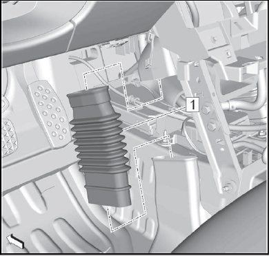
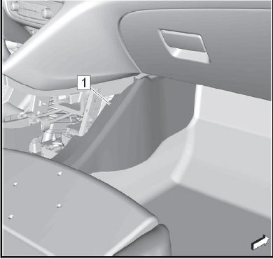
15.
Dash Panel Inner Insulator (1) - Position aside.
- Flap (arrows) the dash panel inner insulator aside, to gain access to the transmission range selector lever cable grommet nuts.
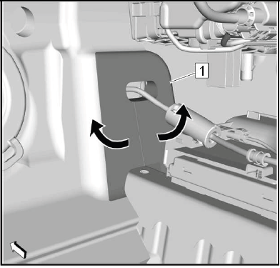
16.
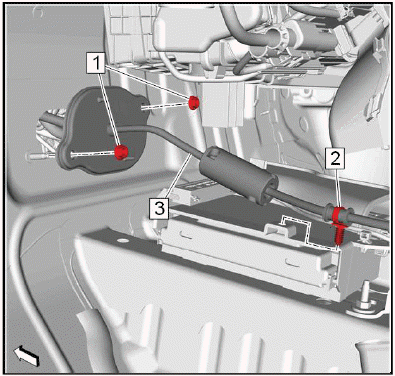
Range Selector Lever Cable Retainer (2) @Body Control Module Bracket - Unclip.
17. Transmission Range Selector Lever Cable Grommet Nut (1) - Remove[2x].
18. Range Selector Lever Cable (3) @Vehicle - Remove.
Installation Procedure
1.
Range Selector Lever Cable (3) @Vehicle - Install.
2. Transmission Range Selector Lever Cable Grommet Nut (1) - Install and tighten[2x]6.5N.m (58 lb in).
3. Range Selector Lever Cable Retainer (2) @Body Control Module Bracket - Install.
4.
Dash Panel Inner Insulator (1) - Reposition.
5.
Range Selector Lever Cable (1) @Transmission Control (2) - Install.
- Push the range selector lever cable to the front of the transmission control. The retainer (3) must engage noticeable.
- Install the range selector lever cable to the ball joint of the transmission control.
6.

Floor Rear Air Outlet Duct Adapter-Left Side (1) - Install.
7.
Front Floor Panel Carpet-Left Side (1) - Reposition.
8. Accelerator Pedal Position Sensor - Install - Refer to Accelerator Pedal with Position Sensor Assembly Replacement.
9.
Air Conditioning Evaporator and Blower Module Drain Hose (1) @Air Conditioning Evaporator and Blower Case (2) - Connect.
10.
Front Floor Panel Carpet-Right Side (1) - Reposition.
11. Front Floor Console Rear Air Front Duct - Install - Refer to Front Floor Console Rear Air Duct Replacement (Front) Refer to Front Floor Console Rear Air Duct Replacement (Rear).
12.
Transmission Control Lever Insulator (1) - Install.
13. Front Floor Console - Install - Refer to Front Floor Console Replacement.
14. Transmission Control Lever Knob - Install - Refer to Transmission Control Lever Knob Replacement.
15.
Range Selector Lever Cable (4) @Transmission Range Selector Lever Cable Bracket (2) - Install.
- Push the range selector lever cable into the bracket. The retainer (1) must engage noticeable.
16. Range Selector Lever Cable@Range Selector Lever Cable Lever (3) - Install.
17. Range Selector Lever Cable - Adjust - Refer to Range Selector Lever Cable Adjustment.
18. Battery Tray - Install - Refer to Battery Tray Replacement.
Range Selector Lever Cable Adjustment
Removal Procedure
1. Battery Tray - Remove - Refer to Battery Tray Replacement.
Adjustment Procedure
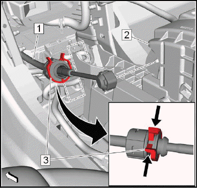
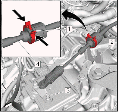
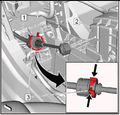
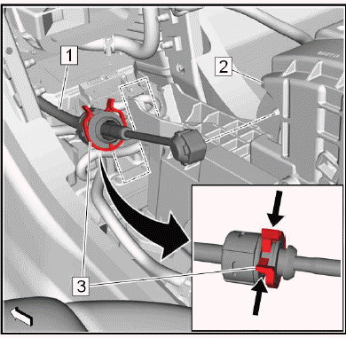
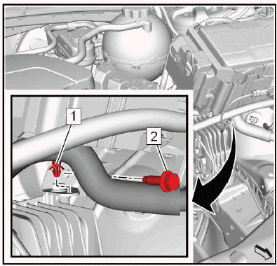
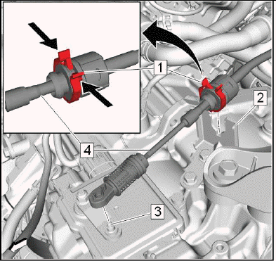
1.
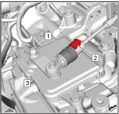
Push the secure ring (1) against the spring force forwards.
2. Lift the range selector lever cable retainer (2) in order to remove the mechanical connection between transmission control and transmission.
3. Ensure that the range selector lever cable lever (3) is in position "P".
4.
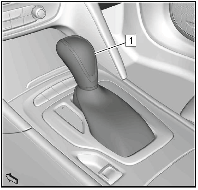
Ensure that the transmission control lever (1) is in position "P".
5.
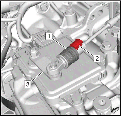
Push the secure ring (1) against the spring force forwards.
6. Install the range selector lever cable retainer (2) in order to install the mechanical connection between the transmission control and the transmission.
7. The secure ring must flip backwards and secure the range selector lever cable retainer.
Installation Procedure
1. Battery Tray - Install - Refer to Battery Tray Replacement.
RANGE SELECTOR LEVER CABLE BRACKET REPLACEMENT
Preliminary Procedures
1. Refer to Battery Tray Replacement.
2. Range Selector Lever Cable@Range Selector Lever Cable Lever & Transmission Range Selector Lever Cable Bracket - Remove - Refer to Range Selector Lever Cable Replacement.
- Transmission Range Selector Lever Cable Bracket Bolt[2x]
CAUTION: Refer to Fastener Caution
Tighten 22N.m (16 lb ft)
- Transmission Range Selector Lever Cable Bracket
Procedure
Refer to Range Selector Lever Cable Adjustment
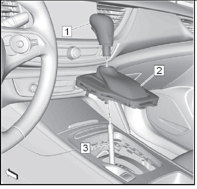
Transmission Control Lever Knob Replacement
Removal Procedure
1. Set the parking brake.
2. Shift the transmission control lever into Reverse position.
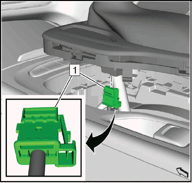
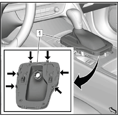
3.
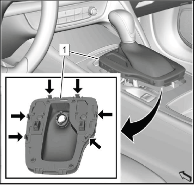
Gently release the transmission control lever boot bezel (1) at the front. Unclip 6 retainers (arrows), using a flat bladed tool.
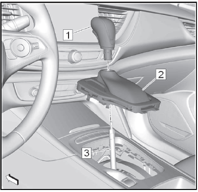
4. Pull the transmission control lever boot bezel up to gain access to the electrical connector.
5.
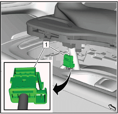
Electrical Connector (1) - Disconnect.
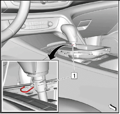
6.
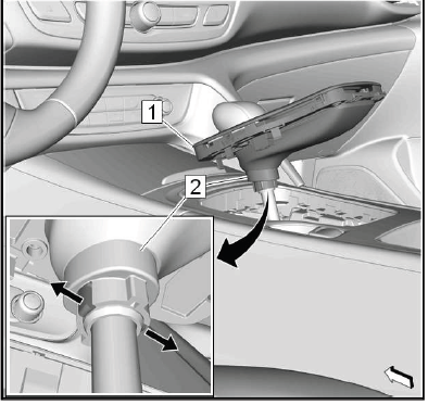
Pull the transmission control lever boot bezel (1) up to gain access to the transmission control lever boot retaining ring (2).
7. Release (arrows) the 2 latches of the transmission control lever boot retaining ring to separate the transmission control lever boot from the transmission control lever knob.
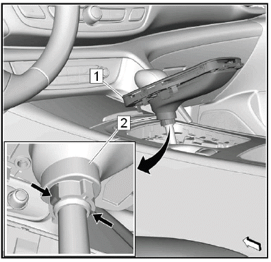
8. Push the transmission control lever boot bezel along with the retaining ring down to gain access to the transmission control lever knob fastener.
9.
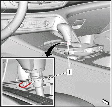
Transmission Control Lever Knob Fastener (1) - Remove.
10.
Transmission Control Lever Knob (1) @Transmission Control Lever (3) - Remove.
11. Transmission Control Lever Boot (2) @Transmission Control Lever - Remove.
Installation Procedure
1.
Transmission Control Lever Boot (2) @Transmission Control Lever (3) - Install.
2. Transmission Control Lever Knob (1) @Transmission Control Lever - Install.
3.
NOTE: Ensure the correct orientation of the transmission control lever knob fastener.
Transmission Control Lever Knob Fastener (1) - Install.
4. Check the transmission control lever knob for proper seat by pulling and twisting.
5.
Pull the transmission control lever boot bezel (1) along with the transmission control lever boot retaining ring (2) up.
6. Install the transmission control lever boot retaining ring to the transmission control lever knob. The 2 latches (arrows) of the transmission control lever boot retaining ring must engage noticeable.
7. Push the transmission control lever boot bezel down.
8.
Electrical Connector (1) - Connect.
9.
Install the transmission control lever boot bezel (1). First install the bezel at the rear then clip in the front of the bezel. Clip in 6 retainers (arrows).
10. Shift the transmission control lever into "P" position.
11. Release the parking brake.
TRANSMISSION CONTROL LEVER INSULATOR REPLACEMENT
Preliminary Procedures
1. Refer to Transmission Control Lever Knob Replacement.
2. Refer to Front Floor Console Replacement.
- Transmission Control Lever Insulator
TRANSMISSION CONTROL REPLACEMENT
Removal Procedure
1. Transmission Control Lever Knob - Remove - Refer to Transmission Control Lever Knob Replacement
2. Front Floor Console - Remove - Refer to Front Floor Console Replacement
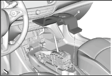
3.
Remove the transmission control lever insulator (1).
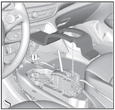
4. Front Floor Console Rear Air Front Duct - Remove - Refer to Front Floor Console Rear Air Duct Replacement (Front) Refer to Front Floor Console Rear Air Duct Replacement (Rear) 5.
Range Selector Lever Cable (1) @Transmission Control (2) - Remove.
- Push (arrows) the 2 lashes of the retainer (3) to disengage the range selector lever cable from the front of the transmission control.
- Remove the range selector lever cable with a suitable tool from the ball joint of the transmission control.
6.
Wiring Harness Clip (3) @Transmission Control (1) - Unclip.
7. Electrical Connector (2) @Transmission Control - Disconnect.
8.
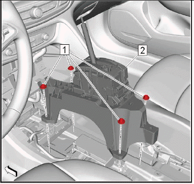
Transmission Control Nut (1) - Remove[4x].
9. Transmission Control (2) - Remove.
Installation Procedure
1.
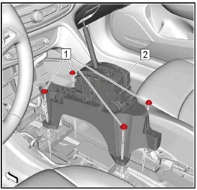
Transmission Control (1) - Install.
2. Transmission Control Nut (2) - Install and tighten[4x]9N.m (80 lb in).
3.
Electrical Connector (2) @Transmission Control (1) - Connect.
4. Wiring Harness Clip (3) @Transmission Control - Clip.
5.
Range Selector Lever Cable (1) @Transmission Control (2) - Install.
- Install the range selector lever cable to the ball joint of the transmission control.
- Push the range selector lever cable to the front of the transmission control. The retainer (3) must engage noticeable.
6. Front Floor Console Rear Air Front Duct - Install - Refer to Front Floor Console Rear Air Duct Replacement (Front) Refer to Front Floor Console Rear Air Duct Replacement (Rear).
7.
Install the transmission control lever insulator (1).
8. Front Floor Console - Install - Refer to Front Floor Console Replacement.
9. Transmission Control Lever Knob - Install - Refer to Transmission Control Lever Knob Replacement.
Adjustment Procedure
1. Range Selector Lever Cable - Adjust - Refer to Range Selector Lever Cable Adjustment.
TRANSMISSION FLUID DRAIN AND FILL
Draining Procedure
1. Raise and support the vehicle. Lifting and Jacking the Vehicle.
2.
Transmission Fluid Drain Plug (1) - Remove - Refer to Transmission Fluid Filler Overflow Tube and Drain Plug Removal.
3. Drain the transmission fluid into a suitable container.
4. Transmission Fluid Drain Plug - Install - Refer to Transmission Fluid Filler Overflow Tube and Drain Plug Installation.
5. Lower the vehicle.
Filling Procedure
1. Battery Tray - Remove - Refer to Battery Tray Replacement.
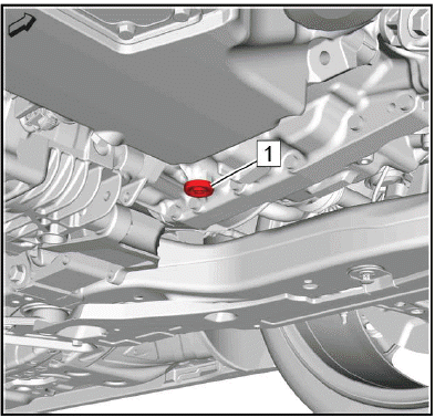
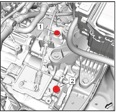
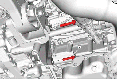
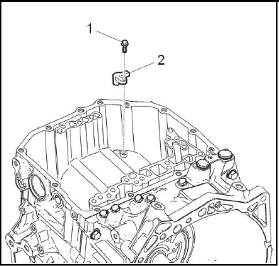
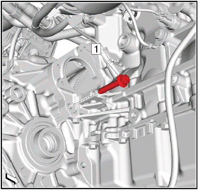
2.
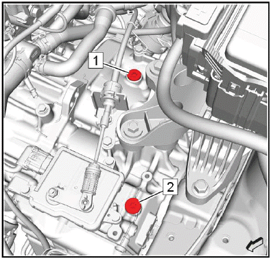
NOTE: The transmission oil filler plugs installed at locations 1 & 2 at the vehicle assembly plant are one-time-use. They have an interference fit and do not have O-rings. Once removed, these plugs must be replaced. The service part (replacement plug) available in the Electronic Parts Catalog (EPC) comes with an O-ring. Lubricate the seal with AW-1 fluid and install the O-ring prior to installing the plug. At each subsequent service, the service part plug (replacement plug) O-ring seal must be replaced. It is a one-time-use part. It is available separate from the plug in the EPC.
Remove a transmission oil filler plug (1) or (2), whichever is easier to access.
3. Fill the transmission to the proper level with the correct fluid. Approximate Fluid Capacities, and Adhesives, Fluids, Lubricants, and Sealers.
4. Install the transmission oil filler plug (1) or (2). Transmission Oil Filler Plug Replacement.
5. Battery Tray - Install - Refer to Battery Tray Replacement.
6. Raise the vehicle.
7. Check the transmission fluid level. Transmission Fluid Level and Condition Check.
8. Lower the vehicle.
9. Reset the learned values of the transmission control module. Learned Values Reset
TRANSMISSION OIL FILLER PLUG REPLACEMENT
Removal Procedure
1. Battery Tray - Remove - Refer to Battery Tray Replacement.
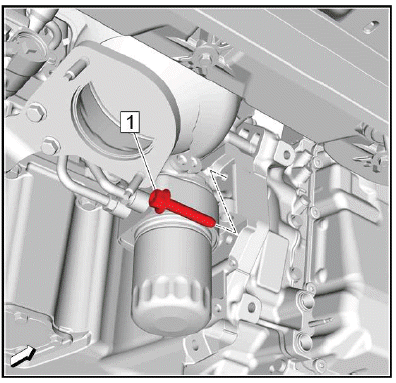
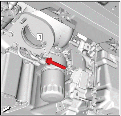
2.
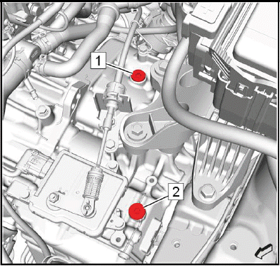
Remove a transmission oil filler plug (1) or (2).
Installation Procedure
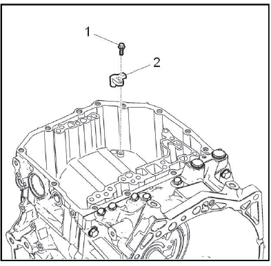
1.
NOTE: The transmission oil filler plugs installed at locations 1 & 2 at the vehicle assembly plant are one-time-use. They have an interference fit and do not have O-rings. Once removed, these plugs must be replaced. The service part (replacement plug) available in the Electronic Parts Catalog (EPC) comes with an O-ring. Lubricate the seal with AW-1 fluid and install the O-ring prior to installing the plug. At each subsequent service, the service part plug (replacement plug) O-ring seal must be replaced. It is a one-time-use part. It is available separate from the plug in the EPC.
CAUTION: Refer to Component Fastener Tightening Caution.
Install the transmission oil filler plug (1) or (2) and tighten to 30N.m (22 lb ft).
2. Battery Tray - Install - Refer to Battery Tray Replacement.
Vent Hose Replacement
Removal Procedure
1. Raise and support the vehicle. Lifting and Jacking the Vehicle.
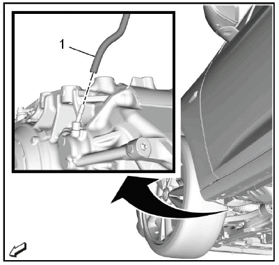
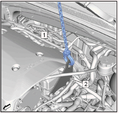
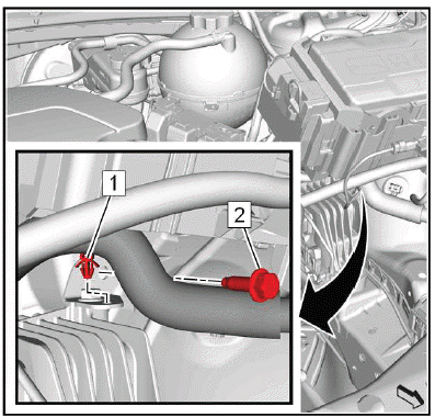
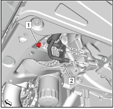
2.
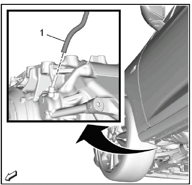
Transmission Vent Hose (1) @Transmission - Disconnect.
3. Lower the vehicle.
4.
Unclip the vent hose retainer (2) from the radiator surge tank (3).
NOTE: Note the routing of the vent hose.
5. Transmission Vent Hose (1) - Remove.
Installation Procedure
1.
NOTE: Ensure the vent hose is free of kinks and routed clear of sharp objects.
Transmission Vent Hose (1) - Install.
2. Clip the vent hose retainer (2) in the radiator surge tank (3).
3. Raise the vehicle.
4.
Transmission Vent Hose (1) @Transmission - Connect.
5. Lower the vehicle.
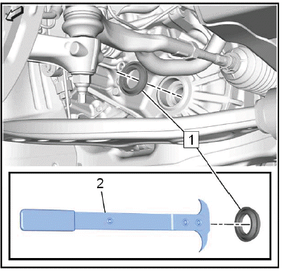
TORQUE CONVERTER FLUID SEAL REPLACEMENT
Special Tools
- DT-586 Remover Hook
- DT-21128 Pinion Seal Installer
- GE-6125 - 1B Slide Hammer
Equivalent regional tools: Refer to Special Tools
Removal Procedure
1. Transmission - Remove - Refer to Transmission Replacement.
2. Torque Converter - Remove - Refer to Torque Converter Replacement.
3.
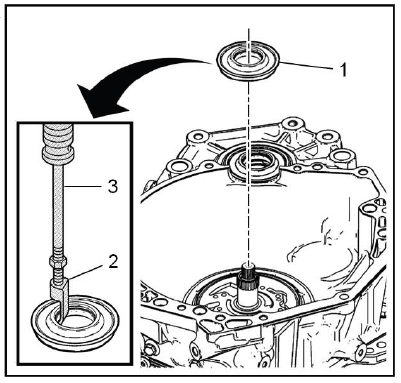
Torque Converter Fluid Seal (1) - Remove and DISCARD - Use the special tool: GE-6125 - 1B slide hammer (3) & DT-586 hook (2)
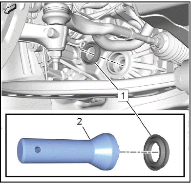
Installation Procedure
1.
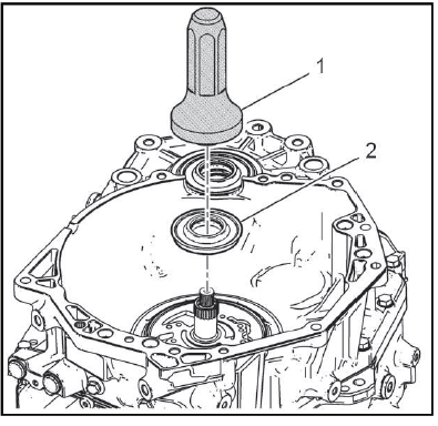
Torque Converter Fluid Seal (2) - Install NEW - Use the special tool: DT-21128 installer (1).
2. Torque Converter - Install - Refer to Torque Converter Replacement.
3. Transmission - Install - Refer to Transmission Replacement.
4. Reset the learned values of the transmission control module. Learned Values Reset.
5. Learn the gear selector neutral position. Gear Selector -N- Position Learn.
TRANSMISSION CONVERTER COVER REPLACEMENT
Preliminary Procedure
Refer to Lifting and Jacking the Vehicle.
- Transmission Rear Bolt
CAUTION: Tighten the transmission converter cover carefully to prevent it from becoming deformed. A deformed transmission converter cover may wear on the starting ring gear or the front wheel drive shaft resulting in noise emission and improper protecting properties.
CAUTION: Refer to Fastener Caution
Tighten 60N.m (44 lb ft)
- Transmission Lower Bolt
CAUTION: Tighten the transmission converter cover carefully to prevent it from becoming deformed. A deformed transmission converter cover may wear on the starting ring gear or the front wheel drive shaft resulting in noise emission and improper protecting properties.
Tighten 40N.m (30 lb ft)
- Transmission Converter Cover
TORQUE CONVERTER REPLACEMENT
Removal Procedure
1. Transmission - Remove - Refer to Transmission Replacement.
2.
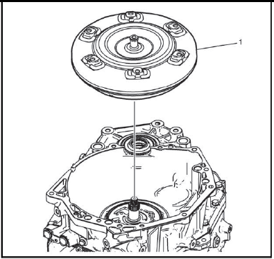
Torque Converter (1) @Transmission - Remove.
Installation Procedure
1.
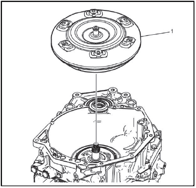
Torque Converter (1) @Transmission - Install.
2. Transmission - Install - Refer to Transmission Replacement.
3. Reset the learned values of the transmission control module. Learned Values Reset.
4. Learn the gear selector neutral position. Gear Selector -N- Position Learn.
Input Speed Sensor Replacement
Removal Procedure
1. Control Valve Body - Remove - Refer to Control Valve Body Replacement.
2.
Input Speed Sensor Bolt (1) - Remove.
3. Input Speed Sensor (2) - Remove.
Installation Procedure
1.
Input Speed Sensor (2) - Install.
CAUTION: Refer to Fastener Caution.
2. Input Speed Sensor Bolt (1) - Install and tighten5N.m (44 lb in).
3. Control Valve Body - Install - Refer to Control Valve Body Replacement.
4. Reset the learned values of the transmission control module. Learned Values Reset.
5. Learn the gear selector neutral position. Gear Selector -N- Position Learn.
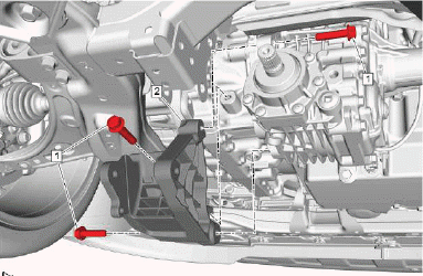
TRANSMISSION MOUNT REPLACEMENT
Special Tools
EN-45059 Angle Meter
Equivalent regional tools: Refer to Special Tools
Removal Procedure
1. Battery Tray - Remove - Refer to Battery Tray Replacement.
2. Charge Air Cooler Outlet Air Tube@Engine - Remove Charge Air Cooler Outlet Air Tube Replacement.
3.
Install the engine lifter (1) to the engine lift bracket (2) and apply tension to the chain.
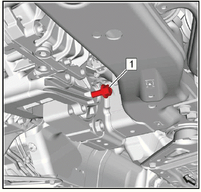
4.
Unclip the wiring harness clip (1) from the transmission mount brace.
5. Remove the transmission mount brace to body bolt (2).
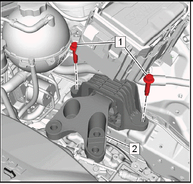
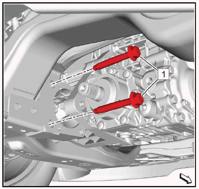
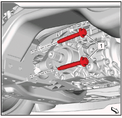
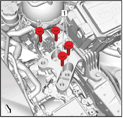
6.
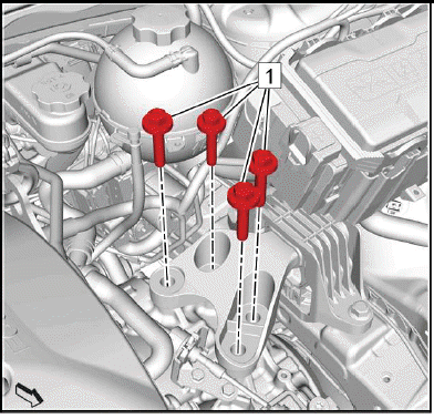
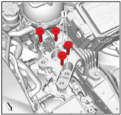
Remove and DISCARD the 4 transmission mount to transmission bolts (1).
7.
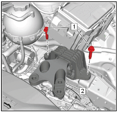
Remove the 2 transmission mount to body bolts (1).
8. Transmission Mount (2) - Remove.
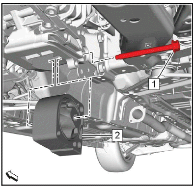
9.
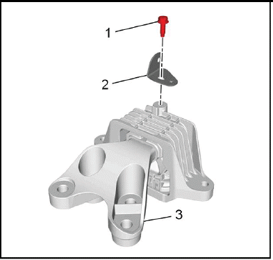
Remove the transmission mount brace to transmission mount bolt (1).
10. Remove the transmission mount brace (2) from the transmission mount (3).
Installation Procedure
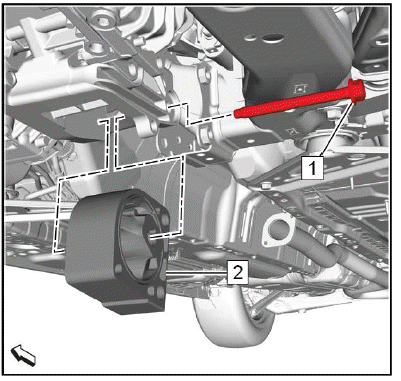
1.
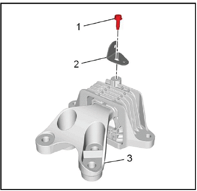
Install the transmission mount brace (2) to the transmission mount (3).
2. Install the transmission mount brace to transmission mount bolt (1) and hand tighten so that the transmission mount brace is still movable.
3.
Transmission Mount (2) - Install.
CAUTION: Refer to Fastener Caution.
4. Install the 2 transmission mount to body bolts (1) and tighten to 100N.m (74 lb ft).
5.
Install the transmission mount brace to body bolt (2) and tighten to 22N.m (16 lb ft).
6. Tighten the transmission mount brace to transmission mount bolt to 22N.m (16 lb ft).
7. Clip the wiring harness clip (1) into the transmission mount brace.
8.
CAUTION: Refer to Torque-to-Yield Fastener Caution.
Install 4 NEW transmission mount to transmission bolts (1) and tighten a first pass to 100N.m (74 lb ft).
9. Tighten the 4 NEW transmission mount to transmission bolts a final pass to an additional 60 - 75 degrees, using the EN-45059 meter.
10.
Remove the engine lifter (1) from the engine lift bracket (2).
11. Charge Air Cooler Outlet Air Tube@Engine - Install Charge Air Cooler Outlet Air Tube Replacement.
12. Battery Tray - Install - Refer to Battery Tray Replacement.
TRANSMISSION CONTROL MODULE REPLACEMENT
Removal Procedure
1. Set the parking brake.
2. Shift the transmission control into Neutral position.
3. Remove the battery tray. Battery Tray Replacement.
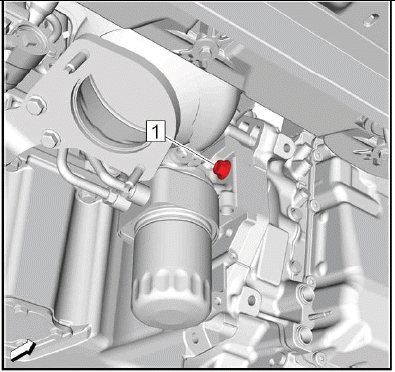
4.
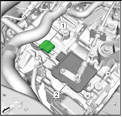
Electrical Connector (1) @Transmission Control Module (2) - Disconnect.
5. Range Selector Lever Cable@Range Selector Lever Cable Lever & Transmission Range Selector Lever Cable Bracket - Remove - Refer to Range Selector Lever Cable Replacement.
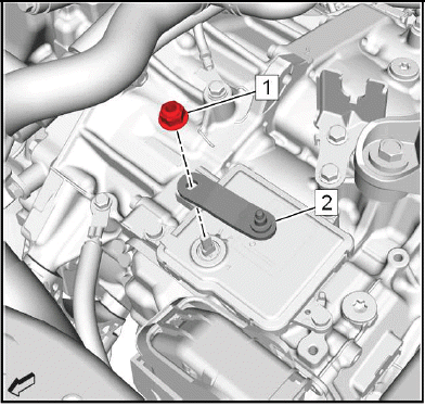
6.

WARNING: Hold the transmission range selector lever while removing or installing the lever retaining nut. Failure to hold the lever can cause damage to the transmission internal park system components which could allow the vehicle to roll when placed in the park position.
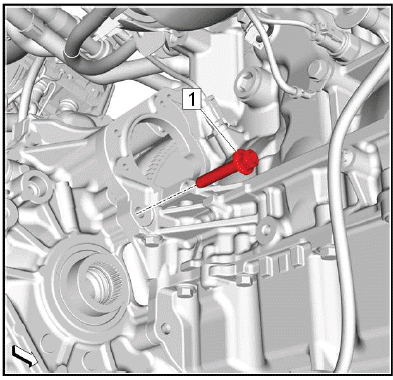
Transmission Range Selector Lever Nut (1) & Range Selector Lever Cable Lever (2) - Remove.
7.
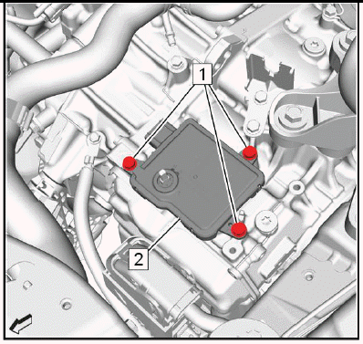
Transmission Control Module Bolt (1) - Remove[3x].
8. Transmission Control Module (2) - Remove.
Installation Procedure
1. Ensure that the transmission manual shaft is in Neutral position.
2.
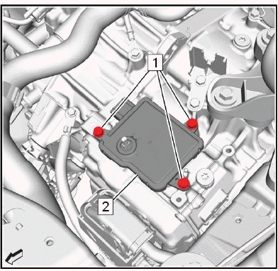
NOTE: Align the flats on the transmission shift shaft with the flats on the transmission control module.
Transmission Control Module (2) - Install.
CAUTION: Refer to Fastener Caution.
3. Transmission Control Module Bolt (1) - Install and tighten[3x]25N.m (18 lb ft).
4.
Range Selector Lever Cable Lever (2) - Install.
WARNING: Hold the transmission range selector lever while removing or installing the lever retaining nut. Failure to hold the lever can cause damage to the transmission internal park system components which could allow the vehicle to roll when placed in the park position.
5. Transmission Range Selector Lever Nut (1) - Install and tighten22N.m (16 lb ft).
6. Range Selector Lever Cable@Transmission Range Selector Lever Cable Bracket & Range Selector Lever Cable Lever - Install - Refer to Range Selector Lever Cable Replacement.
7.
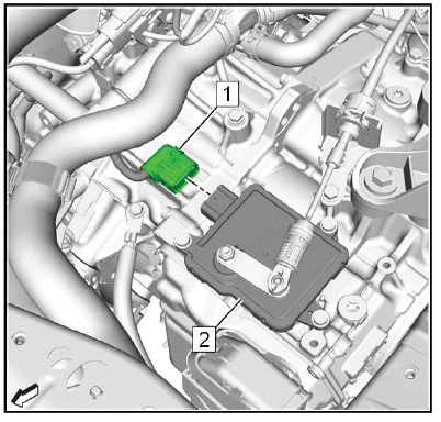
Electrical Connector (1) @Transmission Control Module (2) - Connect.
8. Install the battery tray.
9. Run all necessary programming and setup procedures.
Front Wheel Drive Shaft Seal Replacement - Left Side
Special Tools
- DT-446 Seal Installer
- EN-45000 Seal Remover
Equivalent regional tools: Refer to Special Tools
Removal Procedure
1. Raise and support the vehicle.
2. Front Wheel Drive Half Shaft- Left Side - Remove - Refer to Front Wheel Drive Half Shaft Replacement - Left Side.
3.
Left Front Wheel Drive Shaft Oil Seal (1) - Remove and DISCARD - Use the special tool: EN-45000 remover (2).
Installation Procedure
1.
Left Front Wheel Drive Shaft Oil Seal (1) - Install NEW - Use the special tool: DT-446 Installer (2).
2. Front Wheel Drive Half Shaft- Left Side - Install - Refer to Front Wheel Drive Half Shaft Replacement - Left Side.
3. Lower the vehicle.
CONTROL VALVE BODY COVER REPLACEMENT
Special Tools
EN-37228 Separating Tool
Equivalent regional tools: Refer to Special Tools
Removal Procedure
1. Raise and support the vehicle. Lifting and Jacking the Vehicle.
2. Drain the transmission fluid. Transmission Fluid Drain and Fill.
3. Front Compartment Air Deflector - Remove Front Compartment Air Deflector Replacement.
4.
Transmission Fluid Cooler Pipe Nut (1) - Remove.
5. Transmission Fluid Cooler Inlet and Outlet Pipe (2) @Transmission - Disconnect.
6. Transmission Fluid Cooler Inlet and Outlet Pipe - Position aside.
7.
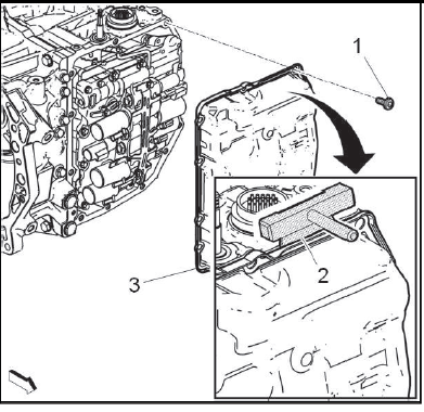
Control Valve Body Cover Bolt (1) - Remove[13x].
8. Slide the EN-37228 separating tool (2) around the perimeter of the control valve body cover to break the sealant.
9. Control Valve Body Cover (3) - Remove.
Installation Procedure
1. Clean all sealing surfaces.
2. Apply a bead of sealant to the perimeter of the sealing surface on the transmission case: Refer to Adhesives, Fluids, Lubricants, and Sealers for the correct type of sealant.
3. Control Valve Body Cover (2) - Install.
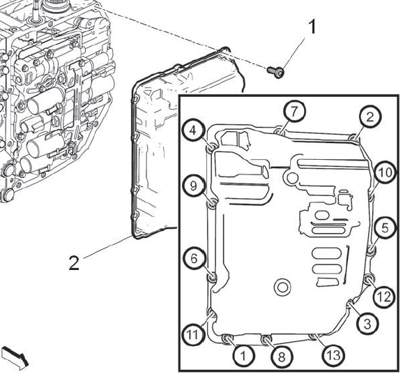
Fig. 1: Automatic Transmission Valve Body Bolts Tightening Sequence
4. Control Valve Body Cover Bolt (1) - Install and tighten[13x]13N.m (115 lb in) - Tighten in the sequence shown.
5.
Transmission Fluid Cooler Inlet and Outlet Pipe (2) - Reposition.
6. Transmission Fluid Cooler Inlet and Outlet Pipe@Transmission - Connect.
7. Transmission Fluid Cooler Pipe Nut (1) - Install and tighten10N.m (89 lb in).
8. Front Compartment Air Deflector - Install Front Compartment Air Deflector Replacement.
9. Lower the vehicle.
10. Fill the transmission to the proper level with NEW transmission fluid. Transmission Fluid Drain and Fill.
11. Reset the learned values of the transmission control module. Learned Values Reset.
CONTROL VALVE BODY REPLACEMENT
Removal Procedure
1. Transmission Control Module - Remove - Refer to Transmission Control Module Replacement.
2. Drain the transmission fluid. Transmission Fluid Drain and Fill.
3. Control Valve Body Cover - Remove - Refer to Control Valve Body Cover Replacement.
NOTE: Note the position and color of each electrical connector.
4. Wiring Harness Wire - Remove - Refer to Wiring Harness Wire Replacement.
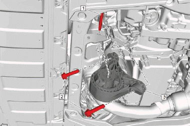
5.
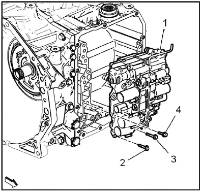
NOTE: The control valve body bolts have different lengths. Note the position of every bolt.
Control Valve Body Bolt (2, 3, 4) - Remove[8x]
- (2) = M6 x 31 [2x]
- (3) = M6 x 51 [1x]
- (4) = M6 x 21 [5x]
6. Control Valve Body (1) - Remove.
Installation Procedure
1. Control Valve Body (1) - Install.
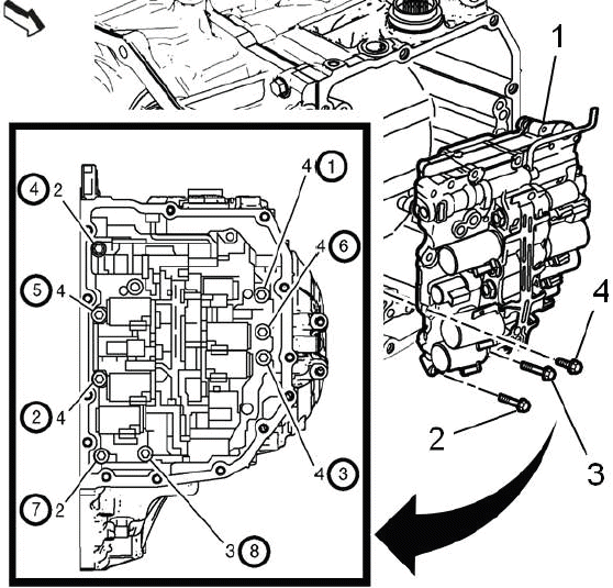
Fig. 2: Automatic Transmission Valve Body Control Unit Bolts Tightening
Sequence
Control Valve Body (1) - Install.
2. Control Valve Body Bolt (2, 3, 4) - Install and tighten[8x]10N.m (89 lb in) - Tighten the bolts in the sequence shown.
NOTE: The control valve body bolts have different lengths. Note the position of every bolt.
- (2) = M6 x 31 [2x]
- (3) = M6 x 51 [1x]
- (4) = M6 x 21 [5x]
3. Wiring Harness Wire - Install - Refer to Wiring Harness Wire Replacement.
4. Control Valve Body Cover - Install - Refer to Control Valve Body Cover Replacement.
5. Transmission Control Module - Install - Refer to Transmission Control Module Replacement.
6. Fill the transmission to the proper level with NEW transmission fluid. Transmission Fluid Drain and Fill.
7. Reset the learned values of the transmission control module. Learned Values Reset.
8. Learn the gear selector neutral position. Gear Selector -N- Position Learn.
Wiring Harness Wire Replacement
Removal Procedure
1. Transmission Control Module - Remove - Refer to Transmission Control Module Replacement.
2. Drain the transmission fluid. Transmission Fluid Drain and Fill.
3. Control Valve Body Cover - Remove - Refer to Control Valve Body Cover Replacement.
4.
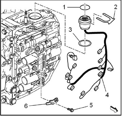
NOTE: Note the position and color of each electrical connector.
Wiring Harness - Remove
- Automatic Transmission Fluid Temperature Sensor Bolt (5) - Remove
- Automatic Transmission Fluid Temperature Sensor Clip (6) - Remove
- Automatic Transmission Wiring Harness Retainer (2) - Remove
- Disconnect all wiring harness connectors from the control valve body
- Wiring Harness Wire (4) - Remove
- Transmission Gasket (3) - Remove and DISCARD
- Automatic Transmission Wiring Connector Seal (1) - Remove and DISCARD
Installation Procedure
1.
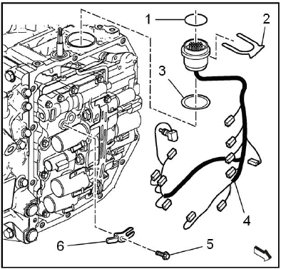
Wiring Harness - Install
- Automatic Transmission Wiring Connector Seal (1) - Install NEW
- Transmission Gasket (3) - Install NEW
- Wiring Harness Wire (4) - Install
- Connect all wiring harness connectors to the control valve body
- Automatic Transmission Wiring Harness Retainer (2) - Install
- Automatic Transmission Fluid Temperature Sensor Clip (6) - Install
- Automatic Transmission Fluid Temperature Sensor Bolt (5) - Install and tighten7N.m (62 lb in)
2. Control Valve Body Cover - Install - Refer to Control Valve Body Cover Replacement.
3. Transmission Control Module - Install - Refer to Transmission Control Module Replacement.
4. Fill the transmission to the proper level with NEW transmission fluid. Transmission Fluid Drain and Fill.
5. Reset the learned values of the transmission control module. Learned Values Reset.
6. Learn the gear selector neutral position. Gear Selector -N- Position Learn.
TRANSMISSION REAR MOUNT BRACKET REPLACEMENT
Preliminary Procedure
Refer to Transmission Rear Mount Replacement.
- Transmission Rear Mount Bracket Bolt [3x]
CAUTION: Refer to Fastener Caution
CAUTION: Refer to Torque-to-Yield Fastener Caution
Procedure
Install NEW bolts. - Do NOT reuse the old bolt.
Tighten
- First Pass:100N.m (74 lb ft)
- Final Pass:60 - 75 degrees
Special Tools
EN-45059 Angle Meter
Equivalent regional tools: Refer to Special Tools
- Transmission Rear Mount Bracket
TRANSMISSION REAR MOUNT REPLACEMENT
Special Tools
- EN-45059 Angle Meter
Equivalent regional tools: Refer to Special Tools
Removal Procedure
1. Raise and support the vehicle. Lifting and Jacking the Vehicle.
2. Charge Air Cooler Outlet Air Tube - Remove - Refer to Charge Air Cooler Outlet Air Tube Replacement.
3. Exhaust Front Pipe - Remove - Refer to Exhaust Front Pipe Replacement (FWD LGX) Refer to Exhaust Front Pipe Replacement (LTG) Refer to Exhaust Front Pipe Replacement (AWD LGX).
4. Propeller Shaft - Remove - Refer to Propeller Shaft Replacement.
5. Transmission Front Mount - Remove - Refer to Transmission Front Mount Replacement.
6. Charge Air Cooler Inlet Air Tube - Remove - Refer to Charge Air Cooler Inlet Air Tube Replacement.
7. Front Compartment Air Deflector - Remove - Refer to Front Compartment Air Deflector Replacement.
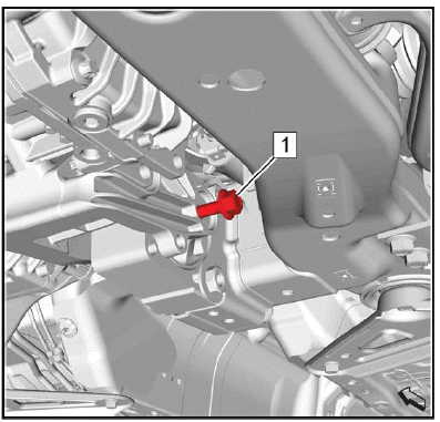
8.
Remove and DISCARD the 2 transmission rear mount bolts (1).
9.
Loosen the transmission rear mount through bolt (1).
NOTE: A second technician is required.
10. Push the engine / transmission unit far enough forward to get space for the removal of the transmission rear mount through bolt.
11.
Remove the transmission rear mount through bolt (1).
12. Transmission Rear Mount (2) - Remove.
13. Release the engine / transmission unit to bring it into original position.
Installation Procedure
NOTE: A second technician is required.
1. Push the engine / transmission unit far enough forward to get space for the installation of the transmission rear mount through bolt.
2.
Transmission Rear Mount (2) - Install.
3. Install the transmission rear mount through bolt (1).
4. Release the engine / transmission unit to bring it into original position.
5.
CAUTION: Refer to Fastener Caution.
Tighten the transmission rear mount through bolt (1) to 100N.m (74 lb ft).
6.
CAUTION: Refer to Torque-to-Yield Fastener Caution.
Install the 2 NEW transmission rear mount bolts (1) and tighten a first pass to 100N.m (74 lb ft).
7. Tighten the 2 NEW transmission rear mount bolts a final pass to 120 - 135 degrees, using the EN-45059 meter.
8. Front Compartment Air Deflector - Install - Refer to Front Compartment Air Deflector Replacement.
9. Charge Air Cooler Inlet Air Tube - Remove - Refer to Charge Air Cooler Inlet Air Tube Replacement.
10. Transmission Front Mount - Install - Refer to Transmission Front Mount Replacement.
11. Propeller Shaft - Install - Refer to Propeller Shaft Replacement.
12. Exhaust Front Pipe - Install - Refer to Exhaust Front Pipe Replacement (FWD LGX) Refer to Exhaust Front Pipe Replacement (LTG) Refer to Exhaust Front Pipe Replacement (AWD LGX).
13. Charge Air Cooler Outlet Air Tube - Remove - Refer to Charge Air Cooler Outlet Air Tube Replacement.
14. Lower the vehicle.
TRANSMISSION FRONT MOUNT REPLACEMENT
Preliminary Procedure
Refer to Lifting and Jacking the Vehicle.
- Transmission Front Mount Through Bolt
CAUTION: Refer to Fastener Caution
Tighten 100N.m (74 lb ft)
- Transmission Front Mount to Transmission Bolt [2x]
Tighten 100N.m (74 lb ft)
- Transmission Front Mount
TRANSMISSION REPLACEMENT
Special Tools
- EN-45059 Angle Meter
- EN-51007 Engine Support Fixture
Equivalent regional tools: Refer to Special Tools
Removal Procedure
1. Battery Tray - Remove - Refer to Battery Tray Replacement.
2. Charge Air Cooler Outlet Air Tube - Remove - Refer to Charge Air Cooler Outlet Air Tube Replacement.
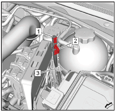
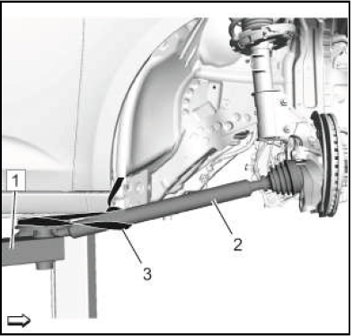
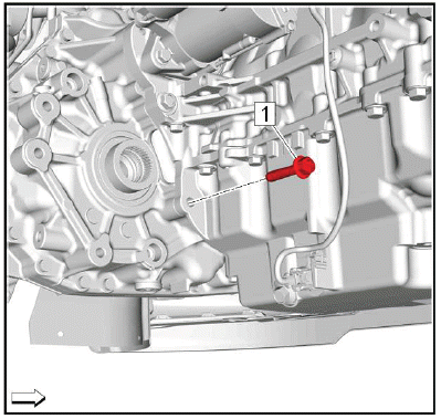
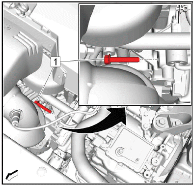
3.
Range Selector Lever Cable (4) @Range Selector Lever Cable Lever (3) - Remove.
4. Range Selector Lever Cable@Transmission Range Selector Lever Cable Bracket (2) - Remove.
Push (arrows) the latches of the retainer (1) to release the range selector lever cable from the bracket.
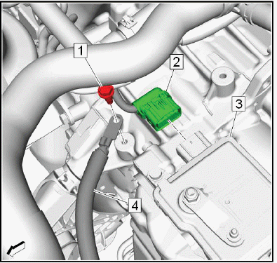
5.
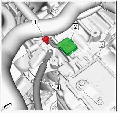
Electrical Connector (2) @Transmission Control Module (3) - Disconnect.
6. Battery Negative Cable Ground Bolt (1) - Remove.
7. Battery Negative Cable (4) - Position aside.
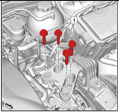
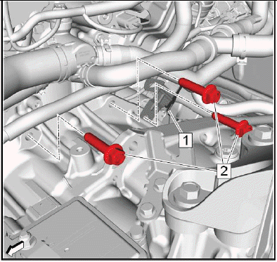
8.
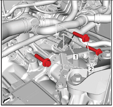
NOTE: The graphic is shown without generator positive cable for the sake of clarity.
Remove the 3 transmission upper bolts (2).
9. Generator and Starter Cable Bracket (1) - Position aside.
10.
Remove the transmission front upper bolt (1).
11. Raise and support the vehicle. Lifting and Jacking the Vehicle.
12. Transmission Fluid - Drain - Refer to Transmission Fluid Drain and Fill.
13. Exhaust Front Pipe - Remove - Refer to Exhaust Front Pipe Replacement (FWD LGX) Refer to Exhaust Front Pipe Replacement (LTG) Refer to Exhaust Front Pipe Replacement (AWD LGX).
14. Propeller Shaft - Remove - Refer to Propeller Shaft Replacement.
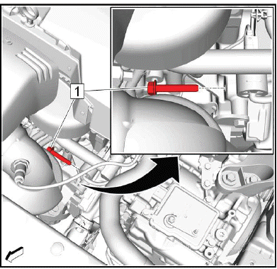
15.
Remove the transmission lower bolt (1).
16. Drivetrain and Front Suspension Cradle - Remove - Refer to Drivetrain and Front Suspension Cradle Replacement (LGX) Refer to Drivetrain and Front Suspension Cradle Replacement (LTG).
17. Transmission Front Mount - Remove - Refer to Transmission Front Mount Replacement.
18. Transmission Rear Mount Bracket - Remove - Refer to Transmission Rear Mount Bracket Replacement.
19. Transmission Fluid Cooler Inlet and Outlet Pipe@Transmission - Remove - Refer to Transmission Fluid Cooler Inlet and Outlet Pipe Replacement (AF50-8) Plug and/or cap the pipes and transmission to prevent contamination.
20. Oil Pump Flow Control Valve Heat Shield - Remove - Refer to Oil Pump Flow Control Valve Heat Shield Replacement.
21. Front Wheel Drive Half Shaft- Right Side@Transfer Case - Disconnect - Refer to Front Wheel Drive Half Shaft Replacement - Right Side (AWD) Refer to Front Wheel Drive Half Shaft Replacement - Right Side (FWD).
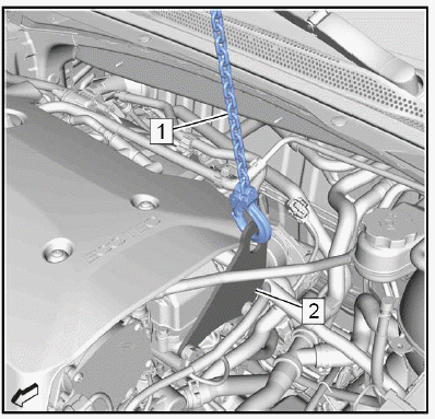
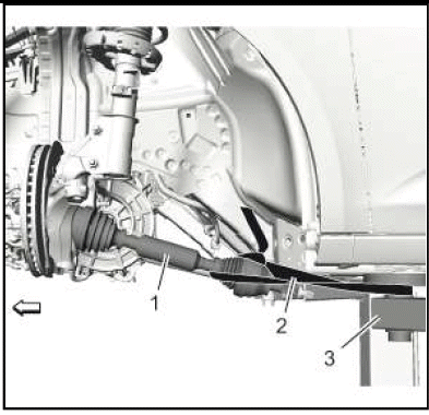
22.
Secure the right drive shaft (2) to the hoist (1), using a lashing strap (3).
23. Front Wheel Drive Half Shaft- Left Side@Transmission - Disconnect - Refer to Front Wheel Drive Half Shaft Replacement - Left Side.
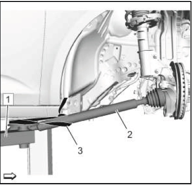
24.
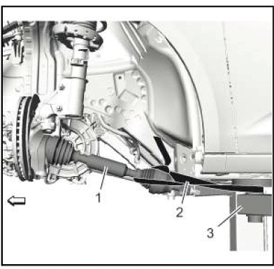
Secure the left drive shaft (1) to the hoist (3), using a lashing strap (2).
25. Power Transfer Unit Case - Remove - Refer to Power Transfer Unit Case Replacement.
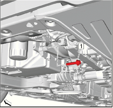
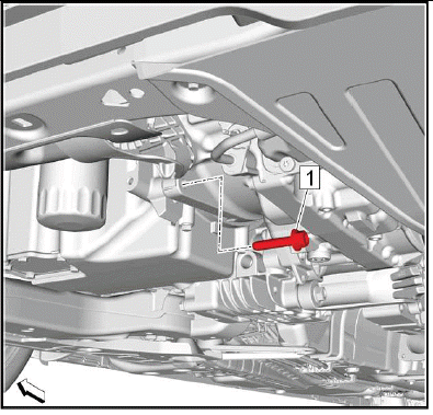
26.
Remove the transmission lower bolt (1).
27. Starter - Remove - Refer to Starter Replacement (2.0L LTG) Refer to Starter Replacement (3.6L LGX).
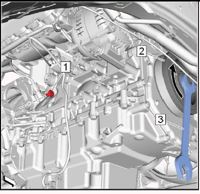
28.
Torque Converter@Flex Plate - Loosen
- Turn the engine at the crankshaft balancer (2) clockwise (arrow) with a suitable tool (3), until a torque converter bolt (1) shows up.
- Remove and DISCARD the first torque converter bolt.
- Turn the engine at the crankshaft balancer clockwise 60 degrees.
- Remove and DISCARD the next torque converter bolt.
- Repeat the previous 2 steps until the sixth torque converter bolt is removed.
29. Lower the vehicle.
30. Transmission Vent Hose - Remove - Refer to Vent Hose Replacement.
31. Engine Support Fixture - Install - Refer to Engine Support Fixture.
32. Apply tension to the hooks of the EN-51007 fixture.
33.
34. Remove and DISCARD the 4 transmission mount to transmission bolts (1).
35. Lower the engine/transmission unit about 5.5cm (2.16in), using the EN-51007 fixture.
36. Raise the vehicle.
37. Support the transmission with a suitable jack.
38.
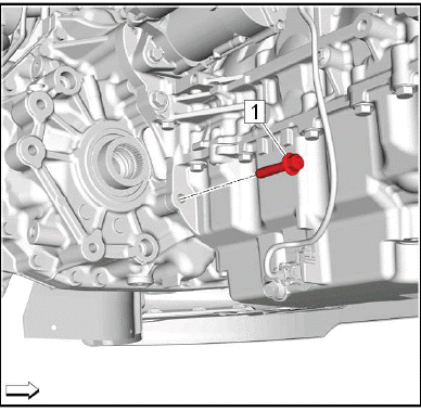
Remove the transmission rear bolt (1).
39.
NOTE: This is the last transmission bolt.
Remove the transmission front lower bolt (1).
NOTE: A second technician is required.
40. Separate the transmission from the engine.
41. Lower the transmission jack far enough to remove the transmission.
Installation Procedure
1. Transfer components as necessary.
2. If the removed transmission will be reinstalled, clean the threads of the torque converter.
NOTE: A second technician is required.
3. Raise the transmission with the transmission jack and position the transmission to the engine.
4.
CAUTION: Refer to Fastener Caution
Install the transmission front lower bolt (1) and tighten a first pass to 10N.m (89 lb in), in order to align the transmission and the engine flush.
5.
Install the transmission rear bolt (1) and tighten to 58N.m (43 lb ft).
6.
Tighten the transmission front lower bolt a final pass to 58N.m (43 lb ft).
7. Remove the transmission jack.
8. Lower the vehicle.
9. Raise the engine/transmission unit into original position, using the EN-51007 fixture.
10.
CAUTION: Refer to Torque-to-Yield Fastener Caution.
Install 4 NEW transmission mount to transmission bolts (1) and tighten a first pass to 100N.m (74 lb ft).
11. Tighten the 4 NEW transmission mount to transmission bolts (1) a final pass to 60 - 75 degrees, using the EN- 45059 meter.
12. Engine Support Fixture - Remove - Refer to Engine Support Fixture.
13. Transmission Vent Hose - Install - Refer to Vent Hose Replacement.
14. Raise the vehicle.
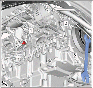
15.
Torque Converter@Flex Plate - Install.
- Turn the engine at the crankshaft balancer (2) clockwise (arrow) with a suitable tool (3), until a torque converter thread shows up.
NOTE: Service may offer bolts without microencapsulated thread locking adhesive. If this is the case, apply thread locking adhesive to the bolt.
- Install the first NEW torque converter bolt (1) and tighten to 60N.m (44 lb ft).
- Turn the engine at the crankshaft balancer clockwise 60 degrees.
- Install the next NEW torque converter bolt and tighten to 60N.m (44 lb ft).
- Repeat the previous 2 steps until the sixth torque converter bolt is installed.
16. Starter - Install - Refer to Starter Replacement (2.0L LTG) Refer to Starter Replacement (3.6L LGX).
17.
Install the transmission lower bolt (1) and tighten to 58N.m (43 lb ft).
18. Power Transfer Unit Case - Install - Refer to Power Transfer Unit Case Replacement.
19.
Remove the left drive shaft (1) from the hoist (3).
20. Front Wheel Drive Half Shaft- Left Side@Transmission - Connect - Refer to Front Wheel Drive Half Shaft Replacement - Left Side.
21.
Remove the right drive shaft (2) from the hoist (1).
22. Front Wheel Drive Half Shaft- Right Side@Transfer Case - Connect - Refer to Front Wheel Drive Half Shaft Replacement - Right Side (AWD) Refer to Front Wheel Drive Half Shaft Replacement - Right Side (FWD).
23. Oil Pump Flow Control Valve Heat Shield - Install - Refer to Oil Pump Flow Control Valve Heat Shield Replacement.
24. Transmission Fluid Cooler Inlet and Outlet Pipe@Transmission - Install - Refer to Transmission Fluid Cooler Inlet and Outlet Pipe Replacement (AF50-8).
25. Transmission Rear Mount Bracket - Install - Refer to Transmission Rear Mount Bracket Replacement.
26. Transmission Front Mount - Install - Refer to Transmission Front Mount Replacement.
27. Drivetrain and Front Suspension Cradle - Install - Refer to Drivetrain and Front Suspension Cradle Replacement (LGX) Refer to Drivetrain and Front Suspension Cradle Replacement (LTG).
28.
Install the transmission lower bolt (1) and tighten to 58N.m (43 lb ft).
29. Propeller Shaft - Install - Refer to Propeller Shaft Replacement.
30. Exhaust Front Pipe - Install - Refer to Exhaust Front Pipe Replacement (FWD LGX) Refer to Exhaust Front Pipe Replacement (LTG) Refer to Exhaust Front Pipe Replacement (AWD LGX).
31. Lower the vehicle.
32.
Install the transmission front upper bolt (1) and tighten to 58N.m (43 lb ft).
33.
NOTE: The graphic is shown without generator positive cable for the sake of clarity.
Generator and Starter Cable Bracket (1) - Reposition.
34. Install the 3 transmission upper bolts (2) and tighten to 58N.m (43 lb ft).
35.
Battery Negative Cable (4) - Reposition.
36. Battery Negative Cable Ground Bolt (1) - Install and tighten22N.m (16 lb ft).
37. Electrical Connector (2) @Transmission Control Module (3) - Connect.
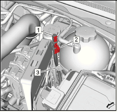
38.
Range Selector Lever Cable (4) @Transmission Range Selector Lever Cable Bracket (2) - Install.
Push the range selector lever cable into the bracket. The retainer (1) must engage noticeable.
39. Range Selector Lever Cable@Range Selector Lever Cable Lever (3) - Install.
40. Range Selector Lever Cable - Adjust - Refer to Range Selector Lever Cable Adjustment.
41. Charge Air Cooler Outlet Air Tube - Install - Refer to Charge Air Cooler Outlet Air Tube Replacement.
42. Battery Tray - Install - Refer to Battery Tray Replacement.
43. Transmission Fluid - Fill - Refer to Transmission Fluid Drain and Fill.
44. Run all necessary programming and setup procedures. Control Module: References.
45. Road test the vehicle.
READ NEXT:
 Repair Instructions - Off Vehicle
Torque Converter Assembly Removal
Torque Converter
TORQUE CONVERTER FLUID SEAL REMOVAL
Torque Converter Fluid Seal
Special Tools
EN-45000 Seal Remover
Equivalent regional tools: Refer to S
Description and Operation
Transmission Identification Information
For automatic transmission AF50, the identification plate is on the top of
the transmission housing.
Aisin Warner transmission type
Fabrication line 1 = 00
Special Tools and Equipment
SPECIAL TOOLS
DT-26941
J-26941
Remover
DT-37228
J-37228
Seal Cutter
DT-43911
J-43911
Selector Shaft Seal
Remover
DT-44215
J-44215
Rear Seal Installer
DT-44809
J-44809
Output Shaft Seal
Installer
SEE MORE:
Appearance Care
Exterior Care
Locks
Locks are lubricated at the factory.
Use a de-icing agent only when
absolutely necessary, and have the
locks greased after using.
Washing the Vehicle
To preserve the vehicle's finish,
wash it often and out of direct
sunlight.
Caution:
Do not use petroleum-based,
acidic, or abr
Description and Operation
SUPPLEMENTAL INFLATABLE RESTRAINT SYSTEM DESCRIPTION AND OPERATION
SIR System Overview
The supplemental inflatable restraint (SIR) system supplements the protection
offered by the seat belts. The SIR
system contains an inflatable restraint sensing and diagnostic module (SDM), air
bags, seat belt p
