Opel Insignia: Introduction
Arrows and Symbols, Acronyms and Units
ARROWS AND SYMBOLS
This service manual uses various symbols in order to describe different service operations.
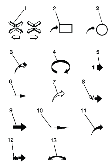
- Front of Vehicle
- View Detail
- Ambient Air Mixed with Another Gas or Indicate Temperature Change
- Motion or Direction
- View Angle
- Dimension (1:2)
- Ambient/Clean Air Flow or Cool Air Flow
- Lubrication Point - Oil or Fluid
- Task Related
- Sectioning (1:3)
- Gas Other Than Ambient Air or Hot Air Flow
- Lubrication Point - Grease or Jelly
- Multidirectional Arrow
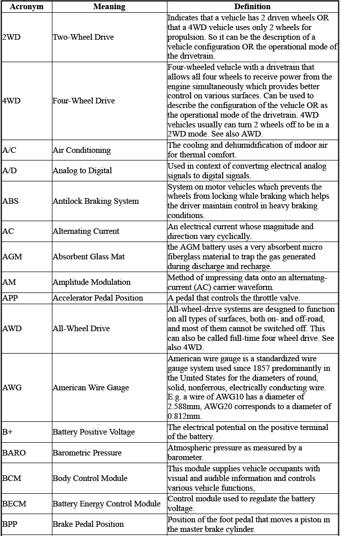
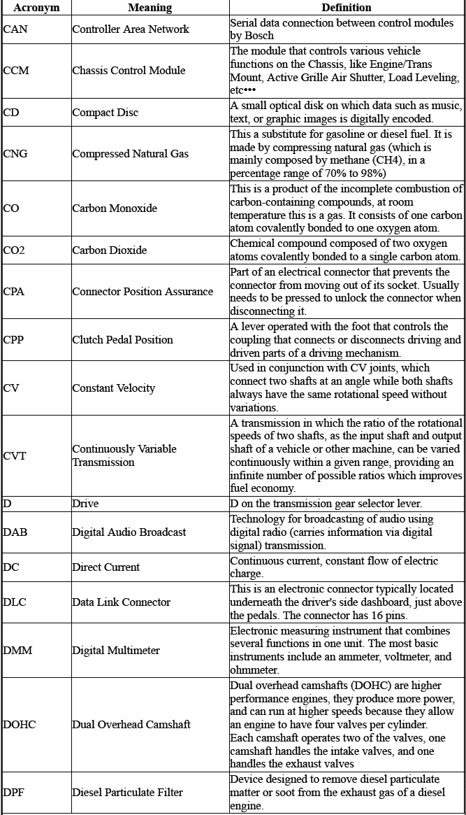
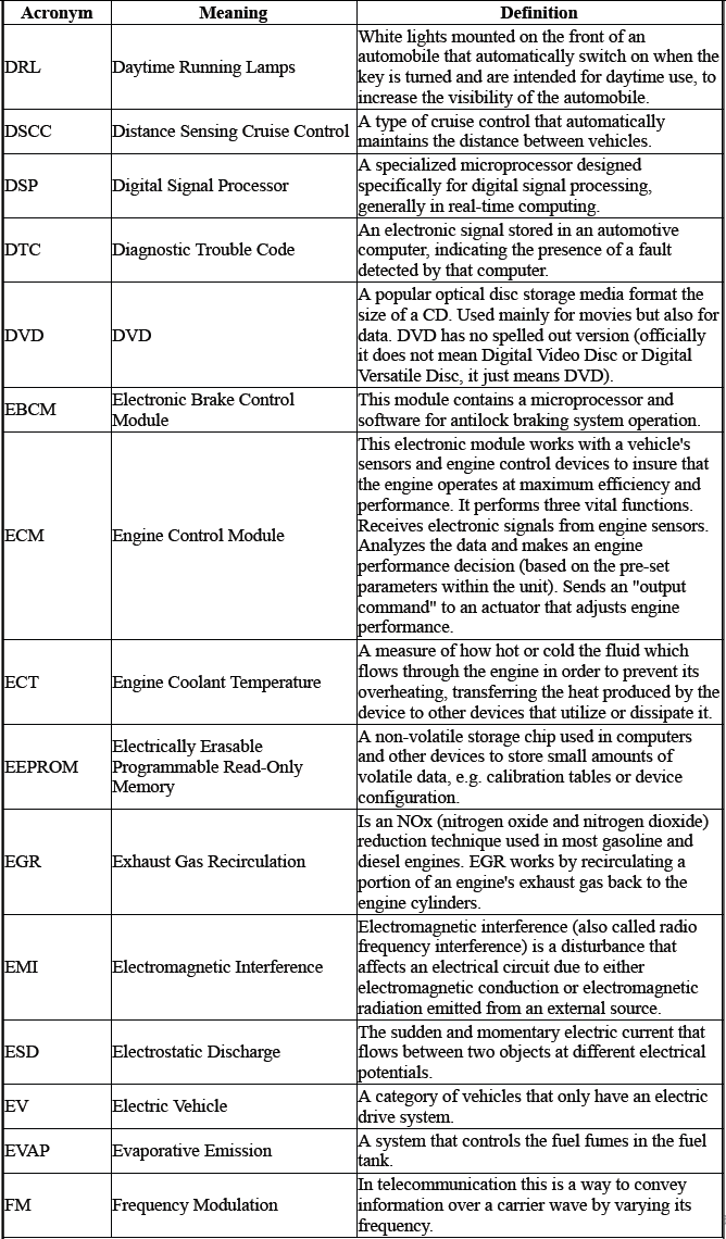
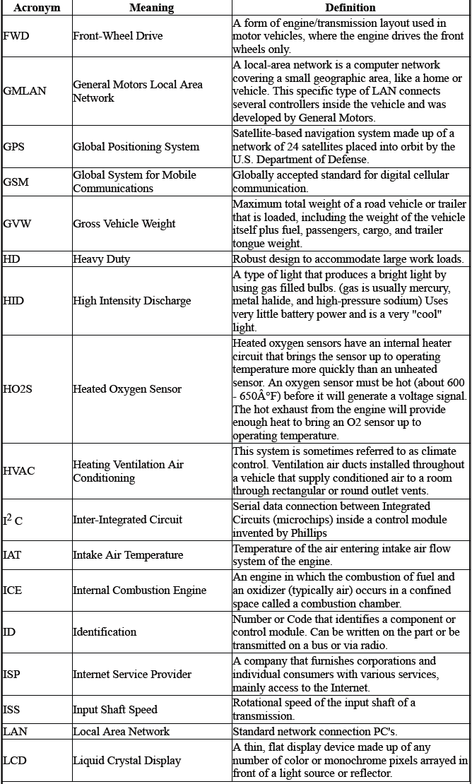
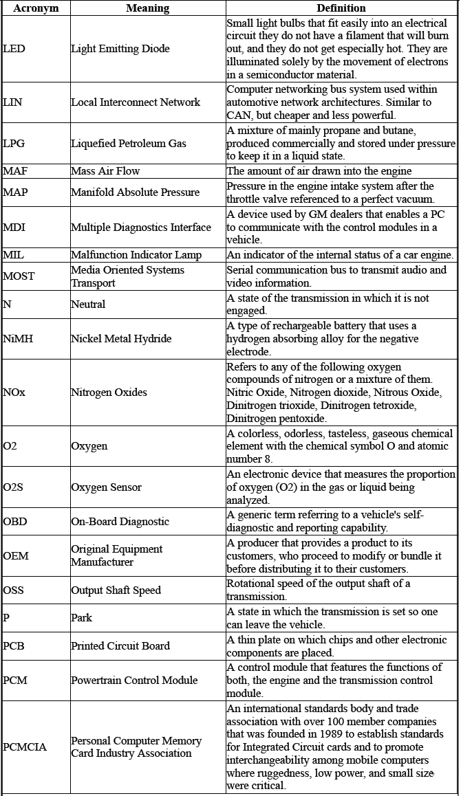
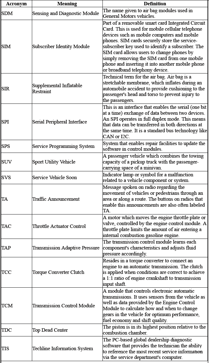
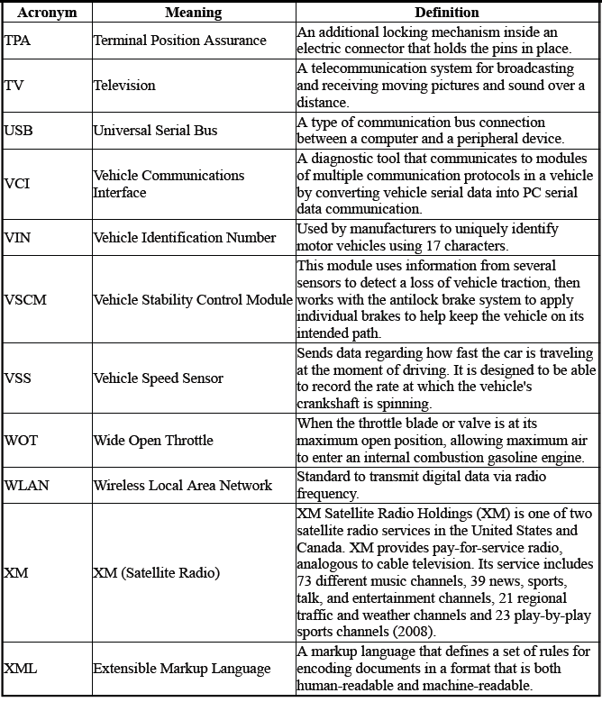
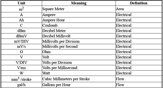
ACRONYMS AND UNITS
Acronyms

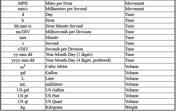
Units

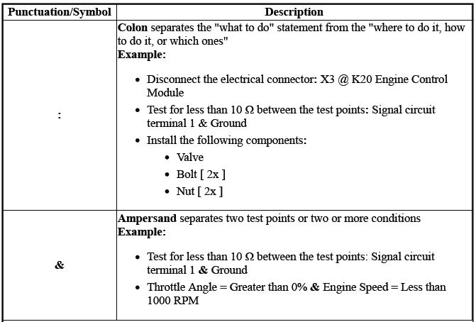
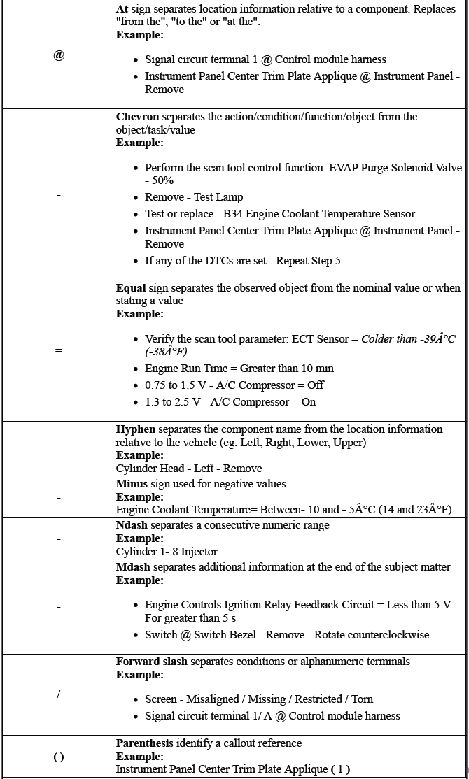
TEXT FORMATS AND SYMBOLS
These punctuation marks and symbols are used in the service information to separate information, values, data, and text.
NOTE: In the examples, the punctuation marks and symbols are bold only to highlight them; in the service information, they are not bold.
GRAPHIC COLORS AND GRAPHIC SYMBOLS
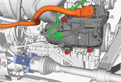
- Orange - High voltage electrical connectors and harnesses being removed or installed.
- Green - Electrical connectors and harnesses being removed or installed.
- Red - Fasteners being removed or installed.
- Dark Gray - Standout color that shows the component being removed or installed.
- Light Gray - Background detail to show component location.
- Light Blue - Special tool being used.
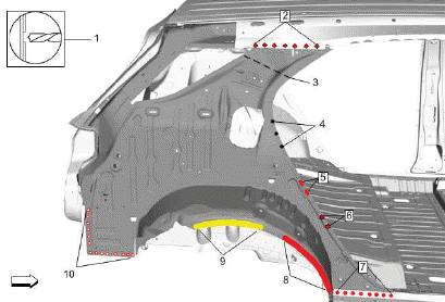
- Drill through top layer of material only
- Structural Rivet
- Sectioning Location
- Drill Hole
- Mig Braze Slot
- Self-Piercing Rivet
- Mig/Mag Plug Weld
- Adhesive
- Apply Heat
- Resistance Spot Weld
CUSTOMER CONCERN VERIFICATION SHEETS
The GM Customer Concern Verification Sheets have been designed to improve communications between the service customer and the technician. The more clearly the technician understands the concern and its symptoms, the more likely the concern will be fixed right the first time.
The GM-wide Customer Concern Verification Sheets are available in GM Global Connect. The Customer Concern Verification Sheets may be printed and reproduced locally.
TRAINING
Dealers
All U.S. GM Dealers participating in the Center of Learning / GM Service Technical College (STC) Programs can enroll through the Center of Learning website at https://www.centerlearning.com. Within the website, there are individual training paths that are designed to assist in planning the training needs for each individual and their job role. Dealers who have questions about Center of Learning Training should contact the Center of Learning help desk at 1-888-748-2687. The help desk is available Monday through Friday, 8:00 am - 9:00 pm Eastern Standard Time, excluding holidays. For GM Access support, contact the GM Access Help Desk at 1-888-337-1010.
Fleets
GM Fleet customers with GM Warranty In-Shop agreements are able to participate in service technical training through the Center of Learning/GM Service Technical College (STC).
Assistance for GM fleet registered customers using GM STC training is provided by the Center of Learning help desk at 1-888-748-2687. The help desk is available Monday through Friday, 8:00 am - 9:00 pm Eastern Standard Time, excluding holidays. For GM Access support, contact the GM Access Help Desk at 1-888-337-1010.
Most GM STC course materials have associated charges.
To purchase authentic GM STC Training Materials, contact the GM Training Materials Headquarters at 1-800-393-4831.
Non-GM Dealer Technicians
Technician training for non-GM dealers is available through ACDelco. This training is for ACDelco PSC and Fleet program members employed in the automotive or truck service industry.
ACDelco courses are available at approved GM STC Training Centers. Availability and schedules can be obtained by calling 1-800-825-5886 (prompt 1) or contact us via the web at www.acdelcotechconnect.com and select the Training tab. Seminars are also offered through the ACDelco Warehouse Distribution channel. Contact your Local ACDelco representative or distributor directly for more information.
Vehicle, Engine and Transmission ID and VIN Location, Derivative and Usage
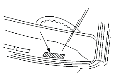
The vehicle identification number (VIN) plate is the legal identifier of the vehicle. The VIN plate is located on the upper left corner of the instrument panel (I/P) and can be seen through the windshield from the outside of the vehicle:
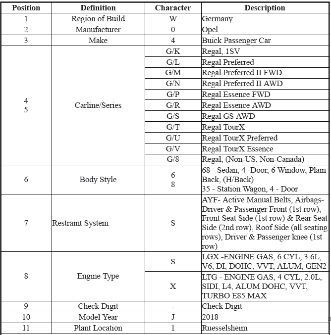

2.0L (LTG) Engine ID and VIN Derivative Location
Engine Identification.
3.6L (LGX) Engine ID and VIN Derivative Location
Engine Identification.
Automatic Transmission - 9T50 (M3D) and 9T60 (M3T) Transmission ID and VIN Derivative Location
Transmission Identification Information.
Automatic Transmission - Aisin AF50-8 (MRC) Transmission ID and VIN Derivative Location
Transmission Identification Information.
VEHICLE CERTIFICATION, TIRE PLACARD, ANTI-THEFT, AND SERVICE PARTS ID LABEL
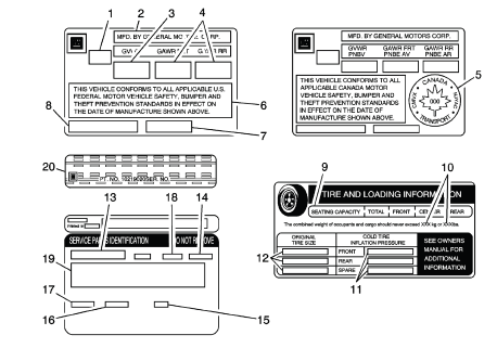
Vehicle Certification Label
The vehicle certification label is located on the left hand side of the B pillar and displays the following assessments:
- Gross Vehicle Weight Rating (GVWR)
- Gross Axle Weight Rating (GAWR), front and rear
- The gross vehicle weight (GVW) is the weight of the vehicle and
everything it carries. The
gross vehicle weight must not exceed the Gross Vehicle Weight Rating.
Include the
following items when figuring the GVW:
- The base vehicle weight (factory weight)
- The weight of all vehicles accessories
- The weight of the driver and the passengers
- The weight of the cargo
- Name of Manufacturer
- Gross Vehicle Weight Rating
- Gross Axle Weight Rating (Front, Rear)
- Canadian Safety Mark (w/RPO Z49)
- Certification Statement
- Vehicle Class Type (Pass Car, etc.)
- Vehicle Identification Number
- Date of Manufacture (Mo/Yr)
Tire Placard
The tire placard label is located on the forward portion of the center pillar and displays the following assessments:
- Specified Occupant Seating Positions
- Maximum Vehicle Capacity Weight
- Tire Pressure, Front, Rear, and Spare (Cold)
- Original Equipment Tire Size
Service Parts ID Label
The vehicle service parts identification label is located in the rear compartment attached to the left side of the spare tire well. The label is use to help identify the vehicle original parts and options.
- Vehicle Identification Number
- Engineering Model Number (Vehicle Division, Line, and Body Style)
- Interior Trim Level and Decor
- Exterior (Paint Color) WA Number
- Paint Technology
- Special Order Paint Colors and Numbers
- Vehicle Option Content
Anti-Theft Label
- The Federal law requires that General Motors label certain body parts on
this vehicle
with the VIN. The purpose of the law is to reduce the number of motor
vehicle thefts
by helping in the tracing and recovery of parts from stolen vehicles.
Labels are permanently affixed to an interior surface of the part. The label on the replacement part contains the letter R, the manufacturer's logo, and the DOT symbol.
The anti-theft label must be covered before any painting, rustproofing procedures, and uncovered after the procedures. Failure to follow the precautionary steps may result in liability for violation of the Federal Vehicle Theft Prevention Standard and possible suspicion to the owner that the part was stolen.
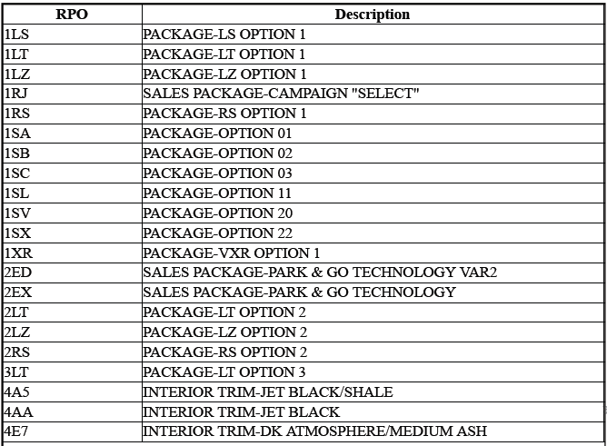
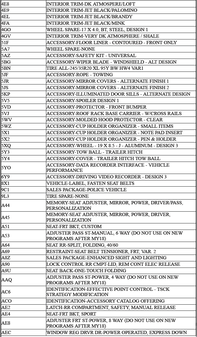
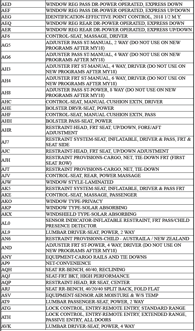
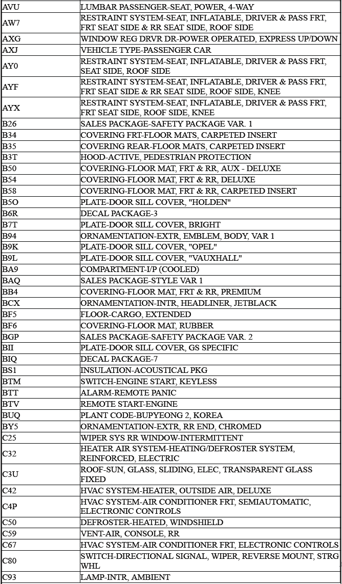
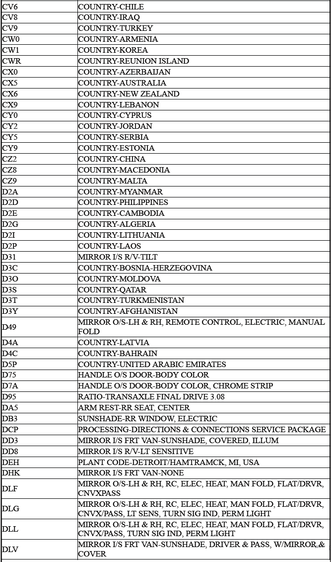
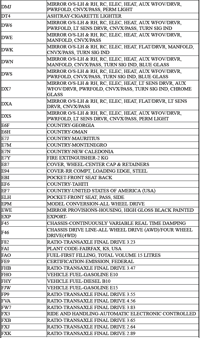
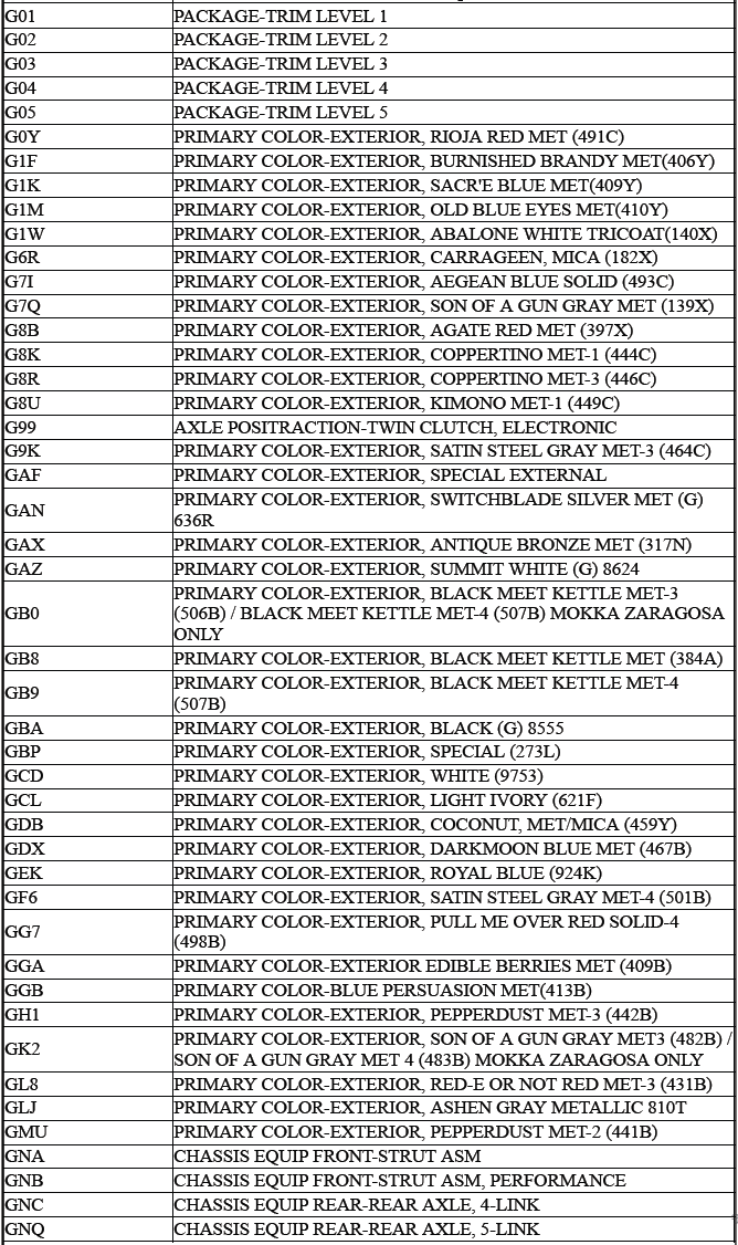
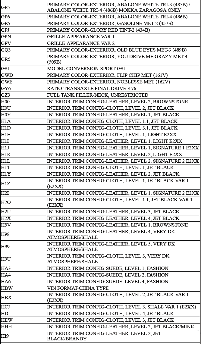
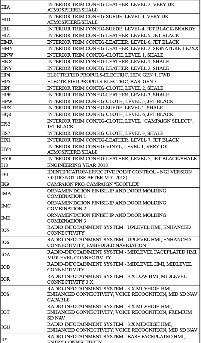
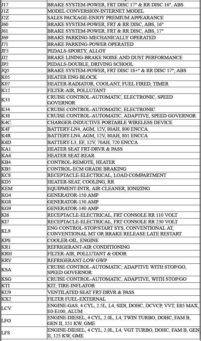
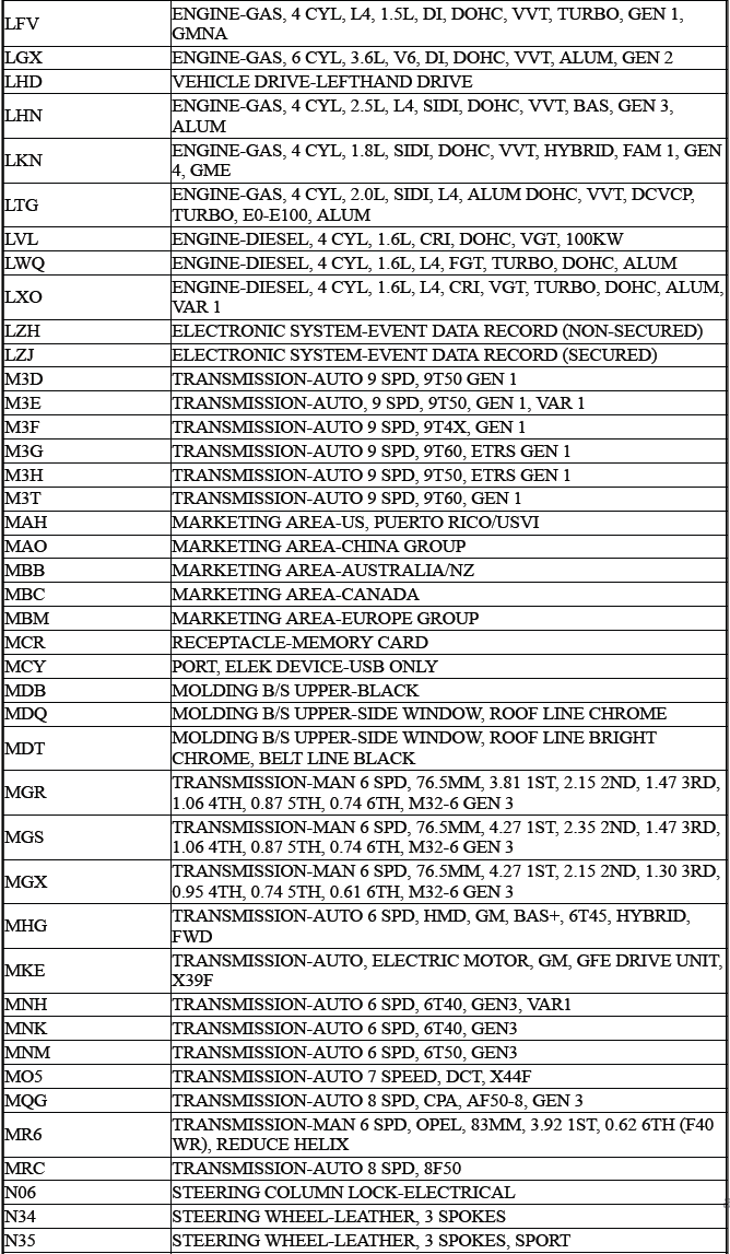
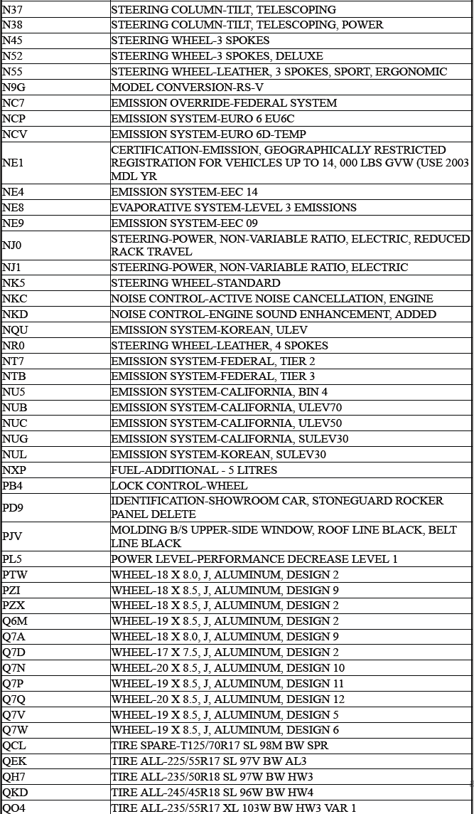
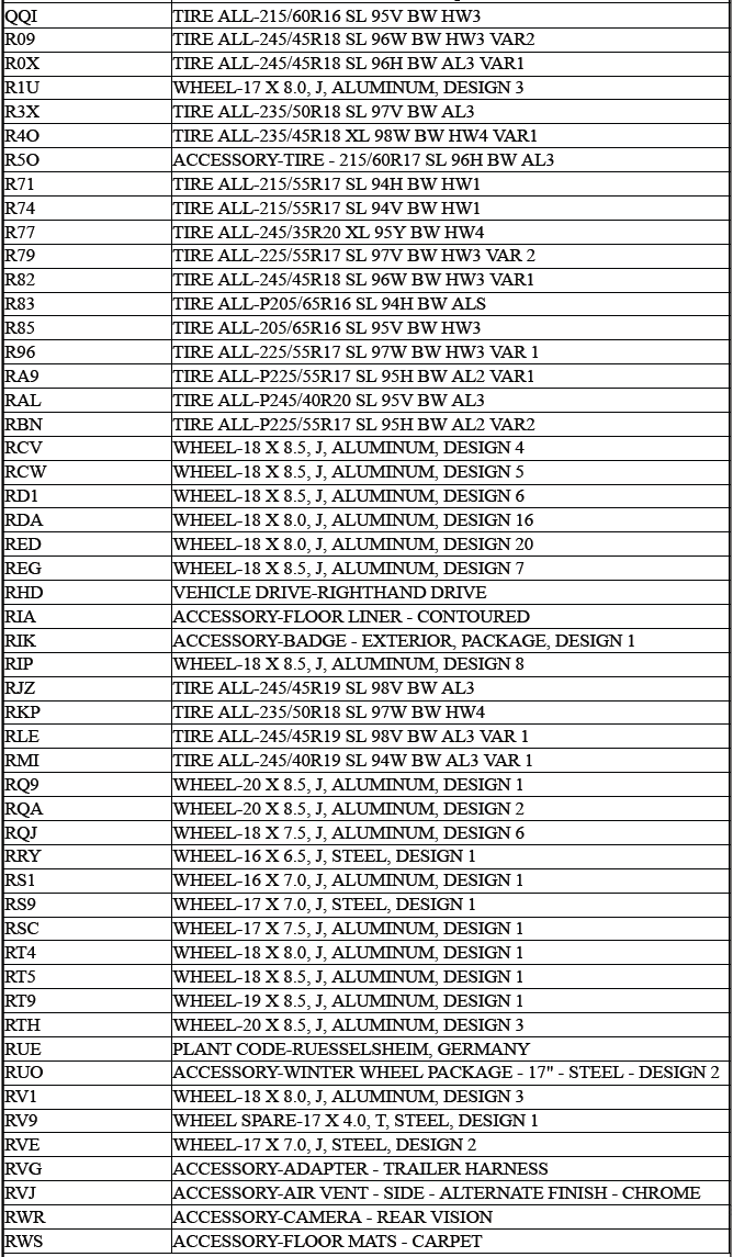
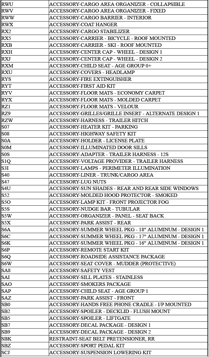
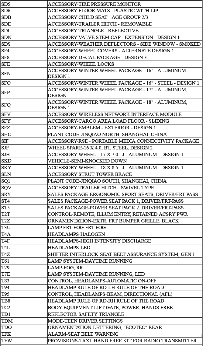
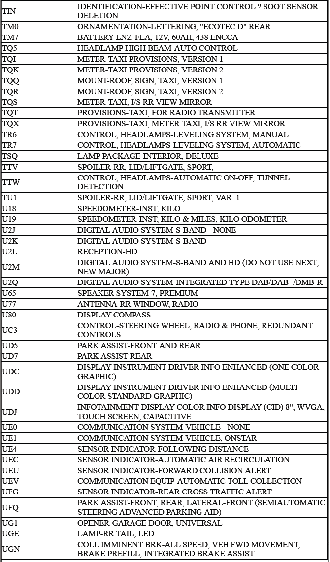
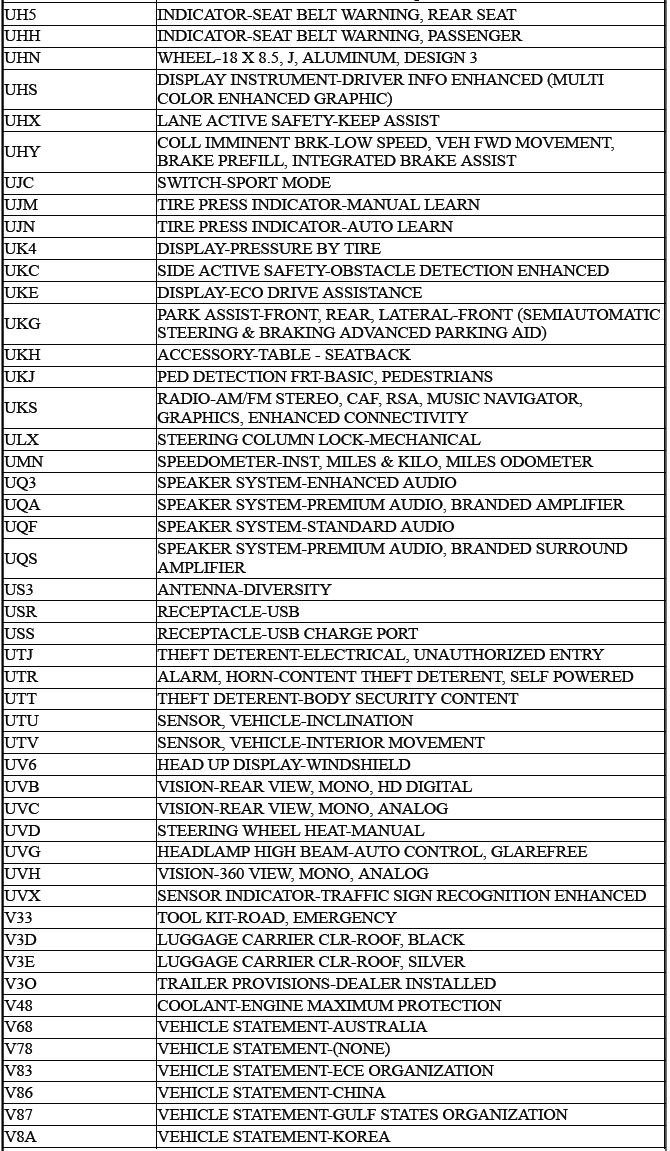
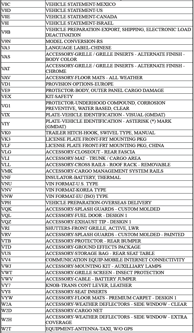
RPO CODE LIST

Fasteners
Metric Fasteners
This vehicle provides fastener dimensions using the metric system. Most metric fasteners are approximate in diameter to equivalent English fasteners. Make replacements using fasteners of the same nominal diameter, thread pitch, and strength.
A number marking identifies the OE metric fasteners except cross-recess head screws. The number also indicates the strength of the fastener material. A Posidrive or Type 1A cross-recess identifies a metric cross-recess screw. For best results, use a Type 1A cross-recess screwdriver, or equivalent, in Posidrive recess head screws.
GM Engineering Standards and North American Industries have adopted a portion of the ISO-defined standard metric fastener sizes. The purpose was to reduce the number of fastener sizes used while retaining the best thread qualities in each thread size. For example, the metric M6.0 X 1 screw, with nearly the same diameter and 25.4 threads per inch replaced the English 1/4 - 20 and 1/4 - 28 screws.
The thread pitch is midway between the English coarse and fine thread pitches.
Fastener Strength Identification
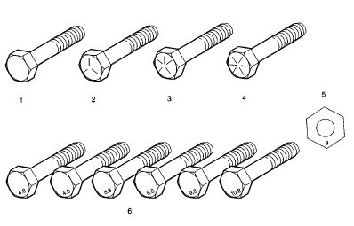
- English Bolt, Grade 2 (Strength Class)
- English Bolt, Grade 5 (Strength Class)
- English Bolt, Grade 7 (Strength Class)
- English Bolt, Grade 8 (Strength Class)
- Metric Nut, Strength Class 9
- Metric Bolts, Strength Class Increases as Numbers Increase
The most commonly used metric fastener strength property classes are 9.8 and 10.9. The class identification is embossed on the head of each bolt. The English, inch strength classes range from grade 2 to grade 8. Radial lines are embossed on the head of each bolt in order to identify the strength class.
The number of lines on the head of the bolt is 2 lines less than the actual grade. For example, a grade 8 bolt will have 6 radial lines on the bolt head. Some metric nuts are marked with a single digit strength identification number on the nut face.
The correct fasteners are available through GM SPO. Many metric fasteners available in the aftermarket parts channels are designed to metric standards of countries other than the United States, and may exhibit the following:
- Lower strength
- No numbered head marking system
- Wrong thread pitch
The metric fasteners on GM products are designed to new, international standards. The following are the common sizes and pitches, except for special applications:
- M6.0 X 1
- M8 X 1.25
- M10 X 1.5
- M12 X 1.75
- M14 X 2.00
- M16 X 2.00
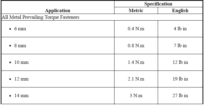
Prevailing Torque Fasteners
Prevailing torque fasteners create a thread interface between the fastener and the fastener counterpart in order to prevent the fastener from loosening.
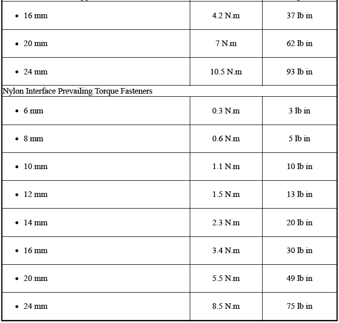
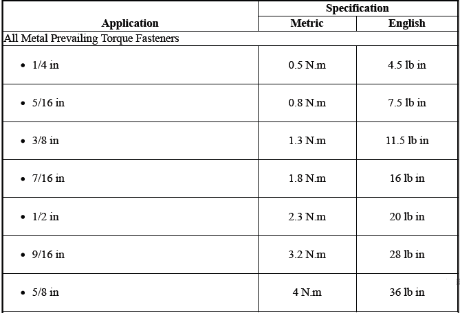
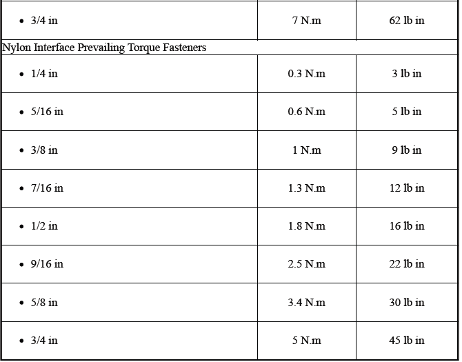
All Metal Prevailing Torque Fasteners
These fasteners accomplish the thread interface by a designed distortion or deformation in the fastener.
Nylon Interface Prevailing Torque Fasteners
These fasteners accomplish the thread interface by the presence of a nylon material on the fastener threads.
Adhesive Coated Fasteners
These fasteners accomplish the thread interface by the presence of a thread-locking compound on the fastener threads. Refer to the appropriate repair procedure in order to determine if the fastener may be reused and the applicable thread-locking compound to apply to the fastener.
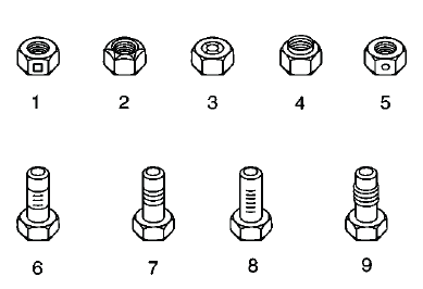
- Prevailing Torque Nut, Center Lock Type
- Prevailing Torque Nut, Top Lock Type
- Prevailing Torque Nut, Nylon Patch Type
- Prevailing Torque Nut, Nylon Washer Insert Type
- Prevailing Torque Nut, Nylon Insert Type
- Prevailing Torque Bolt, Dry Adhesive Coating Type
- Prevailing Torque Bolt, Thread Profile Deformed Type
- Prevailing Torque Bolt, Nylon Strip Type
- Prevailing Torque Bolt, Out-of-Round Thread Area Type
A prevailing torque fastener may be reused ONLY if:
- The fastener and the fastener counterpart are clean and not damaged
- There is no rust on the fastener
- The fastener develops the specified minimum torque against its counterpart prior to the fastener seating
Metric Prevailing Torque Fastener Minimum Torque Development
English Prevailing Torque Fastener Minimum Torque Development
Thread Inserts
General Purpose Thread Repair Kits.
These kits are available commercially.
Repair Procedure
1.
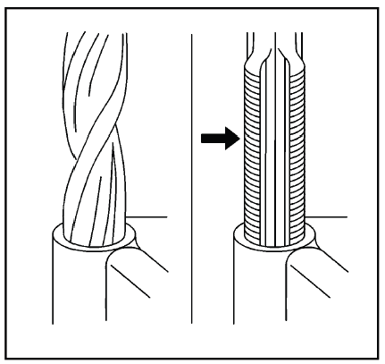
WARNING: Refer to Safety Glasses Warning.
NOTE: Refer to the thread repair kit manufacturer's instructions regarding the size of the drill and tap to use.
Avoid any buildup of chips. Back out the tap every few turns and remove the chips.
Determine the size, the pitch, and the depth of the damaged thread. If necessary, adjust the stop collars on the cutting tool and tap to the required depth.
2. Drill out the damaged threads. Clean out any chips.
3. Lubricate the tap with light engine oil. Tap the hole. Clean the threads.
4.
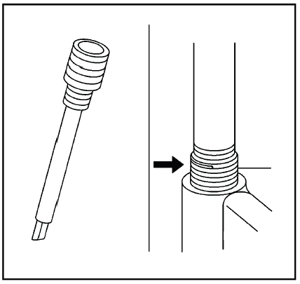
Thread the thread insert onto the mandrel of the installer. Engage the tang of the insert onto the end of the mandrel.
NOTE: The insert should be flush to one turn below the surface.
5. Lubricate the insert with light engine oil, except when installing in aluminum and install the insert.
6. If the tang of the insert does not break off when backing out the installer, break the tang off with a drift.
REGISTERED AND NON-REGISTERED TRADEMARKS
Listed below are Registered Trademarks (Â) or Non-Registered Trademarks () which may appear in this service manual.


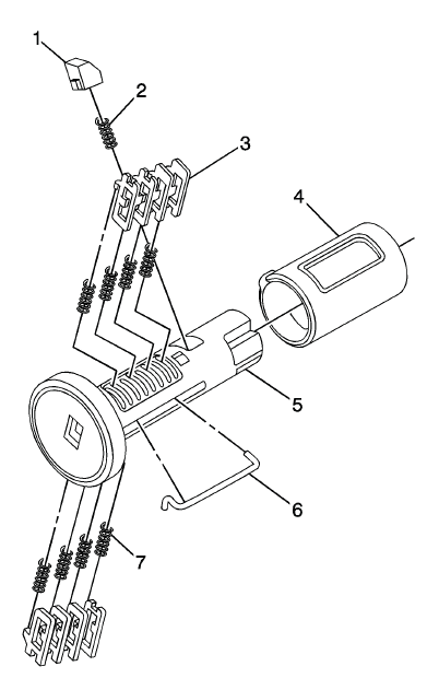
Instrument Panel Compartment Door Lock Cylinder Coding
The internal lock cylinder only uses 4 of the 8 cut positions, 5 - 8. The tumbler positions are on both sides, are not self-retaining, and are not snap in.
1.
NOTE: All lock cylinders for side milled keys have right and left tumblers.
The location of the tooth of the tumbler determines whether it is right of left. Illustrations in this procedure show the right tumblers on the top and the left tumblers on the bottom. All tumblers are marked 1R, 1L, 2R, or 2L. The number being cut depth and the letter meaning right or left.
Hold the instrument panel (I/P) cylinder assembly (4) so the side with the tumbler spring pocket located closest to the head of the cylinder is facing up. This side of the cylinder uses left tumbler.
2. Insert the tumbler spring (6) into each of the 2 spring pockets of the cylinder assembly. This side uses left tumblers.
3. The first tumbler (5) to be loaded (closest to the head of the cylinder) will be the fifth key cut position, which is the fifth number in the key code. Install the tumbler in the slot over the spring.
Install the remaining tumblers following the key code and same process, pressing the tumblers in place until they are secure.
4. Rotate the cylinder assembly. Insert the tumbler spring (6) into each of the spring pockets of the cylinder assembly. This side uses right tumblers.
5. The first tumbler (5) to be loaded will be the sixth key cut position, the sixth number in the key code. Install the first tumbler in the slot over the spring. Install the remaining tumblers following the key code and same process, pressing the tumblers in place until they are secure.
6. Inspect for correct loading of the tumblers by inserting the key into the cylinder. All tumblers should drop flush with the lock cylinder body diameter.
7. Insert the sleeve (3) into the cylinder, the inner sleeve slot must be oriented to the head cylinder side. Rotate the sleeve until the slot match with the tab.
8. Insert the retainer spring (2) into the pocket and the tumbler retainer (1) over the spring. Make sure the tumbler retainer is properly seated and cannot pull out.
9. Lightly lubricate the outside surface in the tumbler area of the lock body and down the key slot using the provided grease. Insert and extract the key 5 times to lubricate the keyway.
10. When the key is removed, the lock should stay together.
11. Insert the key and function the lock 3 times to distribute the grease inside the sleeve.
12. Verify the key position for inserting the lock into the I/P compartment door.
FRONT SIDE DOOR LOCK CYLINDER CODING (FREE WHEELING)
Special Tools
BO-49753 Assembly Tool
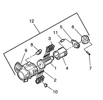
The door lock cylinder uses 8 of the 8 cut positions. The tumbler positions are staggered from side to side, 4 on one side and 4 on the other, are not self-retaining, and are not snap in.
NOTE: All lock cylinders for side milled keys have right and left tumblers.
The location of the tooth of the tumbler determines whether it is right of left. Illustrations in this procedure show the right tumblers on the top and the left tumblers on the bottom. All tumblers are marked 1R, 1L, 2R, or 2L. The number being cut depth and the letter meaning right or left.
1. Hold the door lock cylinder (1) so the side with the 4 tumbler spring pockets faces up, pocket nearest to the cylinder head.
2. Insert the tumbler springs (2) into the 4 spring pockets. This side uses left tumblers.
3. Install the tumbler (3) for key cut position one in the slot nearest to the front of the lock cylinder.
Install the remaining tumblers, key cut positions 3, 5, and 7, following the key code and same process. Press the tumblers in place until they are secure.
4. Check the correct loading of the tumblers by inserting the key into the cylinder. All tumblers should be flush with the lock cylinder body.
5. Turn the cylinder so the side with the 4 tumbler spring wells faces up. This side uses right tumblers.
6. Insert the tumbler springs into the 4 spring pockets.
7. The first tumbler closest to the front of the lock cylinder to be loaded will be the second key cut position, the second number in the key code. Install the remaining tumblers for the key cut positions 4, 6, and 8. Press the tumblers in place until they are secure.
8. Check the correct loading of the tumblers by inserting the key into the cylinder. All tumblers should be flush with the lock cylinder body.
9. Insert the key and lightly lubricate the cylinder body diameter and tumbler surfaces and a small amount in the head of the cylinder using the supplied grease.
10. Insert the sleeve (4) onto the cylinder assembly.
11. Insert the clutch (5) and driver (6) onto the cylinder (1).
12.
Load the cylinder into the BO-49753 assembly tool so that the clutch (1) indexes with the notch in the opening of the tool (2).
13.
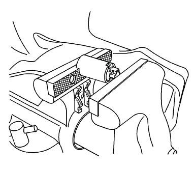
Load the assembly tool with the lock cylinder into a vice and tighten the vice ONLY enough to hold the tool and lock the cylinder in place.
14.
Insert the roll pin (7) into the driver (6) and install it using a 1/16 inch pin punch.
15. Insert the buffer (8) in the case (9), verify the buffer is properly seated.
16. Install the free wheel pin (11) in the sleeve (4) and clutch (5) and insert the assembly into the case (9).
17. With the lock cylinder assembly installed in the case (9), install the retainer (10) and stake the retainer in place using a small punch and hammer to peen the case material onto the exposed ends of the installed retainer (10).
18. Insert the key into the lock and function the lock to check for proper assembly and smooth operation.
FRONT SIDE DOOR LOCK CYLINDER CODING (NON FREE WHEELING)
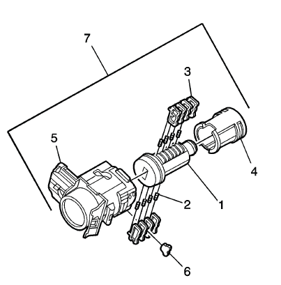
The door lock cylinder uses 8 of the 8 cut positions. The tumbler positions are staggered from side to side, 4 on one side and 4 on the other, are not self-retaining, and are not snap in.
NOTE: All lock cylinders for side milled keys have right and left tumblers.
The location of the tooth of the tumbler determines whether it is right of left. Illustrations in this procedure show the right tumblers on the top and the left tumblers on the bottom. All tumblers are marked 1R, 1L, 2R, or 2L. The number being cut depth and the letter meaning right or left.
1. Hold the door lock cylinder (1) so the side with the 4 tumbler spring pockets faces up, pocket nearest to the cylinder head.
2. Insert the tumbler springs (2) into the 4 spring pockets. This side uses left tumblers.
3. Install the tumbler (3) for key cut position one in the slot nearest to the front of the lock cylinder.
Install the remaining tumblers, key cut positions 3, 5, and 7, following the key code and same process. Press the tumblers in place until they are secure.
4. Check the correct loading of the tumblers by inserting the key into the cylinder. All tumblers should be flush with the lock cylinder body.
5. Turn the cylinder so the side with the 4 tumbler spring wells faces up. This side uses right tumblers.
6. Insert the tumbler springs into the 4 spring pockets.
7. The first tumbler closest to the front of the lock cylinder to be loaded will be the second key cut position, the second number in the key code. Install the remaining tumblers for the key cut positions 4, 6, and 8. Press the tumblers in place until they are secure.
8. Check the correct loading of the tumblers by inserting the key into the cylinder. All tumblers should be flush with the lock cylinder body.
9. Insert the key and lightly lubricate the cylinder body diameter and tumbler surfaces and a small amount in the head of the cylinder using the supplied grease.
10. Insert the sleeve (4) onto the cylinder assembly.
11. Insert the assembly into the case (5).
12. With the lock cylinder assembly installed in the case (5), install the retainer (6) and stake the retainer in place using a small punch and hammer to peen the case material onto the exposed ends of the installed retainer (6).
13. Insert the key into the lock and function the lock to check for proper assembly and smooth operation.
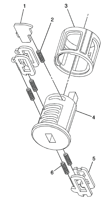
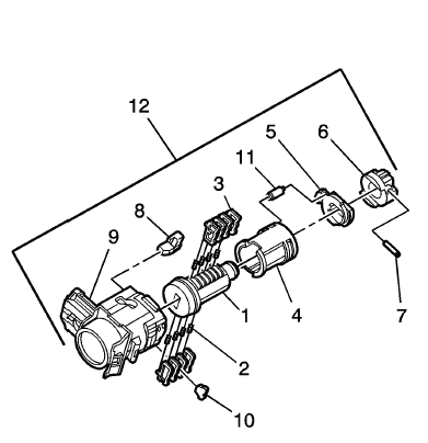
Lock Cylinder Coding - Ignition
The ignition lock cylinder uses 8 key cut positions, 1 - 8. The ignition cylinder tumblers (3) are located on alternate sides of the cylinder (5). They are not snap-in and are not self-retaining. It follows the key code with the first tumbler being the first depth of the key code, closest to the head of the key.
NOTE: All lock cylinders for side milled keys have right and left tumblers.
The location of the tooth of the tumbler determines whether it is right of left. Illustrations in this procedure show the right tumblers on the top and the left tumblers on the bottom. All tumblers are marked 1R, 1L, 2R, or 2L. The number being cut depth and the letter meaning right or left.
1. Hold the ignition cylinder assembly (5) so the side with the tumbler spring pocket located closest to the head of the cylinder is facing up.
2. Insert the tumbler spring (7) into each of the 4 spring pockets of the cylinder assembly. This side of the cylinder used left tumblers.
3. The first tumbler (3) to be loaded will be the first key cut position, which is the first number in the key code. Install the tumbler in the slot over the spring. Install the remaining tumblers following the key code and same process, pressing the tumblers in place until they are secure.
4. Rotate the cylinder assembly. Insert the tumbler spring into each of the spring pockets of the cylinder assembly. This side of the cylinder used right tumblers.
5. The first tumbler (3) to be loaded will be the second key cut position, the second number in the key code. Install the first tumbler in the slot over the spring. Install the remaining tumblers following the key code and same process, pressing the tumblers in place until they are secure.
6. Inspect for correct loading of the tumblers by inserting the key into the cylinder. All tumblers should drop flush with the lock cylinder body diameter.
7. With the key in the cylinder assembly insert the round connector (6), insert the retainer spring (2) in the retainer slot located in the cylinder assembly. Insert the retainer (1) lining it up in the slot over the spring. Depress the retainer and hold.
8. Insert the cylinder into the sleeve (4) as shown in the print. Make sure the actuator stays located properly in the cylinder.
9. When the key is removed, the lock should stay together.
10. Lightly lubricate the outside surface in the tumbler area of in the lock body and down the key slot using the provided grease. Insert and extract the key 5 times to lubricate the keyway.
11. Insert the key and function the lock 3 times to distribute the grease inside the sleeve.
12. Verify the key position for inserting the lock into the column.
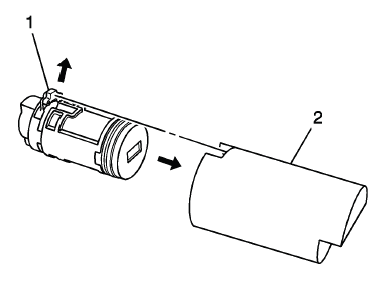
REAR COMPARTMENT LID LOCK CYLINDER CODING
The door lock cylinder uses 8 of the 8 cut positions, 1 - 8. The tumbler positions are staggered from side to side, 4 on one side and 4 on the other, are not self-retaining, and are not snap in.
1.
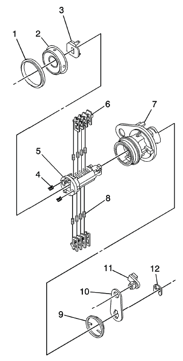
NOTE: All lock cylinders for side milled keys have right and left tumblers.
The location of the tooth of the tumbler determines whether it is right of left. Illustrations in this procedure show the right tumblers on the top and the left tumblers on the bottom. All tumblers are marked 1R, 1L, 2R, or 2L. The number being cut depth and the letter meaning right or left.
Hold the cylinder (5) so the side with the 4 tumbler spring pockets nearest the cylinder head faces up. This side uses left tumblers.
2. Insert the tumbler springs (8) into the 4 spring pockets.
3. Install the tumbler (6) for key cut position one in the slot nearest to the front of the lock cylinder.
Install the remaining tumblers, key cut positions 3, 5, and 7, following the key code and same process. Press the tumblers in place until they are secure.
4. Check the correct loading of the tumblers by inserting the key into the cylinder. All tumblers should be flush with the lock cylinder body.
5. Turn the cylinder so the opposite side spring pockets faces up. This side uses the right tumbler.
6. Insert the tumbler springs into the 4 spring pockets.
7. The first tumbler closest to the front of the lock cylinder to be loaded will be the second key cut position, the second number in the key code. Install the remaining tumblers for the key cut positions 4, 6, and 8. Press the tumblers in place until they are secure.
8. Check the correct loading of the tumblers by inserting the key into the cylinder. All tumblers should be flush with the lock cylinder body.
9. Insert the key and lightly lubricate the cylinder body diameter and tumbler surfaces and a small amount in the head of the cylinder using the supplied grease.
10. Install 2 springs (4) into the 2 spring pockets in the head of the lock cylinder.
11. Holding the tumblers snap the shutter assembly (3) onto the cylinder.
12. Insert the cylinder into the case assembly (7) and install the cap (2) and the gasket double (1) around the cap.
13. Add the torsion spring (9).
14. Insert the rod clip (11) in the lever (10) and place it in the cylinder assembly.
15. Insert the E-clip (12) to securely hold the lever to the cylinder.
16. Insert the key into the lock and rotate it to check for proper assembly and smooth operation.
LIFTING AND JACKING THE VEHICLE
NOTE: The use of a LOW PROFILE LIFT ARMS SYSTEM may be required to avoid unwanted contact with the vehicle's body and structure depending on lifting equipment used. Refer to the manufacture's recommendation for their applications of low profile lift arms system for their lifting equipment.
WARNING: To avoid any vehicle damage, serious personal injury or death:
- When major components are removed from the vehicle and the vehicle is supported by a hoist, support the vehicle with jack stands at the opposite end from which the components are being removed and strap the vehicle to the hoist.
- When performing work in the engine compartment or under the vehicle, ensure that the hood is fully open, or opened to its secondary latch. When the hood is opened to the secondary latch, the vehicle will disable the remote start features from the key fob and OnStar mobile app. Failure to open the hood, or open the hood to the secondary latch while doing a repair in the engine compartment or under the vehicle can result in inadvertent vehicle starting which could result in personal injury or damage to a vehicle.
WARNING: To avoid any vehicle damage, serious personal injury or death, always use the jackstands to support the vehicle when lifting the vehicle with a jack.
CAUTION: Perform the following steps before beginning any vehicle lifting or jacking procedure:
- Remove or secure all of the vehicle contents in order to avoid any shifting or any movement that may occur during the vehicle lifting or jacking procedure.
- The lifting equipment or the jacking equipment weight rating must meet or exceed the weight of the vehicle and any vehicle contents.
- The lifting equipment or the jacking equipment must meet the operational standards of the lifting equipment or jacking equipment manufacturer.
- Perform the vehicle lifting or jacking procedure on a clean, hard, dry, level surface.
- Perform the vehicle lifting or jacking procedure only at the identified lift points. DO NOT allow the lifting equipment or jacking equipment to contact any other vehicle components.
Failure to perform the previous steps could result in damage to the lifting equipment or the jacking equipment, the vehicle, and/or the vehicle contents.
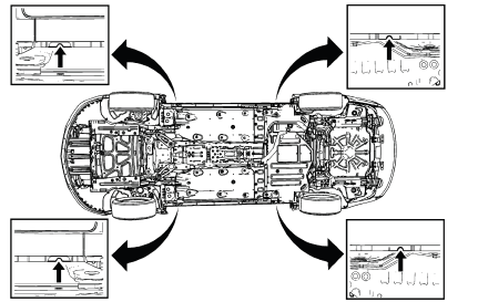
Vehicle Lifting - Frame Contact Lift
Front Lift Pads
When lifting the vehicle with a frame-contact lift, place the front lift pads on the rocker outer panel weld flange, as shown
Rear Lift Pads
When lifting the vehicle with a frame-contact lift, place the rear lift pads on the rocker outer panel weld flange, as shown.
Vehicle Jacking
CAUTION: When you are jacking the vehicle at the front locations, be certain that the jack or the jack lift pad does not contact the front fascia, front fascia air dam, or the front fenders. If such contact occurs, vehicle damage may result. When jacking at selected front locations additional clearance may be required for the jacking points.
NOTE: When you are lifting a vehicle with a service jack, block the wheels at the opposite end from which you are lifting. Use jack stands to provide additional support.
Front of Vehicle
When using a service jack under the front of the vehicle use one of the following locations: Place the service jack pad in the same location as shown for the front lift pads.
Rear of Vehicle
NOTE: Place jackstands ONLY under strong and stable vehicle structures.
Place the service jack pad in the same location as shown for the rear lift pads.
READ NEXT:
 Repair Instructions
VOLATILE MEMORY PROGRAMMING
Electric Window Lifters
Move all the windows to the topmost position and hold the switch pressed down
for 2 seconds.
Sliding Sunroof
Move the sliding roof to the respectiv
Definition of Danger, Warning, Caution, and Note
The diagnosis and repair procedures in a GM Service Manual contain both
general and specific Dangers,
Warnings, Cautions, Notes or Importants. GM is dedicated to the presentation of
service informat
SEE MORE:
Ride Control Systems
Traction Control/Electronic
Stability Control
System Operation
The vehicle has a Traction Control
System (TCS) and StabiliTrak, an
electronic stability control system.
These systems help limit wheel slip
and assist the driver in maintaining
control, especially on slippery road
conditions.
TCS acti
Repair Instructions
Forward Range Radar Module Inspection
Inspection Procedure
1.
CONTROL MODULE DTC CHECK - Using a scan tool, perform the Vehicle DTC
Information function - Verify there are no current control module DTCs set. If
any DTC is set, refer to Diagnostic Trouble Code (DTC) List - Vehicle.
2. Check the al
