Opel Insignia: Specifications, Schematic Wiring Diagrams
Specifications
FASTENER SPECIFICATIONS (OFF VEHICLE)
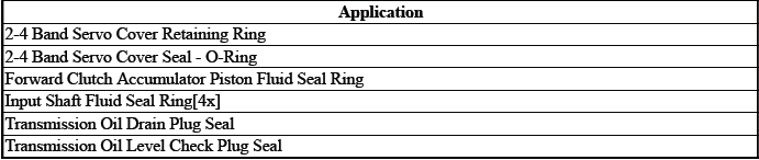
Single Use Non-Threaded Fasteners/Components
NOTE: All fasteners/components listed in this table MUST BE DISCARDED and replaced with NEW after removal.
Reusable Threaded Fastener Tightening Specifications
NOTE: All fasteners listed in this table can be reused after removal.
.png)
FASTENER SPECIFICATIONS (ON VEHICLE)
Single Use Non-Threaded Fasteners/Components
NOTE: All fasteners/components listed in this table MUST BE DISCARDED and replaced with NEW after removal.

Single Use Threaded Fastener/Component Tightening Specifications
NOTE: All fasteners/components listed in this table MUST BE DISCARDED and replaced with NEW after removal.
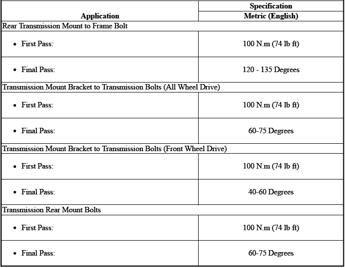
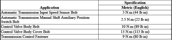
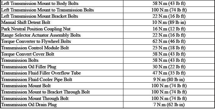
Reusable Threaded Fastener Tightening Specifications
NOTE: All fasteners listed in this table can be reused after removal.
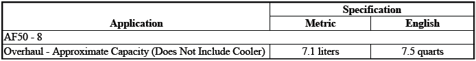
APPROXIMATE FLUID CAPACITIES
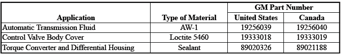
ADHESIVES, FLUIDS, LUBRICANTS, AND SEALERS
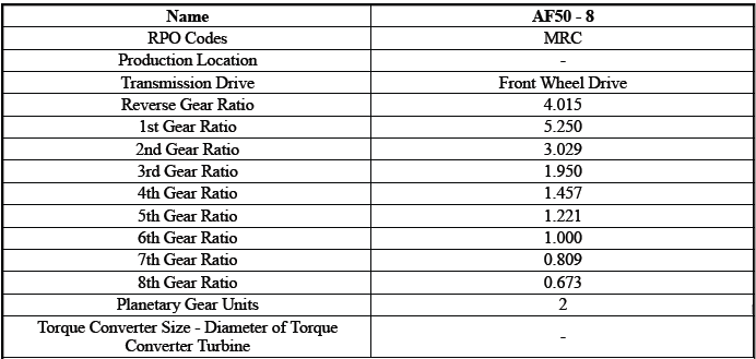
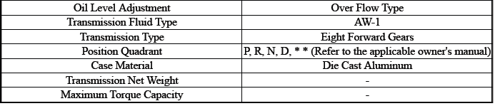
TRANSMISSION GENERAL SPECIFICATIONS
RANGE: REFERENCE
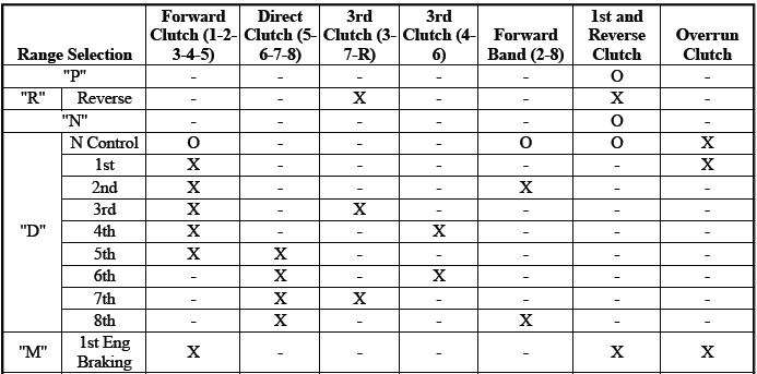
Full output, fully engaged = "X".
Zero output, fully disengaged = " - "
Output control engaged = "O"
SHIFT SOLENOID VALVE STATE AND GEAR RATIO
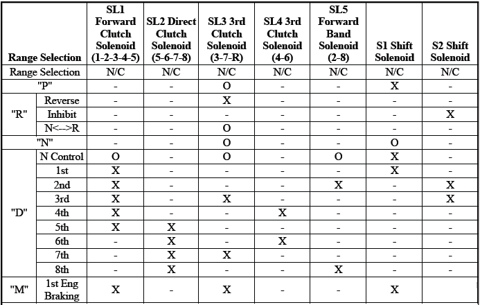
Full output, fully engaged = "X".
Zero output, fully disengaged = " - "
Output control engaged = "O"
N/C = "Normal Close"
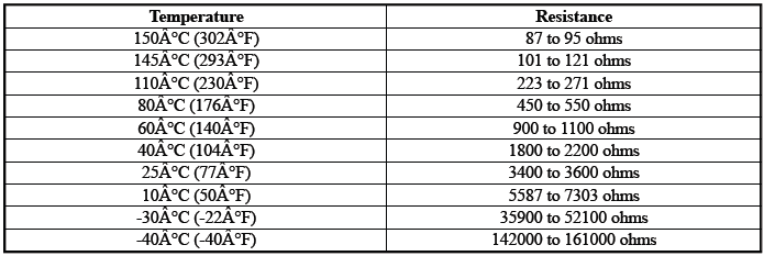
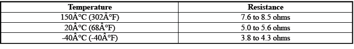
TEMPERATURE VERSUS RESISTANCE (B13 TRANSMISSION FLUID TEMPERATURE SENSOR)
TEMPERATURE VERSUS RESISTANCE (Q27 PRESSURE CONTROL SOLENOID VALVE)
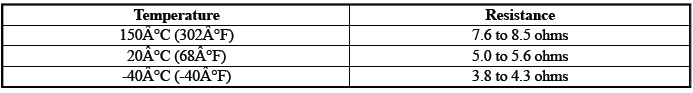
TEMPERATURE VERSUS RESISTANCE (Q32 SHIFT SOLENOID VALVE 1)
Schematic Wiring Diagrams
AUTOMATIC TRANSMISSION CONTROLS WIRING SCHEMATICS
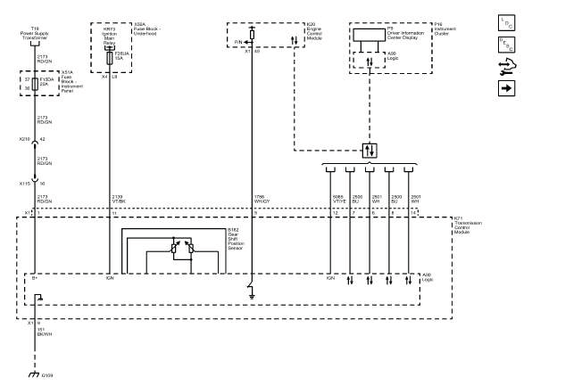
Power, Ground, Serial Data, and MIL
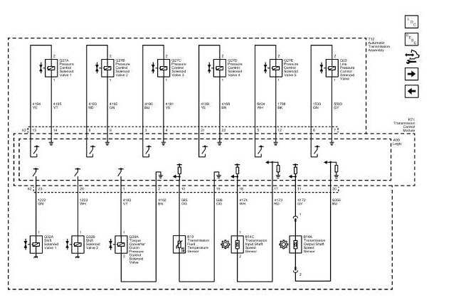
Speed and Temperature Sensors, Pressure and Shift Controls (Start/Stop)
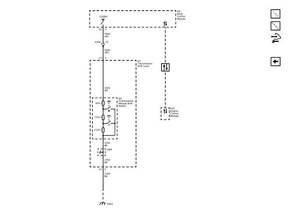
Tap Up/Tap Down Switches
READ NEXT:
 Component Locator
DISASSEMBLED VIEWS
Case and Associated Parts (1 of 2)
Transmission Control Module Bolt [3x]
Transmission Control Module
Manual Shift Shaft Seal
Transmission Fluid Filler Tube Plug
Transmission
Diagnostic Information and Procedures
DTC P0218
Diagnostic Instructions
Perform the Diagnostic System Check prior to using this diagnostic
procedure: Refer to Diagnostic System
Check - Vehicle
Review the description of Strategy Base
Repair Instructions - On Vehicle
Gear Selector -N- Position Learn
Diagnostic Instructions
Perform the Diagnostic System Check prior to using this diagnostic
procedure: Refer to Diagnostic System
Check - Vehicle
Review the descr
SEE MORE:
Vehicle Personalization
The following are all possible
vehicle personalization features.
Depending on the vehicle, some
may not be available.
For System, Apps, and Personal
features and functions, see
"Settings" in the infotainment
manual.
To access the vehicle
personalization menu:
1. Touch the Settings icon on the
Hom
Component Locator
DISASSEMBLED VIEWS
Case and Associated Parts (1 of 2)
Transmission Control Module Bolt [3x]
Transmission Control Module
Manual Shift Shaft Seal
Transmission Fluid Filler Tube Plug
Transmission Fluid Filler Tube Shipping Plug Seal
Front Wheel Drive Shaft Oil Seal- Right Side
Automatic Transm
